Search principle
To find a fault in any vehicle on-board network system, you should use the method of sequential elimination of elements. The point is to consistently check electrical appliances and sections of the circuit, excluding elements from the list of reasons that could cause a breakdown. To do this, you need to clearly understand the design and operating principle of the system. When troubleshooting, you need to move from the components that require the least effort to check, to the most difficult to diagnose elements.
Electrical diagram
We immediately emphasize that the pinout of connectors and color markings of wires may differ not only between different models of the same automaker, but also among one model of different years of manufacture. Before you start searching for the cause of the breakdown, you need to find an electrical diagram specifically for your car model.
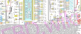
We will consider the principle of operation of brake lights and the troubleshooting algorithm using the example of the VAZ 2101-2102 circuit. The photo shows the general diagram of the vehicle's lighting and light signaling. We need to isolate the components involved in the operation of brake lights.
- 6 – mounting fuse block;
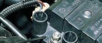
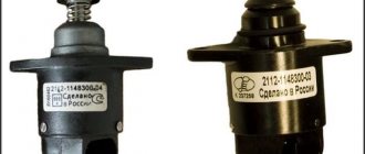
- 13 – brake light switch. It is a non-locking button (returns to its original position after removing the force). Located directly next to the brake pedal. When the brake pedal is released, the contacts of the limit switch are open, no current passes through it. Accordingly, when pressed, the contacts close, allowing flow through the lamps;
- 19 – lamps that light up when you press the brake pedal.
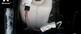
We do not have a diagram of the mounting block, but we know in advance that the brake lights only work when the ignition is on. There is a wire from the mounting block to the brake light limit switch, on which there is a constant + after the ignition is turned on. As soon as the limit switch contacts close, + goes to the brake light bulbs, which are connected in parallel. The “ground” of the rear lights is common and consists of a wire screwed to the car body.
In the diagram we presented, the elements are depicted as close as possible to how they look in reality. Don’t be alarmed if you only find a schematic diagram for your car with symbolic images of the elements. Schematic diagram of external lighting for VAZ 2114, 2115:
- 3 – mounting block;
- 8 – lamps for side lights and brake lights;
- 11 – brake light limit switch;
- K4 – relay for monitoring the serviceability of brake light lamps and side lights.
Fuses responsible for monitoring the lamps of a VAZ car
Despite the presence of special relays in the mounting block, the driver must also pay attention to the markings of the fuses that are responsible for controlling the lighting devices. In some cases, precisely because they burn out, the relay begins to signal lamp failure.
F 1 -10 amperes – is responsible for the rear fog lights and the indicator for their activation;
F 8 -7.5 amperes – it is responsible for the operation of the right fog lamp;
F 9 -7.5 amperes – it is responsible for the operation of the left fog lamp;
F 12 -7.5 amperes – this fuse is responsible for the operation of the low beam of the right headlight of the car;
F 13 -7.5 ampere – this fuse is responsible for the operation of the low beam of the left headlight of the car;
F 14 -7.5 amperes – this fuse is responsible for the operation of the high beam lighting of the left headlight of the car, as well as for the indicator that it is turned on;
F 15 -7.5 ampere - this fuse is responsible for the operation of the high beam lighting of the right headlight of the car, as well as for the indicator that it is turned on.
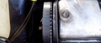
These fuses are clearly marked, which can also be seen in photo No. 3, and are responsible for the serviceability of not only the device itself, but also the electrical circuit. Therefore, if any problems are detected in the lamps, first of all you need to pay attention to the fuses.
As stated above, in some modifications, and depending on the years of manufacture of the car, the location and some markings may be changed. But when buying a car, the kit includes technical documentation, where everything is described, but in case it is missing, then you can use the photos that are available in this publication.
Their installation is easy. The fact is that in the block where they are located there is a special key, with which you can easily remove all the fuses, and put them in place by lightly pressing on them.
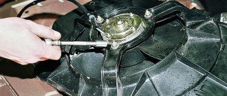
Photo 4
In order to remove and replace the control relay, you also do not need to make much effort. They have a fork at their base, and if you grab it with your hand and pull it up with a little effort, it can be easily removed. It can be put in place in the same way.
It is important to know that in the case of tuning a car, namely adding LEDs to the headlights, a situation may arise that all the fuses to which they are connected begin to blow out. In this case, experts recommend replacing them with resistors. You need to ask the specialist from whom the diodes themselves are purchased about which resistor is best. Installing the resistor itself will not be difficult, since its installation follows the principle of installing and removing a fuse.
Fault localization
Understanding the operating principle allows you to determine exactly why the brake lights may not light up:
The fuse has blown. In the diagram, the fuses are marked with the letter F (from English - Fuse) and the serial number of the seat in the fuse block, for example, F3;- poor contact at connectors;
- the light bulbs have burned out, but since the lights are connected in parallel, the likelihood that 2 lamps will burn out at once is extremely low;
- poor contact on the negative terminal of the lights. In this case, problems may begin not only with the feet, but also with the lighting of the remaining lamps in the lanterns;
- Damage to the negative track in the lamp board. From the total mass directly to the brake light lamp, the minus goes along a special path on the board. The path may collapse from water or mechanical impact;
- malfunction of the brake light switch, the so-called frog;
- broken wiring, oxidation of contacts.
How to unscrew the caliper nipple?
When swaying the brakes, usually all people have the same algorithm of action. First, a hose is put on the caliper nipple, then the nipple itself is released with an open-end wrench. But what to do if the nipple doesn’t want to budge? It is better to use a socket wrench for these purposes and here's why:
If your brake caliper nipple is soured and you try to unscrew it with a regular spanner/open-end wrench, you are making a mistake. The surface area of these wrenches is small, but the risk of tearing off the edges on the nipple is unusually high.
It is much safer to use a socket wrench instead. With a long handle. We treat the stubborn guy with penetrating lubricant, let the oxides loosen their grip, and carefully loosen the nipple. The brakes are ready to be bled.
This is another sound piece of advice to add to your knowledge base. Since the nipples on the calipers, as we all know, are made of soft material and even the slightest turn of the spanner can tear off the splines, forcing you to resort to using pliers. Any use of materials is allowed only if there is a hyperlink to 1GAI.ru
How to troubleshoot?
The most common reasons that the brake light on the VAZ 2114 does not work are the following factors:
- Fuse failure.
- Broken wires in one of the sections of the circuit.
- Limit switch faulty.
- Bulbs burn out.
- Oxidation of contacts in lamp sockets.
- Damage to the contact board.
The most common and at the same time the most easily removable of the above reasons is a blown fuse. To identify such a malfunction, you need to examine the fuse box. A 10-amp fuse F3 is responsible for the brake lights, which also protects the ignition switch, computer and interior lighting.
Malfunctions in the operation of the latter may also indicate a malfunction of the stop fuse (and in this case, troubleshooting should begin with the block). If it turns out that the fuse has blown, then you should replace it with a new, similar one.
A new fuse installed in place of a failed one must be designed for exactly the same maximum current. If it is less, the fuses will blow more often, and if it is more, the protected device itself may burn out.
The problem may also be in the fuse block itself - sometimes the tracks on its printed circuit boards burn out or the contact legs oxidize. In order to check its serviceability, it is enough to measure the voltage at the contacts of the newly installed fuse.
Where is the heater relay on a VAZ 2114?
Dear visitors of the site “Everything about cars”! We will be very grateful for your comments on the video clip “Where is the heater relay on a VAZ 2114?” registration is not required for this. We also ask you to let us know if you have any problems playing the video.
Thx Explained everything very clearly, it made my work very easy
11/21/2017 – 12:57 Vyacheslav Kuznetsov
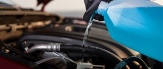
unnecessary steps in disassembling the panel. and one more important factor: it is better to drain the remaining antifreeze from the pipes and the radiator of the stove by disconnecting the pipe from the street that goes to the tap, so that nothing gets into the cabin
20.11.2017 – 08:32 derik Ishtar
10.28.2017 – 22:47 Pavel Parsuk
It's not that simple. I'm a fucker. I have to change all this And I also have the entire interior in antifreeze.. ENTIRE Now disassemble it all again and dry it all. At 2114, replacing the stove - HELL
09/30/2017 – 00:34 Ivan Ivanovich
I changed it in between when I was making noise. By the way, there is such a trick: if you drill out a spot weld in a metal brace to the left of the steering wheel, the panel can be removed without touching the steering wheel. and in general, the stove can be changed by unscrewing the fastening bolts so as to raise the panel a little, and the ecu can not be touched at all.
I'm already crazy. I used to have a VAZ 2107, the radiator was leaking there too, I thought there was a problem, I took such Kama Sutra shit like hell, so here in general the floor of the car needs to be dismantled, and as luck would have it, when it got cold, I turned it on for the first time on a newly purchased car the stove and on you, all the antifreeze is in the cabin.
09/08/2017 – 14:11 alexholus
Well, it’s not true, it’s not hell, it only took me a day and a half to replace the faucet, the main thing is to do it slowly and carefully
08/26/2017 – 01:06 SERGEY BORCHOV 07/29/2017 – 11:04 SERGEY BORCHOV
The boys here need only 6 self-tapping screws and 2 clamps. Using 1 Phillips screwdriver, unscrew the self-tapping screw in the upper right side of the panel 2 at the bottom under the board. Pull the ponnel towards you more boldly and place it towards the top on the bottom plate where the bottom screw is screwed in. 3 loosen 2 clamps on the radiator and remove the pipes. 4 Unscrew the self-tapping screw securing the cable so that it does not interfere with pulling out the stove. 5, unscrew the three self-tapping screws securing the radiator. In two, the assistant wakes up the hand, pulls the panel towards himself and drags the radiator from the block to the top of the other. 2113 14 15 their panel is flexible for me business hour.
07/09/2017 – 19:42 Dima Makalatia
Thank you very much, the torpedo is unscrewed, drain the antifreeze tomorrow morning.
06/19/2017 – 05:23 Evgen Zhurbenko
06/02/2017 – 00:43 Alexey Kanavsky
The question is, why blow out the hose to remove the air plug, if when you turn on the engine, I think so, maybe I’m mistaken, the pump itself will pump out excess air from the stove and through the expansion tank, where the valve cover itself releases excess air?
05/10/2017 – 06:07 Andrey Ivanov
I wonder who the hell is interested in what pieces of iron you have been in love with since your childhood?
05/08/2017 – 23:48 Andrey Egorov
05/05/2017 – 07:41 Pavel Kornev
What's the second song playing?
04/25/2017 – 00:59 smfrteks
I'll cut it off. this fucking shelf. And the developers would cram it into a pot. It's crazy how much he blew up. I understand less. It’s true that you have to pull the torpedo as hard as you can. It’s really scary to rip something out.
04/01/2017 – 03:59 Taz Taz
It's long and tedious, I did it much easier and faster, without assistants and disassembling half the car.
03/16/2017 – 16:13 PinKod 1993
6 hours of work, and the job is done, if there was a desire, and there was no need to cut anything
Malfunction of the lights themselves
If during the check from the fuse box to the limit switch no problems are found, then you should move on. Now you should test the wiring from the second limit switch connector to the stop connectors with a tester. If it is working, then you need to check the board. The printed circuit board on which the taillights are mounted is not ideal, and is one of the biggest problems of all VAZ cars.
Its tracks often burn out or peel off, causing the lights to stop working. This problem can be solved in two ways - either re-solder the tracks (which can be done with a regular soldering iron, although not in road conditions) or replace the board with a new one (most motorists choose the second option).
Another reason why the VAZ 2114 brake lights do not work may be oxidation of the lamp sockets. In order to eliminate this problem, it is enough to clean all contacts from oxides that have appeared on them.
This is best done in one of the following ways:
- small grit sandpaper;
- WD-40 solution;
- kerosene;
- purified gasoline (“galosh”).
You should absolutely not use gasoline or other solvents to clean contacts.
The last option for faulty stops is the light bulbs themselves. It makes no sense to give any detailed advice here - you just need to replace the burnt out light bulbs with new ones.
By following all the tips listed above, the car enthusiast gets the opportunity to check the entire electrical circuit of the brake lights, starting from the fuse box and ending with the bulbs in the lamps. Thanks to this, the guarantee that the fault will be accurately detected and eliminated is 100%.
Explanation of the additional fuse and relay block
To turn on the main systems of any car, the manufacturer has designed the installation of auxiliary fuses. As a rule, they are located in the center console area. Each auxiliary module consists of several important relays and fuses.
In this particular case, the box is located to the left of the glove compartment, behind the side trim of the center console. To quickly access the box, you need to remove part of the plastic protection. The protection is attached to Phillips bolts, so you need to prepare the appropriate screwdriver.
Location of additional fuse and relay box 2114, 2115, 2113
Additional unit in the cabin Diagram of the additional unit
Table 3. Explanation of the additional fuse and relay block
| № | Current, A | Purpose (Fuses) |
| 1 | 15 | Main distribution relay |
| 2 | 15 | Controller power |
| 3 | 15 | Fuel pump |
| № | Purpose (Relay) | |
| K4 | Fuel pump | |
| K5 | Cooling fan | |
| K6 | Main system control relay |
There are also options for other decryptions.
Explanation of the additional fuse and relay block
Relay:
Fuse:
f2 - main relay;
f3 - ECU (electronic control unit).
Relays that control the supply of current are present in the design of many vehicles. They are designed to perform a very important function - they turn on and off important electrical devices and mechanical systems of the vehicle. In simple terms, this is a device for supplying current to a required element.
Additional Tips
Before each trip, especially over long distances, you should check the functionality of all lighting equipment, including brake lights. In order to reduce the likelihood of breakdowns along the way, you need to periodically check the condition of the sockets and bases of the rear light bulbs, and periodically clean them of oxides and dirt.
In case a breakdown does occur, you should always have an additional set of light bulbs and 10 amp fuses in your car, as well as a multimeter to check them.
Starter, ignition, rear fog lamp relay
In order to carry out quick checks and repairs, the ignition system relay is installed under the front dashboard of the car, behind the hood release handle. It is located just below the central dashboard. The module is closed with a plastic plug, which must be opened slightly to test for functionality.
Starter, ignition, rear fog lamp relay
Next to the indicated relay, there is a similar one for the rear fog lights and the starter.
The main task of the relay when igniting is to reduce the applied load to the contacts. When the engine starts, the relay turns off some electrical circuits in the vehicle system. The system is used not only in injection, but also in carburetor engines.
In the event of a malfunction or malfunction in the ignition system, it is necessary to monitor the operation of the relay. For this purpose, open the box and carefully remove the desired element. It is attached using contacts to special grooves. The first thing to do is look at the oxidation of the contacts, if necessary, clean them with a soft cloth or treat them with a special liquid.
To check functionality, you need to use a regular multimeter. We connect to incoming connections and check the numbers. If there is no short circuit when current is applied, it means the element is not working. Replacement is carried out in a similar manner. It is necessary to use a standard element with the number of amperes indicated on the housing.
How to check wiring
You can diagnose electrical equipment using a voltmeter, ohmmeter or multimeter, or special diagnostic stands. Computer diagnostics are also carried out, during which error codes and main indicators of the machine’s on-board network are read. To independently check circuits and troubleshoot electrical faults, one multimeter or signal lamp is enough.
We use a multimeter
Fuses in the on-board network are considered the “weakest” link in terms of durability. In case of emergency situations (for example, in the event of a short circuit), the safety elements “take the blow”, protecting the rest of the electrics and electrical equipment of the machine. Fuses cannot be restored and must be replaced during repairs.
Checking the voltage
Before checking the wiring in the car, it is necessary to measure the voltage of the electrical circuit between individual components and electrical equipment. You can call like this:
- Set the multimeter to voltmeter mode.
- Connect one probe of the measuring device to the “minus” of the battery or to the ground of the machine.
- Connect the second probe to the supply wire of the circuit.
If a certain value appears on the device display, then there is voltage in this section of the electrical circuit. You can compare the values with those required according to the vehicle's owner's manual.
Looking for a short circuit
After measuring the voltage, search for short circuits. This will require either a multimeter or a pilot light. As for the lamp, if the wiring is in good condition and there is no short circuit, it should not light up.
A short circuit in the wiring, as well as a lack of voltage (zero or infinite resistance in the electrical circuit), indicates a malfunction in one of 2 components:
- Consumer - electrical equipment, devices, fuses, blocks.
- Wiring – broken or shorted wires, poor wiring contacts at the point of connection with the consumer.
Checking for a short circuit can also be done in voltmeter mode. To do this, it is necessary to remove all fuses in the area being tested and connect the probe to the terminals of the fuse element. The value “0” on the screen indicates the presence of a short circuit in the circuit. If, when you try to move the wires, voltage appears in the circuit, then the short circuit is caused by the wiring and the wires will need to be replaced.
Checking the quality of grounding
Cars use a single-wire wiring diagram - this means that the “minus” goes to the ground (body) of the car. However, corrosion of metal parts, their oxidation and destruction, “loosening” lead to grounding failure and, as a consequence, to disruption of on-board circuit contacts.
Read more: Transmission oil for walk-behind tractor Neva MB 2
Checking the grounding, as well as other electrical elements of the car, is carried out using a multimeter. The procedure is as follows:
- Disconnecting the battery.
- Connecting one multimeter probe to the body (metal parts) of the car.
- Connecting the second probe to the grounding element or wiring connection.
The value displayed on the device screen should be compared with the factory data (car operating manual). If the values diverge greatly, then it is necessary to restore the grounding - clean the metal at the connection point, check the reliability of the fastening.
Checking the integrity of the circuit
The connection of wires in the electrical circuit of cars is one of the most vulnerable points in the entire electrical system of the car. In addition to the destruction of insulation, loss of integrity and breaks at the connection points, oxidation of the contacts also often occurs here. Defects can be determined not only using a measuring device, but also visually. If the integrity of the circuit is broken precisely at the connection point, then soldering of wires with connectors will be required. Otherwise, you need to find the damaged area, which will require a signal lamp or multimeter.
Reworking the relay circuit
The number of LEDs installed in series can be determined experimentally, but in practice 5 pieces are enough: such a load is quite enough to trigger the circuit. At the same time, the circuit on the board opens, which allows it to work with both conventional and LED lamps. However, in this case, the device will not be able to signal that the turn signal bulb has burned out.
The refinement algorithm is considered using the example of a relay that operates using a U643B controller manufactured by the Chinese company Atmel. Such controllers are often used in electronic equipment circuits of modern passenger cars.
One of the functions of such a controller is to warn of a malfunction of the turn signal bulbs. The criterion for malfunction is a critical decrease in the current in the circuit, as a result of which the blinking frequency increases sharply.
Electronic turn signal relay circuit for LEDs
The operating value of the LED current is set at the output of the “Lamp failure detection” controller circuit. The nuance is that the efficiency of LED lamps is much greater than that of conventional lamps. The inconvenience is that the current consumption is reduced, and increased flickering of the LEDs is perceived by the controller as a malfunction of the turn relay.
In order to get rid of this drawback, you simply need to replace resistor R3 of the circuit with a more powerful one. This will lead to an increase in the total load, and a corresponding increase in the current strength - to values at which the turn signals will no longer blink.
An alternative solution for some car enthusiasts is to cut out the section of the circuit in the circuit that is responsible for measuring the current. However, this action also reveals a serious problem.
Since the U643B controller works with its initial parameters already set by the manufacturer, with such “tuning” of the turn signal, you can accidentally change the so-called Device Code - the controller identification code by external devices. It is impossible to reflash it. In addition, by cutting out one of the contacts in the turn signal relay circuit, you can get frequent blinking of the turn signals, which does not always satisfy the car user.
Reverse restoration will most likely not yield anything, since the relay controller has already “remembered” its new parameters and changed the Device Code.