01/26/2022 5,674 VAZ 2105
Author: Ivan Baranov
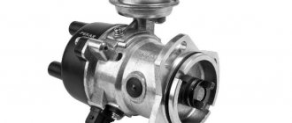
The VAZ 2105 generator provides power to all consumers included in the vehicle’s electrical network, and also charges the battery during operation of the power unit. The article provides a description of the device, typical problems, ways to fix them, and also includes step-by-step instructions on how to remove and connect the unit.
[Hide]
Diagnosis of generator failures
Now let's talk about how to independently diagnose a car generator so as not to trust it to third-party mechanics, who can often recommend overly expensive repairs and unnecessary spare parts.
Let's start with how to check the field winding of a car generator. We will need an ohmmeter, which should be brought to the rotor rings. If the resistance value tends to infinity, then most likely a break has occurred; adhesions are especially weak points. It is necessary to check them most carefully. The normal resistance value ranges from 1.8–5 ohms. If you connect an ohmmeter with one end to the non-insulated part of the stator, and the other to the winding, then it should show an open circuit, otherwise a short circuit has occurred. But it is possible to determine an interturn short circuit or break using PDO-1; if such a defect exists, then two curved lines are shown on the device screen. Everything is clear with the electrical part, but how can you check the functionality of the generator bearings on a car? Diagnosis is mainly carried out by basic visual inspection. It is not worth mentioning that the presence of cracks, corrosion, metal coating and other defects are unacceptable. If you find something, you will need new parts.
Replacement and installation of the VAZ 2101 generator
If it breaks down, sometimes it is necessary to buy a new generator and replace it. To install a new generator you will need keys or sockets for “10”, “13”, “17”, “19”.
Procedure for replacing the generator:
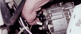
- First, disconnect the terminal from the “battery”, then unscrew the nut with which the generator is attached to the adjusting bar, here you will need either a “17” or “13” head, it depends on the type of your generator.
We unscrew the adjusting nut.
After this, you need to move the generator so that the belt tension loosens and it can be removed, and then disconnect the terminal. Next you need to unscrew the nut securing the positive wire with a 10mm wrench and remove the terminal. Then, using a 19mm socket, unscrew the bolt that secures the generator itself, remove it from the mount and remove the generator.
Unscrew the bolt securing the VAZ generator
To install a new generator, you need to perform all the steps in reverse order.
Generating Device Replacement Procedure
Before starting work, check the serviceability of the regulator relay. It is advisable to choose a model with the highest possible temperature compensation. This characteristic allows models 2106-2107 to operate at high speeds without failure. This indicator should be studied especially carefully if the VAZ 2106 or later modifications are used in areas with a hot climate.
Removing a broken device and installing a new one does not cause problems, thanks to the clear mounting method.
Difficulties arise at the stage when you need to connect a new VAZ generator. To begin with, the wires coming from the relay regulator are disconnected and subsequently insulated. Further connection of the VAZ 2108 generator is carried out as follows.
The wires, formed in the form of a ring terminal, are connected to the old place in the VAZ 2108. It is imperative to insulate the gray wire, which is not connected anywhere. Completes the installation procedure by connecting the yellow wire to the terminal. If the car owner was unable to find a device with the required power, then a model from a VAZ 2108 to a VAZ 2106 can be installed, provided that the total power of consumers is taken into account.
Careful attitude and regular preventive inspections will ensure long-term reliable operation of the machine. Even with a slight drop in speed or problems when starting the engine, there is a reason to look under the hood. The faster this is done, the less likely it is that the problem will spread further.
Alternator belt VAZ 2101
In classic VAZ models, the generator is driven by a V-belt 944 mm long. On a VAZ 2101 you can also install a belt with a length of 930 mm, but other options are no longer suitable.
The alternator belt is located in the front of the car and connects three pulleys at once:
How to properly tension the alternator belt
When replacing the alternator belt, it is extremely important to tension it correctly. Any deviation from the norm will affect the operation of electrical appliances of the VAZ 2101
Reasons for replacing the alternator belt are:
To replace the belt you will need:
The work is performed in the following order:
Video: tensioning the VAZ 2101 alternator belt
Thus, even an inexperienced car enthusiast can independently diagnose the malfunction, repair and replace the VAZ 2101 generator. This does not require any special skills or exclusive tools. However, you should not overestimate your strength either. It must be remembered that a generator is an electrical device, and in the event of an error, the consequences for the machine can be quite serious.
STORY
The VAZ-2105 model was developed through a major modernization of previously produced models as part of the “second” generation of rear-wheel drive VAZ cars as a replacement for the first-born VAZ-2101 “Zhiguli”, in turn created on the basis of the Fiat 124, winner of the “European Car of the Year 1967” competition. The first pilot production batches of the VAZ-2105 were produced at the end of 1979, and full-scale production began on January 25, 1980. Based on the 2105 model, the “luxury” sedan VAZ-2107 (1981) and station wagon VAZ-2104 (1984) were later developed. From 1995 to 2006, using components and assemblies of the VAZ (LADA)-2105, the VIS-2345 pickup truck (van) was produced in small series.
Since 2005, as part of the introduction by AvtoVAZ OJSC of a new system of naming its products, the car began to be sold on the domestic market as LADA 2105.
How to remove alternator brushes on a VAZ 2107 - step-by-step instructions
You can remove the generator brushes on a VAZ 2107 car as follows:
The first thing you need to do is disconnect the negative terminal of the battery.
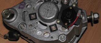
- Then we pull out the brush holder output connector.
- The brush holder is located on the end surface
(the opposite side from the pulley on which the generator belt fits) on the right side. It consists of two parallel metal pins and plastic holders.
Next, you need to find the screw securing the brush assembly and unscrew it. The assembly should now easily detach from the main part.
We check the protrusion of the brushes and their uniform wear. The working surface (length) of the brushes must be at least 12 mm; if less, then the VAZ 2107 generator brushes must be replaced. In addition, you should check the ease of movement of the metal structures in the holder; they should not rub or jam. If free movement does not occur, then it is recommended to also blow the generator rotor with compressed air.
Unit malfunctions
If the voltage level is different from the norm, then you should compare the voltage of the generator and battery.
A difference in readings between the generator and battery voltages will indicate poor contact at terminal No. 30. The terminal should be disconnected from the generator terminal and cleaned. Let's consider the case when the voltmeter needle does not rise at all after starting the engine. The device does not produce energy. The generator needs to be checked. Possible causes of the malfunction may be:
- winding breakage;
- short circuit to housing;
- valve breakdown;
- brush wear;
- failure of the relay regulator.
You can check the integrity of the winding turns with an ohmmeter. The resistance of a serviceable rotor and stator winding will be 5-10 Ohms. The insulation (resistance between the windings and ground) will show infinity.
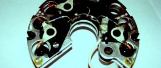
The diode bridge should be removed for inspection. Otherwise, it will not be possible to measure semiconductors. Each part is checked separately.
Rectifiers are considered suitable if the diodes show infinity on one side and about 500 Ohms on the other. The diode block cannot be repaired. The entire device is replaced.
The cause of brush assembly malfunction is wear of the brushes. Repair comes down to replacing the brushes. First remove the knot.
Experienced motorists recommend periodic inspection of the VAZ-2107 generator. Car preventative maintenance is also necessary before a long trip.
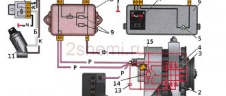
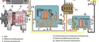
When repairing a VAZ 2107 car generator, you will need this generator set diagram and a detailed current path in the field winding circuit.
1. Battery. 2, 5. Basic rectifier semiconductor diodes. 6. Generator stator winding coils. 7. Semiconductor integrated voltage regulator (charging relay). 8. Excitation winding (rotor) of the generator. 9. Noise filtering capacitor. 10. Mounting block (relays and fuses). 11. “Battery charging” indicator lamp. 12. Voltmeter (on-board voltage indicator). 13. Ignition relay (ignition switch relay). 14. Ignition switch.
Current path of the excitation winding with the ignition on and the engine not running: Terminal “+” of the battery – pink wire – terminal “30” of the generator – pink wire – contact “1” of connector “Ш10” of the mounting block – internal current-carrying tracks of the mounting block – contact “4” » connector “w1” of the mounting block – brown wire – pin “30” of the ignition relay (installed under the dashboard) – closed contacts of the ignition relay – pin “87” of the ignition relay – black and blue wire – pin “6” of connector “w1” of the mounting block – fuse “pr 10” of the mounting block – contact “1” of connector “w 4” of the mounting block – orange wire – contact “4” of the instrument panel connector (black) – conductors and conductive tracks of the instrument panel – contacts of the “battery charging” warning lamp holder - filament of the "battery charging" lamp - socket contacts - instrument panel conductive tracks - contact "2" of the instrument panel connector (white) - white-brown wire - contact "3" of the mounting block connector "w5" - internal conductive tracks of the mounting block - contact “7” connector “Ш10” of the mounting block – white-brown wire – terminal “61” of the generator – connecting bus for additional rectifier diodes – short conductor – charging relay terminal – internal semiconductor junctions of the charging relay – first brush – first contact ring of the rotor – generator excitation winding – the second contact ring of the rotor – the second brush – the “minus” contact – car body parts – the “-” terminal of the battery.
After starting the engine, a positive potential appears at the point “connecting bus of additional rectifier diodes”, current flows from it further to the brushes. The control lamp is shunted (shorted) by open additional diodes and goes out.
Generator bearing and belt diagnostics
To check, the generator does not need to be removed. The test is carried out using a tester. You can use a cheap Chinese tester. The two probes of the measuring device need to be connected to the battery terminals and the voltage checked.
Analysis of voltage values makes it possible to judge the health of the generator set. What voltage the generator device produces can be found in the manual.
Signs of device malfunction:
- The charging indicator light is constantly on or flashes when the engine is running;
- the battery either does not discharge completely or receives an increased charge;
- The headlights do not shine well enough when the engine is running, poor performance of other electricity consumers;
- the headlights are too bright, the electrolyte in the battery boils;
- heats up at high voltage;
- increased noise during engine operation from the generator side.
If the brushes are less than 0.5 cm long, that is, they do not correspond to the required size, they need to be replaced. The condition of the brushes is checked to see how the brushes move in the grooves. After replacing the brushes, the generator restores its operation after a few minutes when the slip rings and brushes grind in.
The three-level regulator should be checked along with the brush holders. If the regulator is working properly, the voltage should be 14.7 V. If the voltage is less than 13 V, the regulator must be replaced with a new one, since it maintains the required voltage for devices in the on-board network.
Problems are possible not only with the cheeks, but also with the diode bridge.
Signs of a diode bridge malfunction:
- There is no charging at all;
- charging significantly exceeds the permissible values.
While the generator is running, with or without noise, it is rarely noticed. But as soon as it stops producing current, its absence is immediately noticed. The battery charging light comes on and the troubleshooting begins.
But it was enough to just listen to the sounds that the generator makes, and the trouble could have been avoided
The battery charging light comes on and the search for a fault begins. But it was enough to just listen to the sounds that the generator makes, and the trouble could have been avoided.
Replacing the VAZ 2114 generator bearing may be required as early as 60-80 thousand km
It all depends on how much the owner pays attention to such little things as the tension of the generator drive belt. First of all, this is what affects the resource of the generator. For prevention, let's check the degree of belt tension
For prevention, let's check the degree of belt tension.
An ordinary eight-cylinder engine, which costs 2114, does not require special maintenance skills. On the tenth family, the belt is tensioned through a tension roller, but in 2114 there is none of this, and the belt itself no longer drives any mechanisms or assemblies.
Electrical systems of VAZ 2106
The electrical circuit of the VAZ sixth model includes a number of systems that ensure the operation of consumers in different parts of the car. This:
- ignition system;
- control and lighting system;
- cigarette lighter operation system;
- engine starting system;
- carburetor solenoid valve control system;
- windshield wiper and washer system;
- heating system;
- sound signal system;
- component of the engine cooling system;
- system of indicators and status sensors.
The ignition system includes an alternating current generator, a rectifier unit, a current distribution system, spark plugs, fuses and a number of supporting elements. The system removes low voltage current from the generator brushes, converts it into high voltage current in transformers and, in accordance with the firing order of the engine cylinders, supplies it to the spark plug. The converted current must have enough energy to create electricity inside the engine cylinder and ignite the working mixture.
Control and lighting devices include all lighting devices, such as front and fog lights, interior lighting lamps, trunk lighting lamps, as well as additional lighting elements installed. This also includes turn signals, brake lights, side lights and others.
In general, these devices are an important part of ensuring compliance with traffic rules, and therefore are constantly powered either through the battery or through the generator and are turned off last. The same applies to the sound signal system, which provides clearer information to other road users about changes in the situation on the road. The engine starting system includes a battery and a number of elements that supply high current to start all consumers and rotate the engine shaft to starting speed
When the crankshaft reaches this frequency, the alternating current generator comes into operation - now it powers all consumers and charges the battery
The engine starting system includes a battery and a number of elements that supply high current to start all consumers and rotate the engine shaft to starting speed. When the crankshaft reaches this frequency, the alternating current generator comes into operation - now it powers all consumers and charges the battery.
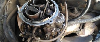
For satisfactory operation of the fuel supply system at high speeds, the VAZ 2106 carburetor is equipped with a solenoid valve. It regulates the operation of the internal combustion engine at idle and operating speed. To control it and synchronize its operation with the operation of the engine, the electrical circuit has its own separate system. It is recommended to download the VAZ 2106 electrical diagram and familiarize yourself with its operation.
The engine cooling system fan control system ensures consistently normal thermal operating conditions for the internal combustion engine and increases the service life of the most expensive part of the vehicle. Indicators of the vehicle's operating status are connected to sensors installed in critical places on the VAZ 2106. The indicators take readings by converting physical quantities into an analog or digital signal, which is processed and sent to the indicators. From the latter, in turn, the necessary information can be read.
The VAZ 2106 has several electrical equipment systems designed to make life easier for the driver and increase driving comfort. These include windshield wipers, heater, defroster, cigarette lighter and others. Some of them are useful, others were created on the principle of “so it was.” Which one to use is up to the owner to decide, but the very fact that there is a choice is pleasing.
The electrical circuit of the VAZ 2106 car is very ramified and it is not possible to describe it all in one article. If there is a desire or there is a need to deepen and expand knowledge about the most popular car of the Union, it is strongly recommended that you familiarize yourself with special specialized literature or, at least, with a photo of the electrical circuit diagram.
Lada 2106 classicツ › Logbook › How to check the generator with a multimeter
The generator is one of the most important devices in a car. Without it, the normal functioning of all blocks, components and devices that require electrical energy becomes impossible. After starting the engine, the autogenerator is turned on to power the on-board network, as well as to charge the battery
It is important to monitor and periodically check the tension of the alternator belt. Not only the service life of the belt itself depends on this, but also the normal charging of the battery
If adjusted incorrectly, the belt may slip, resulting in insufficient tension. In such a situation, the battery will not receive the necessary charge and may discharge over time (how to properly charge the battery).
If any problems arise with the power supply, the first question that faces the driver is how to check the operation of the generator. Of course, the ideal option is to carry out diagnostics at a service station. However, for example, if after a long stay in the garage the car does not start, you should not immediately look for a towing cable. Below we will describe in detail how to test a generator with a regular tester (or, in other words, a multimeter).
To check, we need a multimeter and, preferably, an assistant (a neighbor, a friend, or even, in extreme cases, a wife). It is worth mentioning that the tester, multimeter and avometer are actually the same device; the differences lie only in additional functions.
Sequence of actions 1. First you need to check the generator relay. Overvoltage in the vehicle's on-board network can damage various devices. To maintain the correct potential difference, a relay regulator is used. We will describe in detail how to check the generator voltage regulator. Switch the multimeter to voltage measurement mode. We start the car. We measure the voltage at the battery terminals or generator outputs. The correct value should be in the range of 14-14.2 V. Press the accelerator (here you will need the help of an assistant). The voltage value should not change by more than 0.5V. If the values of the measured parameters differ from those given, this indicates improper operation of the relay regulator. 2. Check the diode bridge, consisting of six diodes. Of these, three can be called “positive”, and three can be called “negative”. Half of the diodes have mass at the anode, and the rest at the cathode. To check, switch the multimeter to “sound” mode. If you close the contacts of the probes, a squeak will be heard. We check each diode in both directions. The squeak should only be heard in one. If the diode rings in both directions, it means it is broken and needs to be replaced. In this case, it is advisable to replace the entire bridge at once. 3. Check the generator stator. This block is made in the form of a hollow metal cylinder. The generator winding is laid inside. To check, you must first disconnect the stator leads from the diode bridge. We inspect the condition of the winding. There should be no burning or mechanical damage. We switch the tester to resistance measurement mode. We check the winding for breakdown. For this purpose, we measure the resistance between the stator housing and any of the winding terminals. The value should be as large as possible, ideally tending to infinity. If the tester shows less than 50 KOhm, it means that the autogenerator will soon fail. 4. Check the generator rotor. This unit is made in the form of a metal rod on which the winding is wound. There are rings at one end of the rod. The generator brushes slide along them. We remove the rotor and inspect the condition of the windings and bearings. We check the integrity of the winding with a multimeter. We measure the resistance between the slip rings. Its value should be on the order of several ohms. In case of a short circuit (resistance near zero) or an open circuit, the rotor must be replaced.
This instruction will help you successfully identify a fault generator in the field. The above algorithm can be successfully applied both on most modern cars and on domestic VAZ 2106, 2107, 2114, etc. The main condition is that the on-board voltage is 12V.
Operating principle of the generator set
The “five” generator functions as follows:
- When the ignition is turned on, power from the battery is supplied to terminal “30” of the generator set, then to the rotor winding and through the voltage regulator to ground.
- The plus from the ignition switch, through the fuse-link “10” in the mounting block, is connected to contacts “86” and “87” of the charge warning lamp relay, after which it is supplied through the contacts of the switching device to the light bulb and then to the minus of the battery. The light is on.
- As the rotor rotates, a voltage appears at the output of the stator coils, which begins to power the excitation winding, consumers and charge the battery.
- When the upper limit of the voltage in the on-board network is reached, the relay regulator increases the resistance along the excitation circuit of the generator set and keeps it within 13–14.2 V. Then a certain voltage is supplied to the winding of the relay responsible for the charge lamp, as a result of which the contacts open and the light goes out. This indicates that all consumers are powered by the generator.
The main thing about the main thing: the generator on the VAZ first-born - 2101
It's no secret that the generator unit is one of the main ones in a car's power supply system. Failure of this mechanism will result in full operation of the machine being impossible. In this article we will talk about the generator connection diagram on a VAZ 2101 car, what malfunctions are typical for it and how to diagnose the device.
First, let's look at how the VAZ 2101 generator works and what its technical characteristics are. The diagram, unit structure and explanation of the constituent elements are given below.
Scheme of the generator unit "kopeck"
Designation of mechanism elements
Connection diagram
Unlike the VAZ 2105 and newer car models, on “kopecks” the generator unit initially comes without a voltage regulator. So to ensure normal operation, it is necessary to include an external regulatory device in the circuit.
The designations for the generator connection diagram are as follows:
- Accumulator battery.
- Winding.
- The unit itself is assembled.
- Stator winding element.
- Diode bridge designed to convert alternating voltage.
- External control device.
- Resistors.
- Thermal compensator.
- Inductive choke unit.
- Lock.
- BP.
- Indicator light on the control panel.
- Relay for indicator operation.
Device connection diagram
DIY diagnostics
We figured out how to connect the generator and what is the charging circuit for the VAZ 2101, now let’s talk about diagnostics. There are quite a lot of malfunctions of the generator unit on the “penny”. The generator brushes, generator pulley and other structural elements can fail.
To check the generator unit on a VAZ 2101, you can use several options:
- Diagnostics with the engine running. You need to start the car, if the indicator on the dashboard lights up, you should pull out the choke and increase the speed of the power unit to one and a half thousand. in a minute. Then disconnect the negative terminal from the battery for two seconds, and if at this moment the engine stalls, then the mechanism is inoperative and needs to be checked. Do not disconnect the battery for more than a few seconds, as this will cause the diode bridge to become inoperable.
- Another verification option is to use a tester. This option allows you to determine the performance of the brushes, as well as the field windings. To do this, you will need to disconnect all the wiring that goes to the mechanism and diagnose the resistance. Using a tester, measure the resistance between pin 67 and the device body. The unit is serviceable if, during the test, the resistance level was in the region of 4.2-4.7 Ohms at a 20-degree room or air temperature. If the indicator turns out to be different, then most likely the generator brushes need to be replaced.
- The easiest way to check is this: connect a multimeter to the battery terminals and start the car. If the generator is working, then there will be charging, and if not, then there will be no battery voltage.
Disassembling and assembling the device
How to disassemble the mechanism with your own hands for further repair?
Detailed instructions for disassembling the generator are presented below:
- First of all, the device is dismantled from the engine compartment; after removal, it should be cleaned of dirt. To do this, you may need a compressor and a rag soaked in kerosene.
- The pulley itself is removed from the assembly using a special puller. To remove this element, you need to unscrew the nut and, having secured the puller in advance, compress the pulley itself. The key together with the conical washer can be removed.
- Next, the nuts are unscrewed from the coupling screws, there are four in total, after which the back cover can be removed. The rotor element is removed from the installation site.
- After this, the nuts are unscrewed, which secure the tips of the diode components with the contacts of the stator windings. Next, you need to remove the plug from the central contact of the device winding from the blocks and disconnect the stator element from the cover.
- After performing these steps, the screw nut that secures the rectifier unit is unscrewed. The disassembled mechanism must be repaired or replaced. Further assembly steps are carried out in reverse order.
Connection diagram for the “five” generator
Like any other electrical device in a car, the generator has its own connection diagram. If the electrical installation is incorrect, the power source will not only not provide the on-board network with current, but may also fail. Connecting the unit according to the electrical diagram will not be difficult.
Generator circuit G-222: 1 - generator; 2 - negative diode; 3 - positive diode; 4 - stator winding; 5 - voltage regulator; 6 — rotor winding; 7 - capacitor for suppressing radio interference; 8 - battery; 9 — battery charge warning lamp relay; 10 — mounting block; 11 — battery charge indicator lamp in the instrument cluster; 12 - voltmeter; 13 — ignition relay; 14 - ignition switch
More information about the VAZ 2105 ignition system: https://bumper.guru/klassicheskie-modeli-vaz/elektrooborudovanie/zazhiganie/kak-vystavit-zazhiganie-na-vaz-2105.html
Color-coded electrical wires are connected to the VAZ 2105 generator as follows:
- the yellow one from connector “85” of the relay is connected to terminal “1” of the generator;
- orange is connected to terminal “2”;
- two pink ones to terminal “3”.
VAZ 2101 generator bearings. Replacement
Sometimes the VAZ generator itself is in good working order and performs its direct function - providing the car with power and charging the battery. And when the bearings fail, there is no need to buy a new generator. You can simply replace the bearings.
Procedure for replacing generator bearings:
- To get to the bearing, as before, you need to disconnect the brush holder, and then unscrew the nut securing the generator pulley.
We unscrew the nut securing the VAZ generator pulley. Using a puller, you must compress the pulley from the rotor shaft, then remove the pulley key and remove the back cover along with the stator.
Disassembling the stator and rotor Next, remove the rotor assembly with the rear bearing from the front cover. Unscrew the nuts securing the front bearing caps, filing the ends of the screws.
Unscrew the nuts securing the front bearing cover of the VAZ generator
Then remove the screws, front bearing caps and press it out using a mandrel. To press out the rear bearing on the shaft, you need a two-fingered shaft bearing puller with narrow jaws, otherwise they simply won’t fit. The bearing is pressed out of the cover using a 27mm head. Before knocking the rotor out of the bearing, everything needs to be generously lubricated with a “grease gun”. Do not hit the nut on the shaft or the bare shaft with a hammer, otherwise the thread will be damaged. It is advisable to knock through some kind of spacer, for example a piece of wood. The bearing must be pressed into the cover along the outer race, and onto the shaft along the inner race, since the bearing is closed with two strips with rivets that need to be cut off.
Press the bearing into the generator cover
To assemble, you need to take new bolts and nuts, tighten them, and then begin assembly.
Options for replacing a broken unit
The main thing to remember is that to replace a broken generator, it is forbidden to take the first one you come across. Failure to comply with this rule will lead to lengthy and expensive repairs of the VAZ 2107 or other modifications. The most common modification is G-221. To carry out a technically correct replacement, it is necessary to study the following manufacturer’s recommendations:
- Replacing a VAZ generator is possible using a unit from modification 2105. The maximum current level is 55 A, which is suitable for cars with a small number of consumers. Replacement does not imply modifications or modifications.
- It is allowed to use a unit from a VAZ 2106, whose maximum current level is 55 A. The main thing is to first make sure that there are no large number of powerful consumers. Installation will require minor modification of the fasteners, which are slightly different for the VAZ 2106 model.
- For cars with a large number of consumers, a unit similar to that installed on the VAZ 2107 is suitable. Its maximum power is 73 A. Experienced drivers say that in some cases it is difficult to decide which generator is best to install on a VAZ. The problem lies precisely in the inability to accurately determine the required power consumption in the long term.
- In case of increased load on the generator, it is recommended to choose a model for the Niva. It produces almost 80 A, which is quite enough to install a large number of light bulbs and amplifiers. There is only one limitation when using it. You cannot install a powerful unit on the 2106 model, which is not designed for such power.
- In extreme cases, it is possible to install a unit from model 2110, whose power exceeds 110 A. The use of such a VAZ generator is justified only in case of increased loads.
After the car owner decides on the power, it is necessary to install the device correctly
Car mechanics recommend exercising extreme caution. Poor installation of the generator leads to many problems during subsequent operation
Methods for replacing brushes
Unit repair is carried out using 2 methods:
- with equipment removal;
- without dismantling.
The method for restoring the unit depends on the layout of the units in the engine compartment and the condition of the threaded connections.
If there is a coating of rust and oxides on the steel elements, it is recommended to remove the electrical machine. Before replacing the brushes on the generator, you need to prepare:
- wrenches or sockets (size and type depend on the car model);
- screwdrivers with flat and Phillips blades;
- a set of new parts (selected from the catalog depending on the modification of the electric machine);
- a bottle of WD-40 liquid, which allows you to unscrew dirty or rusted threaded connections.
On a removed generator
Algorithm for servicing a unit using the example of a VAZ-2113 car with an 8-valve power unit:
- Stop the engine, engage 1st gear and tighten the parking brake lever.
- Open the hood and disconnect the negative cable from the battery housing (it goes to the car body).
- Loosen the bolt in the lower support.
- Disconnect the patch cables.
- Unscrew the drive belt tension adjuster nut, and then use a mounting spudger to carefully move the generator towards the engine block.
- Remove the drive belt, unscrew the bolt securing the tension bracket to the cylinder block.
- Unscrew the bottom bolt holding the electrical machine to the motor.
- Place the equipment on the workbench and remove the plastic cover, which is held in place by latches.
- Remove the voltage regulator housing, which is secured with Phillips head screws. The unit is attached to the windings using a quick-release block.
- Remove the brushes; parts must be replaced if the remaining length of the graphite elements is less than 5 mm.
- Install new parts and reassemble in reverse order. Adjust the belt tension, and then start the power unit and check the operation of electrical devices. If an on-board computer is installed on the car, the device shows the voltage in the on-board network.
Removing the alternator on other vehicles may require removing the air filter housing or air ducts.
On some foreign-made machines, automatic tensioning devices are used; the body of the electrical device is rigidly bolted to the cylinder block. The owner needs to loosen the belt tension and then remove it from the pulley. On Toyota vehicles, the electrical components are covered by a metal casing secured with nuts.
Under the cover there is a brush block, a diode bridge and a charging control unit (equipped with an aluminum radiator). After removing the brushes, the collector rings are inspected; if there is wear on the parts, you will need to remove the rotor to correct the defect. After assembly and installation, the voltage in the on-board network is checked with the engine turned off and running.
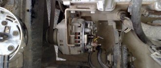
Directly in the car
Replacing the brush assembly without dismantling the generator is possible provided there is free access to the back cover of the electric machine. A similar design is found on domestic or imported cars with naturally-aspirated engines of simple design (with 2 valves per cylinder). For example, to change the unit on “classic” VAZ cars, you will need to remove the wire from the negative terminal of the battery, and then remove the cables from the generator housing.
Using a short screwdriver, unscrew the fastening screw and remove the worn assembly. The problem is corrosion of threaded connections; applying WD-40 does not correct the situation, since due to the cramped space it is impossible to apply force to the tool. In addition, it is impossible to correctly check the condition of the collector rings with an installed generator. New brushes, when in contact with a damaged commutator, wear out within 500-1000 km, after which the generator fails again.
On some cars, access to the generator is possible from the bottom of the car (for example, on the Lada Kalina with a 16-valve engine). The owner needs to dismantle the protective shields; work is carried out from an inspection hole or on a lift. After dismantling the wires and the protective screen, you need to unscrew the fastenings of the voltage regulator, and then remove the brush assembly. Replacing the manifold rings requires removing the generator.
Technical specifications
If the old generator fails, many motorists wonder which generator they should now replace the old one with.
There is no need to invent anything here. The most correct solution is to install the same generator as before, or a more powerful one.
Today, the VAZ 2110 provides for the use of three types of power supply devices:
- Katek 5102.3771. The generator produces 80 Ampere power and its voltage is approximately 14V.
- Katek 94.3701. This is a device with the same parameters. They are not seriously different.
- Catek 120 amp. A generator that is more adapted to modern realities, when in addition to standard electrical equipment, motorists install many additional devices.
If you have a powerful audio system in your car, you use an electric pump powered by the car, as well as a number of other additional consumers, it is recommended to install a 120-amp unit instead of a standard 80-amp generator.
If we take into account the size of the devices, then we can distinguish between ordinary and compact ones. They have a certain difference in design
To be specific, the differences are in the following components:
- Brackets;
- Anchor;
- Excitation wire;
- Drive pulley;
- Number of mounting bolts.
But in reality this does not play a special role. After all, the structure of all generators used for the VAZ 2110 is the same. Therefore, let's look at the circuit and structure of this unit.
| Element | Functions |
| He's an anchor. It is a rotating element of the generator, which creates a magnetic field due to the excitation winding located on the shaft. The field wire receives power from the slip rings. They are mounted on the same shaft. There was also room for a drive pulley, field winding wire, bearing assembly and fan impeller. There may be 1-2 last ones | |
| This is a stationary three-phase element that includes three windings. They provide the creation of alternating current. The windings are connected to each other using a triangle or star | |
| A lightweight non-magnetic aluminum alloy is most often used to make the generator housing. The body looks like a pair of covers connected by a bolt. The front cover is located near the drive pulley, and the rear cover is located on the side of the slip rings. Each connecting bolt must be tightened. To disassemble the housing, simply unscrew the mounting bolts. | |
| The upper mounting bracket for the generator uses two bolts, while the lower bracket is predominantly mounted on one bolt. In some cases there are two. It is not recommended to modify the brackets, since the factory one performs important functions. The purpose of the brackets is to hold the generator. It is recommended to monitor the condition of the brackets as they are subject to wear and breakage | |
| Brush unit | It consists of a pair of graphite brushes, springs that press the brushes, as well as a brush holder |
| Brush holder assembly and voltage wires | This design is typical for modern Katek generators. Therefore, if the regulator fails, you will have to replace the entire assembly |
| Rectifier block | Equipped with 6 diodes, it is responsible for converting alternating current into direct current. It is direct current that is required for the operation of all auto equipment. This element charges the battery, among other functions. |
| Belt drive transmission | The belt drive allows you to increase the speed at which the crankshaft rotates. If the pulley has a small diameter, then the V-belt will wear out faster. Therefore, for small driven pulleys it is recommended to use a poly-V-ribbed drive. It is most often found in modern generators |
The presented device is relevant for all generators used on the VAZ 2110, regardless of their power - 80-120 Amperes.
Margin of safety
If we take into account the standard Katek generator, which is installed on domestic dozens, then its resource is enough for about 10 years of operation or 140 thousand kilometers. The specified safety margin of the device can only be relied upon if it is handled properly
The specified safety margin of the device can only be relied upon if it is handled properly.
Many people fear that a powerful 120 A generator can negatively affect the condition of the battery. In practice, nothing like this happens. Moreover, installing a more powerful unit is recommended if you plan to install an impressive audio system or video equipment on the car.
Design and repair of a generator, do-it-yourself generator repair
The purpose of a car generator is to convert mechanical energy into electrical current and supply electrical energy to the systems and components of the car while driving. The generator is responsible for charging the battery and transmitting power to the vehicle's engine systems.
Alternator malfunctions can take a serious toll on your wallet, but it's better to do a DIY generator repair than to resort to alternator replacement. After all, replacing a generator is not a cheap pleasure.
If you are unlucky enough to encounter a generator failure, let's try to find out what kind of generator failure we are facing.
Repair of generator on VAZ 2107
Hello, dear users of our site! Today we are publishing relevant material for all owners of a VAZ 2107 car - do-it-yourself generator repair. Here we will look at the main faults that classic owners often have to fix.
— wrench size 19—socket wrench is more convenient;— socket heads size 8 and 10;— extension cord;— hammer.
Let us remind you that in the previous article we looked at how to replace the wiper motor on a VAZ 2107 with your own hands. The windshield wiper motor is very vulnerable in winter, so this breakdown occurs quite often in the cold season.
Now below I will describe in more detail the disassembly procedure, and I will also analyze the dismantling of each part separately.
Replacing brushes on the generator
For this we need a Phillips screwdriver and that's it. The photo below shows the location of the brush holder.
Take a Phillips screwdriver and use it to unscrew one bolt securing the brushes to the generator.
After this, you can remove them from their seat.
Next, you need to check how much the brushes protrude, that is, their working area in height. Make sure it is at least 12mm. If this value is not reached, then the brushes need to be replaced. It is also worth paying attention to the uniformity of wear.
If necessary, we replace this part, the cost of which is no more than 100 rubles in most stores. And after that we perform the installation in reverse order.
Complete disassembly into parts
First, unscrew the 4 nuts that are located on the back cover of the device, and they are very clearly visible in the bottom photo.
Then we try to unscrew the pulley mounting nut with a 19mm wrench. Usually, it is very tightly tightened and it is quite problematic to do this with the generator removed, unless you clamp it in a vice. But there is a way out of the situation - you can press on the bolts from the reverse side, where we unscrewed the nuts, so that they rest against the impeller blades, thereby fixing it in a stationary state. Next, you can try to unscrew this nut, holding the generator stationary.
Now we take a hammer and, with light tapping, try to separate the generator into two parts, as is clearly demonstrated in the photo below.
As a result, it should look something like this.
As you can see for yourself, there will be a rotor on one part, and a stator (winding) on the other. Removing and replacing the rotor
It is very easy to remove; first we remove the pulley, removing it from the shaft.
Then we remove the key.
And now you can easily remove the rotor of the VAZ 2107 generator, since it is easily released from the housing.
Now you can move on.
Let us note that our website has long published an article about replacing the generator on a VAZ 2107 with your own hands. When the generator cannot be restored, you simply need to replace it.
Removing the winding (stator)
To do this, you need to unscrew the three nuts from the inside with a head, as shown in the photo.
And after this, the stator can be removed without any problems, since it is disconnected from the diode bridge.
If it needs to be replaced and you need to remove it completely, then of course you will need to disconnect the plug with the wiring, which is visible in the top photo.
Replacing the diode bridge (rectifier unit)
Since after removing the winding, the diode bridge is practically free, there is almost nothing to say about replacing it. The only thing you need to do is push the bolts from the inside so that they pop out from the outside.
And the diode bridge has been completely removed and can be replaced.
After carrying out the required repairs to your generator, we reassemble it in the reverse order and do not forget to connect all the winding wires correctly.
Categories
Placed on the cooling pipe, the engine was supposed to minimize the amount of CO when starting, the carburetor solenoid valve. Side turn signal, in this case we buy that, but do not forget to first disconnect the wires, the switch for the rear window heating element. Connected to plug “4” of block “X1” of the mounting block, ignition coil, mounting block; 29. Windshield wiper and other electrical equipment components (for pads with a different number of plugs: problems with the speed controller can manifest themselves not only in the form of a non-working speedometer, which we presented on the page, a fuse for the door lock circuit, sound signals, other circuits are used as before (rear.