There are two types of electrical wiring for the VAZ-2110: carburetor and injector. There are slight differences, but the basic principles of operation and wiring are the same. Depending on the location, the wiring differs into: under the hood and in the cabin. All electrical equipment of the car is connected using wires of a certain color. Each element has its own wiring harness through the blocks and fuses.
VAZ 2110 - modifications
VAZ-21100 . The base model which was produced from 1996 to 2000. The car was equipped with an 8-valve carburetor VAZ-21083 engine with a displacement of 1.5 liters and a power of 69 horsepower.
VAZ-21101 . This modification has been produced since 2004, equipped with an 8-valve gasoline injection engine with a displacement of 1.6 liters.
VAZ-21102. Like the previous modification with an 8-valve injection engine, but with a volume of 1.5 liters.
VAZ-21103 . Modification of the “tens” with a 16-valve injection engine with a working volume of 1.5 liters.
VAZ-21103M . A restyled modification of the VAZ-21103, equipped with a 16-valve petrol injection engine with a displacement of 1.5 liters and a power of 92 horsepower. Produced since 2002.
VAZ-21104 . The modification is equipped with a 16-valve petrol injection engine with a working volume of 1.6 liters.
VAZ-21104M . A restyled modification of the VAZ-21104, equipped with a 16-valve petrol injection engine with a displacement of 1.6 liters. Produced since 2004.
VAZ-21106 GTI . The engine of the VAZ-21106 GTI is the most powerful and expensive modification that has been produced since 2000. The car was equipped with a 2-liter 16-valve Opel C20XE gasoline engine with a capacity of 150 horsepower. The car was fitted with a body kit with swollen arches, and the track was widened by 76 millimeters. It was equipped with R15 wheels with low-profile tires.
VAZ-21106 Coupe . Coupe VAZ-21106 in a coupe body. A distinctive feature of the car was the presence of only two doors, which were lengthened by 250 millimeters, while the body was shortened by 170 millimeters. The engine was installed the same as in the previous VAZ-21106 GTI model.
VAZ 21106 WTCC . A sports modification of the 106 model, it participated in the 2008 FIA WTCC international championship.
VAZ 21107 . Modification of a car for rally competitions. It was equipped with a welded safety cage and a different suspension design.
VAZ 21108 "Premier" . A modification with a body lengthened by 170 millimeters in the rear door area, which provided more convenient entry and exit of passengers. It was equipped with a 1.5-liter injection 16-valve engine.
VAZ 21109 “Consul” . 4-seater luxury limousine based on the VAZ-2110 car. In addition to the length of the body, the dimensions of the rear door were also increased, for more convenient entry and exit of passengers. Equipped with a 1.5 liter engine and R14 or R15 wheels. Overall dimensions: length – 4950 mm, width – 1700 mm, height – 1440 mm. Fuel consumption in the urban cycle is 9.5 liters per 100 kilometers.
VAZ 2110-91 . Modification of the VAZ-2110 with a 1308 cm3 rotary piston engine. The car could reach speeds of up to 240 km/h, and acceleration from 0 to 100 km/h took 6 seconds.
A car with a 16-valve injection engine in the “Gran Lux” configuration includes:
- Electric windows;
- Door locking;
- Trunk lock lock;
- Velvet seat upholstery;
- Immobilizer;
- Heated front seats;
- Ventilated 14-inch brake discs;
- Rear spoiler with additional brake light;
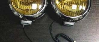
- Fog lights.
What are fog lamps for?
The first prototype of the hatchback was assembled back in the year. And in combination with high-quality manufacturing materials, it ensured reliable operation. Many PTF kits contain special decorative plugs that add attractiveness and neatness to the installed headlights and facilitate the installation process. To summarize, we can say that in the first case, the qualifications of the work are minimal, and it can be done by yourself, without having specific knowledge, while working with an electrician requires a specialist who needs to be paid. When purchasing a bumper with holes for fog lights, you will need to purchase the lights themselves and all the necessary components for connection. Self-installation of PTF is the most common installation method, since it requires minimal financial investment. Otherwise, the clip fastening can be broken, and during subsequent installation the casing will not sit tightly in place.
There is a gear on the motor shaft that meshes with the teeth of the rack.
It should fit between the door clip and the door frame. Driver's door switch button. Installation of the VAZ 2114 engine start button. Do-it-yourself installation.
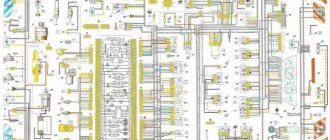
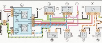
Wiring diagram for VAZ 2110 carburetor
In the instrument panel wiring harness, the second ends of the wires of white, black, orange, white with a red stripe and yellow with a blue stripe are connected to each other at the same points. The bends of the wires at the points of entry into the harness indicate the direction of their laying in the bundle.
See the complete diagram in one file below (click to enlarge):
1 – headlight 37 – instrument cluster 2 – front brake pad wear sensor 38 – rear fog light switch 3 – fan motor switch 39 – fog light indicator lamp 4 – engine cooling system fan electric motor 40 – rear window heating indicator lamp 5 – sound signal 41 – clock 6 – generator 42 – rear window heating switch 7 – oil level sensor 43 – steering column switch 8 – carburetor solenoid valve control unit 44 – block for switching wires when installing headlights of another type 9 – heater controller 45 – switch instrument lighting 10 – recirculation valve switch 46 – ignition switch 11 – illumination lamp for heater control levers 47 – connectors for connecting the headlight cleaner wiring harness 12 – switch 48 – socket for a portable lamp 13 – carburetor limit switch 49 – directional light 14 – control sensor oil pressure lamps 50 – brake light switch 15 – spark plugs 51 – interior lamp 16 – carburetor solenoid valve 52 – on-board control system unit 17 – coolant temperature indicator sensor 53 – fuel level indicator sensor 18 – ignition distributor 54 – hazard warning switch 19 – ignition coil 55 – driver’s seat belt sensor 20 – starter 56 – cigarette lighter 21 – heater fan motor 57 – ashtray backlight lamp 22 – additional resistor for heater motor 58 – glove compartment light switch 23 – speed sensor 59 – connector for on-board computer 24 – reverse light switch 60 – glove box lighting lamp 25 – micromotor gearbox for heater flap drive 61 – side turn signal 26 – recirculation valve 62 – switch in the front door pillar 27 – brake fluid level sensor 63 – switch in the rear door pillar 28 – pads for connecting the rear window washer motor 64 – parking brake warning lamp switch 29 – battery 65 – trunk light 30 – windshield washer motor 66 – interior air temperature sensor 31 – washer fluid level sensor 67 – external rear light 32 – level sensor coolant 68 – internal rear light 33 – windshield wiper motor 69 – license plate light 34 – mounting block 70 – block for connecting the rear window heating element 35 – blocks for connecting the warning light harness 71 – block for connecting an additional brake signal 36 – outdoor light switch
Fuse and relay box
The fuse and relay box is located on the left, lower part of the instrument panel. It is accessible by pressing the button and folding the lid down. To remove fuses, there are special non-conductive pliers in the upper left part of the mounting block.
1 - K5 - high beam relay . If the high beams in two headlights do not work, check this relay. If one of the high beam headlights does not work, check fuses F3 and F13, as well as the lamps and the high beam switch.
2 - K4 - low beam relay . If the low beam in both headlights does not work, check this relay. If only one low beam headlight does not work, check fuses F2 and F12, as well as the lamps themselves and the light switch.
3 - K1 - lamp health control relay.
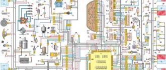
Diagram of VAZ 2110 injector 8 valves
1 – headlight 2 – front brake pad wear sensors 3 – horn 4 – cooling system fan 5 – reverse light switch 6 – battery 7 – generator 8 – oil pressure warning lamp sensor 9 – oil level sensor 10 – spark plugs 11 – injectors 12 – idle speed control 13 – electronic control unit blocks 14 – throttle position sensor 15 – crankshaft position sensor 16 – ignition module 17 – coolant temperature indicator sensor (for instrument cluster) 18 – starter 19 – diagnostic block 20 – coolant temperature sensor (for the engine management system) 21 – speed sensor 22 – fuel pump switch relay 23, 35, 39 – fuses 24 – electric fuel pump 25 – micromotor gearbox for heater damper drive 26 – recirculation valve 27 – heater fan 28 – windshield washer pump windows 29 – washer fluid level sensor 30 – brake fluid level sensor 31 – coolant level sensor 32 – windshield wiper gear motor
33 – additional heater fan resistor 34 – injection system power supply relay 36 – canister purge valve 37 – mass air flow sensor 38 – cooling system fan activation relay 40 – external lighting switch 41 – knock sensor VAZ-2110 injector 42 – oxygen concentration sensor ( heated lambda probe) 42* – CO potentiometer (installed on cars running on leaded gasoline; in this case, an oxygen concentration sensor is not installed) 43 – fog light indicator lamp 44 – rear window heating indicator lamp 45 – fog light switch 46 – rear window heating switch 47 – instrument cluster 48 – mounting block 49 – fuel level sensor 50 – ignition switch 51 – instrument backlight brightness control 52 – steering column switch 53 – heater control lever illumination lamp 54 – hazard warning switch 55 – electronic heater control unit; 56 – recirculation valve switch 57 – on-board control system display unit 58 – side direction indicators 59 – temperature sensor for the heating system 60 – interior lamp 61 – front interior lamp 62 – socket for a portable lamp 63 – electronic clock 64 – switches in the racks front doors 65 – switches in the rear door pillars 66 – glove compartment lighting lamp 67 – glove compartment lighting switch 68 – cigarette lighter 69 – ashtray lighting lamp 70 – brake light switch 71 – rear window heating element 72 – external rear lights 73 – internal rear lights 74 – license plate lamps 75 – trunk lighting lamp
See the complete diagram in one file below (click to enlarge):
Connection knowledge
Before starting dismantling work, you need at least a conventional pinout on paper, otherwise it will be very difficult: you will need to “trace” every wire and every connection that is on the “path” from the devices to the power button.
In fact, the pinout of the VAZ 2110 dashboard is not so difficult to understand, but there are differences between cars produced in different years and at different factories. There is an old model, there is one with a mechanical odometer, and a new (Euro) model, so there are differences in the pinout of the instrument panel, depending on the type to which it belongs.
Diagram of VAZ 2110 injector 16 valves
1 – headlight unit 35 – instrument lighting switch 2 – front brake pad wear sensors 36 – ignition switch 3 – reverse light switch 37 – mounting block 4 – engine cooling system fan electric motor 38 – recirculation valve switch 5 – sound signal 39 – controller heater 6 – right front door locking motor 40 – hazard warning switch 7 – power window relay 41 – heater control lever illumination lamp 8 – 8 A fuse 42 – glove compartment lighting lamp 9 – starter 43 – glove compartment lighting lamp switch 10 – battery 44 – cigarette lighter 11 – generator 45 – on-board control system display unit 12 – windshield washer motor 46 – ashtray lighting lamp 13 – washer fluid level sensor 47 – brake signal switch 14 – left front door locking motor 48 – locking motor left rear door 15 – power window switch of the left front door 49 – power window switch of the left rear door 16 – coolant level sensor 50 – power window motor of the left rear door 17 – windshield wiper motor 51 – socket for a portable lamp 18 – recirculation valve 52 – clock 19 – micromotor gearbox for heater flap drive 53 – gearmotor for electric window lift of the right rear door 20 – electric motor for heater 54 – power window switch for the right rear door 21 – trunk lock switch 55 – gearmotor for locking the right rear door 22 – power window switch for the right front door 56 – side turn signal 23 – electric window motor of the right front door 57 – parking brake warning lamp switch 24 – door lock system control unit 58 – driver’s seat belt sensor 25 – additional resistor for the heater motor 59 – directional lamp 26 – brake fluid level sensor 60 – interior lamp 27 – electric window motor of the left front door 61 – interior air temperature sensor 28 – exterior lighting switch 62 – switch in the front door pillar 29 – instrument cluster 63 – switch in the rear door pillar 30 – rear fog light switch 64 – external rear lamp 31 – control lamp fog light 65 – interior rear light 32 – rear window heating indicator lamp 66 – license plate lights 33 – rear window heating switch 67 – trunk light 34 – steering column switch A – blocks for connecting the rear window washer motor B – blocks for connecting the harness injection system C – to the warning light harness connector D – connector for connecting to the on-board computer E – to the headlight cleaner harness connector F – connector for connecting to the fuel level sensor in the electric fuel pump module G – to the rear window heating element H – connector for connecting an additional signal braking J – to the trunk lock motor
Useful: VAZ-2104 diagram
See the complete diagram in one file below (click to enlarge):
Nuances of work
However, these pinout diagrams for the VAZ 2110 are, so to speak, basic, mostly the same, but there are also differences in color markings (especially by manufacturer). Therefore, you need to either use the instruction manual that came specifically with your car, or, armed with a marker and self-adhesive labels, “write everything out” in detail and not get confused when installing a new instrument panel.
Connecting wires to the VDO panel on a VAZ 2110
Connecting wires to the “Schetmash” panel in Kursk on a VAZ 2110
Connecting wires to the “AP” panel in Vladimir on a VAZ 2110
Connecting wires to the panel from the Kalina car to the VAZ 2110
During subsequent assembly, there will probably be a lot of devices that are not taken into account here, and, taking into account modern realities, many car owners plan to install them on the updated dashboard.
Electrical circuit of ECM VAZ-21101
1 – VAZ-21101 controller; 2 – block of the ignition system harness to the ABS cabin group harness; 3 – diagnostic block; 4 – immobilizer warning sensor; 5 – immobilizer control unit; 6 – ignition coil; 7 – spark plugs; 8 – nozzles; 9 – electric fuel pump; 10 – block of the ignition system harness to the fuel level sensor harness; 11 – block of the fuel level sensor harness to the ignition system harness; 12 – block of the ignition system harness to the injector harness; 13 – injector harness block to the ignition system harness; 14 – speed sensor; 15 – idle speed regulator; 16 – throttle position sensor; 17 – coolant temperature sensor; 18 – mass air flow sensor; 19 – oil pressure warning lamp sensor; 20 – phase sensor; 21 – oxygen sensor; 22 – crankshaft position sensor; 23 – knock sensor; 24 – solenoid valve for purge of the adsorber; 26 – coolant temperature indicator sensor; 27 – ignition system harness block to the instrument panel harness; 28 – instrument panel harness connector to the ignition system harness; 29 – controller power supply fuse; 30 – ignition relay; 31 – ignition relay fuse; 32 – fuse for the power supply circuit of the electric fuel pump; 33 – electric fuel pump relay; 34 – electric fan relay; 35 – ignition system harness block to the air conditioner connector; 36 – block of the ignition system harness to the side door harness. 37 – electric fan of the cooling system; 38 – diagnostic connector; 39 – ignition switch; 40 – instrument cluster; 41 – on-board control system unit; 42 – starter relay; 43 – contacts of the 8-terminal blocks of the instrument panel harness and the front harness; 44 – contacts of the 21-terminal blocks of the instrument panel harness and the rear harness; 45 – trip computer.
- A – to the “plus” terminal of the battery;
- B1 – grounding point of the fuel level sensor harness;
- B2, B3 – grounding points of the ignition system harness;
- C – to the starter;
- D – to the driver’s door interior lamp switch.
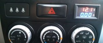
Indicators
Dashboard
At the moment of ignition, all the lights on the instrument panel light up; after the engine starts, most of the indicators go out. Sometimes, even after starting the engine, one light continues to glow or even blink. This alarms drivers, because it is difficult to say which component in a VAZ 2110 car is malfunctioning; diagnostics are required to determine the breakdown.
We know that the “ten” can be old or new. In both versions, the designations remain identical, the only difference is the location of the light bulbs and their diagram.
At the bottom of the instrument panel there are indicators that indicate a malfunction in the operation of various systems of the VAZ 2110. If they continue to light when the engine is running, it means that repairs will have to be carried out.
We go from left to right:
- The leftmost light, located on the instrument panel, refers to the air damper - the indicator is present in models with a carburetor engine;
- Oil can icon. If the indicator lights up or flashes, it means that the oil compression in the power unit has dropped and the pump is not working properly;
- The letter "P" inside a circle. The dashboard tells you that you forgot to turn off the parking brake;
- A light indicating a faulty battery or generator. Perhaps the alternator belt has broken, there is an open circuit in the circuit, charging is not performed;
- When the “high beam” is working, the headlight icon lights up on the panel;
- On light bulb icon – the indicator shows the lights on;
- "Check Engine" indicator. If it burns, then it is urgent to carry out diagnostics and subsequent repair of the VAZ 2110 engine; serious defects have appeared in the operation of the power plant. The best solution is to stop moving;
- Directly above the faulty engine sign is a warning light.
Engine control circuit VAZ-21102, 21103
Engine control circuit for VAZ-21102, VAZ-21103 (controller M1.5.4N, “January-5.1”).
1 - injectors 2 - spark plugs 3 - ignition module 4 - diagnostic block 5 - controller 6 - block connected to the instrument panel wiring harness 7 - main relay 8 - fuse connected to the main relay 9 - electric fan relay 10 - fuse connected to electric fan relay 11 – electric fuel pump relay 12 – fuse connected to the electric fuel pump relay 13 – mass air flow sensor 14 – throttle position sensor 15 – coolant temperature sensor 16 – idle speed regulator 17 – VAZ-21102 oxygen sensor 18 – knock sensor 19 – Crankshaft position sensor 20 – canister purge solenoid valve 21 – immobilizer control unit 22 – immobilizer status indicator 23 – vehicle speed sensor 24 – electric fuel pump with fuel level sensor 25 – oil pressure warning lamp sensor 26 – coolant temperature indicator sensor 27 – level sensor oil 28 - phase sensor (installed on a car with a 16-valve engine) A - block connected to the wiring harness of the anti-lock brake system (ABS) B - block connected to the air conditioner wiring harness C - block connected to the electric fan wiring harness D - wires , connected to the ignition switch (backlight lamp) E - block connected to the blue-white wires disconnected from the ignition switch (when installing the immobilizer) F - to the “+” terminal of the battery G1, G2 - grounding points The diagram uses the designation of the element number circuit to which this wire is connected, for example “-4-”. In some cases, in addition to the designation of the element number, it is given through an oblique fraction and the contact number, for example “-5/15-”. The diagram does not show the connection points of the pink-black, red and green with a red stripe wires.
Pinout of 8-pin connector
- power supply
- speed sensor (electric speedometer)
- fuel consumption (for BC)
- coolant sensor
- emergency oil pressure
- check lamp
- oil level sensor
- tachometer signal
Basic operating principle of electrical equipment
Note. It should be noted that the general principle of operation of electrical equipment on all VAZ families is identical.
- absolutely all electronic devices of the car are connected according to the principle of a single-wire circuit;
VAZ 2110 wiring diagram
- the car body acts as a negative wire;
- all consumer terminals, together with power sources, have a direct connection to the car body.
Note. All electrical wiring wires have a strictly defined color, which is indicated in the diagram by the first letter of the name of the corresponding word.
The power wire is always marked in red in all diagrams and is designated by the letter “P”, since it supplies power to the positive terminal of the battery.
Electrical circuit of ECM VAZ-21104
1 – block of the ignition coil wiring harness to the ignition system harness; 2 – block of the ignition system harness to the ignition coil wiring harness; 3 – ignition coils VAZ-21104; 4 – immobilizer warning sensor; 5 – immobilizer control unit; 6 – spark plugs; 7 – nozzles; 8 – diagnostic block; 9 – block of the ignition system harness to the ABS cabin group harness; 10 – controller; 11 – electric fuel pump; 12 – block of the ignition system harness to the fuel level sensor harness; 13 – fuel level sensor harness connector to the ignition system harness; 14 – block of the ignition system harness to the injector harness; 15 – injector harness block to the ignition system harness; 16 – block of the ignition system harness to the side door harness; 17 – speed sensor; 18 – idle speed regulator; 19 – throttle position sensor; 20 – coolant temperature sensor; 21 – mass air flow sensor; 22 – oil pressure warning lamp sensor; 23 – phase sensor; 24 – oxygen sensor; 25 – crankshaft position sensor; 26 – knock sensor; 27 – solenoid valve for purge of the adsorber; 28 – oil level sensor; 29 – coolant temperature indicator sensor; 30 – block of the ignition system harness to the instrument panel harness; 31 – instrument panel harness connector to the ignition system harness; 32 – ignition relay; 33 – ignition relay fuse; 34 – fuse for the electric fuel pump power supply circuit; 35 – electric fuel pump relay; 36 – electric fan relay; 37 – controller power supply fuse; 38 – ignition system harness block to the air conditioner connector; 39 – instrument cluster; 40 – ignition switch; 41 – electric fan of the cooling system; 42 – on-board control system unit; 43 – starter relay; 44 – contacts of the 8-terminal blocks of the instrument panel harness and the front harness; 45 – contacts of the 21-terminal blocks of the instrument panel harness and the rear harness; 46 – trip computer; 47 – diagnostic connector.
- A – to the “plus” terminal of the battery;
- B1 – grounding point of the ignition coil wiring harness;
- B2 – grounding point of the fuel level sensor harness;
- B3, B4 – grounding points of the ignition system harness;
- C – to the starter;
- D – to the driver’s door interior lamp switch.
According to the scheme described above, fuel regulation in a car is carried out. Moreover, it depends not only on the load of the valves in the engine, but also on the corresponding position relative to the throttle valve. With the help of a diagram of electrical wiring and valves, it is possible to understand which of the relays or fuses is malfunctioning and replace it in time. In this case, one of the main roles when supplying fuel is played by electrical equipment (controllers) that regulates the operation of the injector.
Recommendations
Comments 26
It’s not easier to open Google and write this question there. You'll do it much faster
Murzilka to help on the Internet there are a lot of wiring diagrams, take from 113-115 the diagram there is a pinout where and where
It can’t be any other way.
I connected 3 AA batteries, attached wires to the poles and looked for where + where -. and if you are going to install diodes instead of light bulbs, then to find + and - on the diode you will need current
the test will work too
also an option, but I simply don’t have it)))
I connected 3 AA batteries, attached wires to the poles and looked for where + where -. and if you are going to install diodes instead of light bulbs, then to find + and - on the diode you will need current
Direction indicators
The direction indicators (left or right) are activated by the steering column switch.
The hazard warning mode (all direction indicators flash) is activated by pressing the corresponding button. The blinking of lamps in this mode is ensured by a relay-breaker K3 type 493.3747 in the mounting block.
If one of the turn signal lamps burns out, the blinking frequency of the remaining lamps and the warning lamp doubles. In normal mode, the blinking frequency should be 90±30 cycles per minute at an ambient temperature of –40 to +65°C and a voltage of 10.8 to 15 V.
Diagram for switching on direction indicators and hazard warning lights
1 — direction indicator lamps in the headlights 2 — mounting block 3 — ignition switch 4 — hazard warning switch 5 — side direction indicators
6 — turn signal lamps in the outer rear lights 7 — turn signal switch 8 — instrument cluster with turn signal and hazard warning lamps K3 — relay-breaker for turn signals and hazard warning lights A — to power supplies
Removing the parking light, fog light and turn signal