Hello my readers, thanks for stopping by! Enjoy reading! And so today I want to tell you, describe how the size indicator was made not deactivated. Having made the automatic on 2110 (there will be a report on this too), I stopped paying attention to the low beams being on, because there are fog lights in the role of DRLs. But sometimes, coming in the evening, in the twilight the dimensions remained clear. At dusk, when you are in a hurry, you don’t really look at the light. Staying with the lights on at night kills the battery. On the recording I found an article where the guys tied BSK to size. I decided to repeat it. I found a diode, soldered the wires and went to install it in the car.
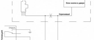
The essence of the installation: BSK gives audible and intermittent beeps when the dimensions are not turned off. Nuances: BSK does not beep when the dimensions are active: when starting the car, when inserting the key into the ignition. But as soon as you turn off the car, take out the key, you'll hear size warning signs. Production: For those who are forgetful, and most importantly hasty and careless, this is a very useful review. Connection diagram: found here on DRIVE2 (I’ll post a photo if the author sees it - signature, thanks for the tip)
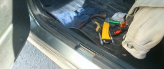
Installation process: I took out the BSK, watch 2110. I started looking for the wires from the cigarette lighter. Ambush: You can't get there. I moved them to the side, under the tunnel. I looked at the BSC and my watch. But the watch still has a backlight from its dimensions and there is no need to delve into tunnels. I connected it according to this diagram and secured it with electrical tape. I didn’t cut anything out, I stuck it into the watch blocks and the BSK.
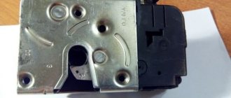
Tested: It works, hooray! In case anyone needs the pinout of the connectors on the 2110 watch: four wires fit to the clock block (VAZ-2110): - white (size), - black ("ground"), - orange (constant power), - white with a red stripe ("power" ")
The first VAZ 2110 cars were produced with a conventional eight-valve carburetor engine.
Which wires go where on the VAZ 2110 instrument panel pinout
Let's be honest - the VAZ 2110 does not have the most beautiful “native” instrument panel, neither on the first cars nor on the “improved” ones.
Therefore, many owners of this model are trying to make it more modern and somehow decorate it (with LEDs, beautiful lights, etc.). But, before you decide on some kind of upgrade, it is necessary that you have before your eyes the pinout of the instrument panel for the VAZ 2110, otherwise you can simply get lost in a heap of wires, sensors and buttons. Moreover, it will be useful regardless of whether you completely change the panel, or simply make some additions to the dashboard of your VAZ 2110.
How to find limit switches quickly and without any problems
Many people do not quite know where the limit switches are located in Kalina, Niva or other cars. But when you have to install an alarm, searching for them takes quite a lot of time. In order not to waste extra time on inspecting the interior of your own car, you should use the following tips:
- find the documentation for the car and look at the layout of various systems, devices, limit switches and wires that lead to them;
- look at the instructions for the alarm system - often this is where you can find the location of connection points such as limit switches;
- look for a layout diagram for a Niva, Viburnum or other vehicle models on the Internet;
- look for these points in the car interior using a voltmeter.
These methods will help the car enthusiast find absolutely all limit switches if he needs to connect an alarm system or replace these switches with new devices. The limit switches are designed to make it easier for the driver to deal with different systems of the car, and it doesn’t matter whether it’s a domestic car - Niva, Kalina or foreign models, everything will be as comfortable as possible.
Connection knowledge
Before starting dismantling work, you need at least a conventional pinout on paper, otherwise it will be very difficult: you will need to “trace” every wire and every connection that is on the “path” from the devices to the power button.
In fact, the pinout of the VAZ 2110 dashboard is not so difficult to understand, but there are differences between cars produced in different years and at different factories. There is an old model, there is one with a mechanical odometer, and a new (Euro) model, so there are differences in the pinout of the instrument panel, depending on the type to which it belongs.
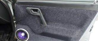
VAZ 2114 door switch wire
Limit switches - also known as limit switches - are electromechanical devices whose task is to open/close an electrical circuit.
Although the device was originally developed for use in engineering structures, but with the increase in the number of electronics in vehicles, they began to be widely used in their control system. So, since the 50s of the last century, almost all cars were equipped with an automatic system for turning on the light in the cabin when the front door was opened, but with the progress of progress, an increasing number of tasks began to be assigned to the limit switches used in the car, for example, the limit switches of the VAZ 2114 are located on the entrance doors and trunk.
General diagram of devices
If you look from the back of the instrument panel, here it is in sequence - from top to left to right:
- Fuel level indicator;
- Combination of instrument lighting lamps;
- Right turn control;
- Left turn control;
- Tachometer;
- Next is the block, there are a lot of plugs in it;
- And the top part of the dashboard is completed by an antifreeze temperature indicator.
VAZ 2110 dashboard connection diagram
The lower part of the dashboard (also from left to right and from the back of the dashboard). The following part of the instruments is located here:
- high beam controller (bulb);
- alarm controller;
- brake fluid level control lamp;
- speedometer;
- CHECK ENGINE controller;
- battery charge control;
- parking brake controller;
- oil pressure controller;
- air damper controller in the carburetor;
- outdoor lighting controller.
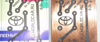
White block
The connector number, wire color and the unit (assembly) to which it goes are located in the white block as follows:
- The first connector has a black wire. Its purpose is the body (mass);
- In the second - red-brown - this is a low-voltage supply from the electronic control unit - tachometer;
- The third, yellow one is also a tachometer, but this is a high-voltage supply from a coil;
- The fourth, red-blue is Const from the battery + 12V, going through the sixth fuse;
- The fifth, green-white - it is intended to indicate the coolant temperature;
- Sixth, green-yellow – for size fuse F1;
- The seventh connector does not have its own color and goes to the “choke”, the throttle valve;
- Eighth, red and white - CHECK ENGINE light;
- In the ninth and tenth there are 2 orange wires each, leading to 2 power fuses F19+12V;
- In the eleventh there are 2 blue-brown wires leading to the “BK” terminal of the parking brake;
- The twelfth, brown-white is the output “D” of the generator;
- Thirteenth, gray and blue – for the oil pressure sensor.
White block (X1) and Red block (X2) of the VAZ 2110 instrument panel
Red block
The number is the connector according to the account, followed by the color of the wire and an indication of the device to which it goes in the red block of the VAZ 2110:
- Blue and red go to the sensor showing the external temperature;
- Orange - power fuse F19+12V;
- Black, 2 wires – ground, body;
- White - light switch for all devices;
- Blue - right direction indicator;
- Blue and black - left turn signal;
- Blue with pink - TJ level;
- Brown – leading to the trip computer;
- Gray - speed indicator;
- Pink - Fuel gauge (terminal “T”);
- 2 black-green wires - high beam fuse (F3);
- Blue and white - emergency light switch;
- White - leading to the ignition switch (terminal 50).
Nuances of work
However, these pinout diagrams for the VAZ 2110 are, so to speak, basic, mostly the same, but there are also differences in color markings (especially by manufacturer). Therefore, you need to either use the instruction manual that came specifically with your car, or, armed with a marker and self-adhesive labels, “write everything out” in detail and not get confused when installing a new instrument panel.
Connecting wires to the VDO panel on a VAZ 2110
Connecting wires to the “Schetmash” panel in Kursk on a VAZ 2110
Connecting wires to the “AP” panel in Vladimir on a VAZ 2110
Connecting wires to the panel from the Kalina car to the VAZ 2110
During subsequent assembly, there will probably be a lot of devices that are not taken into account here, and, taking into account modern realities, many car owners plan to install them on the updated dashboard.
Troubleshooting door switches
The fault in this case lies only with the owner of the car, who, due to inattention, was unable to notice the non-working door switches in time. After all, monitoring their operation in each machine is very clear and it is difficult not to notice a non-working condition.
But the solution to this problem today is quite simple - a sealed boot that completely covers the button and does not allow dust, dirt and moisture into this mechanism.
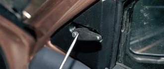
Before you start installing the boot, you need to pierce a cross-shaped notch on its underside where the end switch is attached. After this, you need to install a self-tapping screw in the button hole, then put on the boot and insert a screwdriver through the puncture and secure it to the body. This method surprises with its reliability, simplicity and accessibility.
Connecting the trip computer
The mentioned diagram took into account only one, brown wire leading from the red block to the trip computer, but this is clearly not enough. Therefore, let's see how the pinout occurs here.
- The fuel consumption signal from the electronic control unit is indicated by a green wire;
- Orange leads to terminal “15” in the ignition switch;
- Red and white - to terminal “30” in the ignition switch;
- Black, which is common, goes to ground;
- The speed indicator corresponds to brown;
- The positive terminal of the fuel sensor is green and red;
- Responsible for lighting the dashboard white, it leads to the light control.
Make sure that the board is not damaged, on which, in fact, uninterrupted reading of information from your VAZ 2110 depends, and providing it to you through all those sensors and devices that you always see in front of you.
VAZ dashboard pinout
When repairing or replacing the dashboard (instrument panel) of VAZ cars with a more convenient and modern version of VDO, made with LEDs, you will need connection diagrams and pinouts of panel connectors. For this purpose, the editors of 2SHEMI.RU have prepared a complete collection of panel contact pinouts for all popular models of this car.
The main symbols that are found on the dashboard of absolutely any car of the VAZ family are: speedometer, fuel gauge, tachometer and sensors to indicate engine temperature.
Starter connection diagram for VAZ 21110
1 - battery; 2 - generator; 3 - snack; 4 - ignition switch
Write a reply Cancel reply
This site uses Akismet to reduce spam. Find out how your comment data is processed.
Buy this site
The standard clock, which is located on the dashboard of VAZ 2110 - 2112 cars, has a fairly simple design, but still this part often fails and has to be replaced. Many owners quickly break the case out of the panel, break the watch itself, and in some cases manage to break parts of the panel. In this case, special care must be taken.
To remove the clock, or rather remove it from the dashboard, we will need two thin flat-blade screwdrivers, although everything can also be done with one:
You need to insert screwdrivers on the sides of the case and, as it were, lift the watch or from above, as shown in the photo:
Then pull them out of the recess slightly to gain access to the power cables and light bulb.
If you need to replace your watch, unplug it from the socket and simply insert a new one in its place. If you just need to change a light bulb because it's burned out, carefully twist the cap:
And then you can remove the light bulb by also turning it counterclockwise from the base:
We installed a new light bulb and now the backlight should work smoothly. Let's put the clock back in reverse order. The price of new VAZ 2110-2112 is about 450 rubles.
Pinout of the dashboard of VAZ2105, 2106, 2107
Old panel (with oil pressure gauge)
In addition to the presence of an oil pressure indicator, it is worth noting that this instrument panel does not have an air damper indicator lamp (choke), and the emergency oil pressure lamp is located next to the pressure indicator. Because of this, it contains lamps for low brake fluid levels and fog lamps.
White 6-terminal block X1:
- Gasoline level sensor
- Turn signal indicator lamp
- Battery charge sensor (voltmeter -)
- Gasoline level warning lamp
- Overall plus (+)
- Battery charge sensor (voltmeter +)
White 8 terminal block X2:
- Fog lamp warning lamp
- High beam warning lamp
- Dimensions indicator lamp
- Empty
- Battery charge indicator lamp
- Brake fluid level warning lamp
- Empty
- Parking brake warning lamp
Orange 6-terminal block X3:
- General minus (-)
- Tachometer VAZ
- Instrument lighting
- Oil pressure sensor
- Oil pressure warning lamp
- Coolant temperature sensor
New instrument panel (with econometer)
Here, everything is the other way around - there is no oil pressure indicator (instead there is an econometer), instead of a brake fluid level lamp there is a suction lamp (or an engine management system lamp on injectors), and instead of a fog lamp lamp there is an oil pressure lamp.
White 6-terminal block X1:
- Gasoline level sensor
- Turn signal indicator lamp
- Battery charge sensor (voltmeter -)
- Gasoline level warning lamp
- Overall plus (+)
- Battery charge sensor (voltmeter +)
White 8 terminal block X2:
- Dimensions indicator lamp
- High beam warning lamp
- Oil pressure warning lamp
- Empty, but there is a terminal in the wiring that goes to the brake fluid level sensor
- Battery charge indicator lamp
- Indicator lamp for the air damper (choke) or engine control unit for injectors
- Empty
- Parking brake warning lamp (handbrake)
Orange 6-terminal block X3:
- General minus (-)
- Tachometer (if this contact is empty, then the tachometer is on pin #4)
- Instrument lighting
- Empty, and if not empty - to the tachometer
- Empty
- Coolant temperature sensor
Second connection diagram option
Pinout of the dashboard VAZ2108, 2109, 21099
Connection diagram of the instrument cluster before 1996.
1 – relay-interrupter for the parking brake warning lamp; 2 – tachometer with voltage stabilizer; 3 – instrument cluster lighting lamp; 4 – temperature indicator; 5 – BSK control unit; 6 – fuel level indicator; 7 – resistor 50 Ohm, 5 W; 8 – control lamp “CHECK ENGINE” for the toxicity reduction system; 9 – control lamp for high beam headlights; 10 – side light indicator lamp; 11 – backup warning lamp; 12 – warning lamp for unfastened seat belts; 13 – control lamp for left direction indicators; 14 – resistor 470 Ohm, 0.25 W; 15 – electronic voltmeter; 16 – control lamp for right direction indicators; 17 – warning lamp for emergency oil pressure; 18 – fuel reserve warning lamp; 19 – control lamp for the carburetor air damper; 20 – indicator lamp “CHECK ENGINE” for the fuel injection system; 21 – parking brake warning lamp.
Instrument cluster wiring diagram after 1996
1 – tachometer; 2 – instrument cluster lighting lamp; 3 – temperature indicator; 4 – BSK control unit; 5 – fuel level indicator; 6 – control lamp “CHECK ENGINE” for the toxicity reduction system; 7 – control lamp for high beam headlights; 8 – side light indicator lamp; 9 – backup warning lamp; 10 – warning lamp for unfastened seat belts; 11 – control lamp for left direction indicators; 12 – battery charge indicator lamp; 13 – control lamp for right direction indicators; 14 – warning lamp for emergency oil pressure; 15 – fuel reserve warning lamp; 16 – control lamp for the carburetor air damper; 17 – indicator lamp “CHECK ENGINE” for the fuel injection system; 18 – parking brake warning lamp; B1 – resistor 91 kOhm; B2 – resistor 50 Ohm, 5 W.
Pinout of the dashboard of VAZ2110, 2111, 2112
- fuel reserve warning lamp;
- dashboard lighting lamps;
- right repeater indicator lamp;
- left repeater indicator lamp;
- VAZ plug block;
- coolant temperature sensor;
- indicator lamp for external lighting;
- carburetor air damper warning lamp;
- oil pressure warning lamp;
- handbrake indicator lamp;
- battery charge indicator lamp;
- VAZ tachometer;
- indicator light “CHECK ENGINE”;
- speedometer dashboard;
- brake fluid level warning lamp;
- hazard warning lamp;
- high beam indicator lamp;
- fuel level indicator.
| White block (X1) | Red block (X2) | ||
| 1 | Housing (weight) | 1 | To terminal “W” of the fuel level indicator sensor |
| 2 | Tachometer (low voltage input from ECU) | 2 | Fuse F19 + 12V power supply |
| 3 | Tachometer (high voltage input from coil) | 3 | Housing (weight) |
| 4 | Const +12V from battery (via 6th fuse) | 4 | Instrument lighting switch |
| 5 | Coolant temperature sensor. | 5 | Turn signal RIGHT |
| 6 | Fuse F1 (side light) | 6 | Turn signal LEFT |
| 7 | Throttle valve (“choke”) | 7 | Brake fluid level |
| 8 | Check Engine Light | 8 | To the trip computer |
| 9 | Fuse F19 + 12V power supply | 9 | Speed sensor |
| 10 | Fuse F19 + 12V power supply | 10 | Terminal “T” fuel gauge |
| 11 | Parking brake, terminal “VK” | 11 | Fuse F3 (high beam) |
| 12 | Generator output “D” | 12 | Hazard switch |
| 13 | Oil pressure sensor | 13 | To terminal “50” of the ignition switch |
Instrument panels VAZ VDO (LED)
You can install a more beautiful and convenient panel with LED indicators, the so-called VDO panel. Here VDO is the panel manufacturer.
| Connecting VDO on a Kalina car | ||
| 1 | Pink-white | To electric power steering |
| 2 | Blue and white | To the hazard warning indicator |
| 3 | Gray-blue | To emergency oil pressure sensor |
| 4 | Brown blue | To the parking brake switch |
| 5 | Yellow-blue | To the immobilizer control unit |
| 6 | Black | To the airbag control unit |
| 7 | Yellow | To the outside light switch |
| 8 | Blue | To the right turn signal switch |
| 9 | Blue with black | To left turn signal switch |
| 10 | White-blue | TO ECU |
| 11 | . | To brake pad wear sensor |
| 12 | . | To seat belt sensor |
| 13 | Black | To the traction control control unit |
| 14 | Red-blue | “RESET” key on the steering column switch |
| 15 | Pink-blue | To brake fluid level sensor |
| 16 | Black | To ABS |
| 17 | Green | To the high beam switch |
| 18 | White | To the instrument cluster light control |
| 19 | Brown | Panel weight |
| 20 | White-red | Terminal “30” |
| 21 | Orange | Terminal “15” |
| 22 | Yellow-red | To fuel flow sensor |
| 23 | Orange-white | MK key “forward” |
| 24 | White black | MK key “back” |
| 25 | Black and white | Outside temperature sensor (-) |
| 26 | Yellow-green | Outside temperature sensor (+) |
| 27 | Pink | Fuel level sensor |
| 28 | Grey | Speed sensor |
| 29 | Green-white | Coolant temperature sensor |
| 30 | Brown-red | Tachometer (low voltage) |
| 31 | . | Official. Panel diagnostics. |
| 32 | Brown-white | Terminal “L” of the generator relay regulator |
VAZ 2110 - modifications
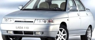
VAZ-21100 . The base model which was produced from 1996 to 2000. The car was equipped with an 8-valve carburetor VAZ-21083 engine with a displacement of 1.5 liters and a power of 69 horsepower.
VAZ-21101 . This modification has been produced since 2004, equipped with an 8-valve gasoline injection engine with a displacement of 1.6 liters.
VAZ-21102. Like the previous modification with an 8-valve injection engine, but with a volume of 1.5 liters.
VAZ-21103 . Modification of the “tens” with a 16-valve injection engine with a working volume of 1.5 liters.
VAZ-21103M . A restyled modification of the VAZ-21103, equipped with a 16-valve petrol injection engine with a displacement of 1.5 liters and a power of 92 horsepower. Produced since 2002.
VAZ-21104 . The modification is equipped with a 16-valve petrol injection engine with a working volume of 1.6 liters.
VAZ-21104M . A restyled modification of the VAZ-21104, equipped with a 16-valve petrol injection engine with a displacement of 1.6 liters. Produced since 2004.
VAZ-21106 GTI . The engine of the VAZ-21106 GTI is the most powerful and expensive modification that has been produced since 2000. The car was equipped with a 2-liter 16-valve Opel C20XE gasoline engine with a capacity of 150 horsepower. The car was fitted with a body kit with swollen arches, and the track was widened by 76 millimeters. It was equipped with R15 wheels with low-profile tires.
VAZ-21106 Coupe . Coupe VAZ-21106 in a coupe body. A distinctive feature of the car was the presence of only two doors, which were lengthened by 250 millimeters, while the body was shortened by 170 millimeters. The engine was installed the same as in the previous VAZ-21106 GTI model.
VAZ 21106 WTCC . A sports modification of the 106 model, it participated in the 2008 FIA WTCC international championship.
VAZ 21107 . Modification of a car for rally competitions. It was equipped with a welded safety cage and a different suspension design.
VAZ 21108 "Premier" . A modification with a body lengthened by 170 millimeters in the rear door area, which provided more convenient entry and exit of passengers. It was equipped with a 1.5-liter injection 16-valve engine.
VAZ 21109 “Consul” . 4-seater luxury limousine based on the VAZ-2110 car. In addition to the length of the body, the dimensions of the rear door were also increased, for more convenient entry and exit of passengers. Equipped with a 1.5 liter engine and R14 or R15 wheels. Overall dimensions: length – 4950 mm, width – 1700 mm, height – 1440 mm. Fuel consumption in the urban cycle is 9.5 liters per 100 kilometers.
VAZ 2110-91 . Modification of the VAZ-2110 with a 1308 cm3 rotary piston engine. The car could reach speeds of up to 240 km/h, and acceleration from 0 to 100 km/h took 6 seconds.
A car with a 16-valve injection engine in the “Gran Lux” configuration includes:
- Electric windows;
- Door locking;
- Trunk lock lock;
- Velvet seat upholstery;
- Immobilizer;
- Heated front seats;
- Ventilated 14-inch brake discs;
- Rear spoiler with additional brake light;
- Fog lights.
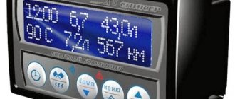
VAZ instrument panel indicators - explanation
- coolant temperature gauge.
- tachometer;
- left turn signal indicator lamp;
- right turn signal indicator lamp;
- speedometer;
- fuel level indicator;
- fuel reserve warning lamp;
- side light indicator lamp;
- service brake system warning lamp;
- high beam indicator lamp;
- reset button;
- mileage indicator;
- warning lamp for turning on the hazard warning lights;
- "check engine" warning light;
- time and temperature indicator;
- battery charge indicator lamp or battery lamp;
- parking brake warning lamp;
- oil pressure warning lamp;
- reserve.
VAZ dashboard indicators play an important role in informing the user about malfunctions. They help prevent errors in the system, so it is important to know which indicator means what. How does the panel work? If any problem occurs, the sensor immediately sends information to the panel, and the driver will see an orange signal light up.
The earlier version of the instrument panel had some other symbols, such as emergency oil pressure, handbrake engaged, Chek Engine light, and several others that indicate minor operating errors, but which are no longer used.
Improvement of the braking system
Many VAZ 2110 owners agree that the factory brake system is far from perfect. Therefore, they decide to modernize and improve the unit using technical tuning.
A popular solution to the issue of brake efficiency is to replace drum mechanisms with disc ones. Of course, in the case of the “ten” we are talking about the rear wheels. When replacing brakes, be sure to take into account the fact that the rear wheels must brake more softly and somewhat later than the front wheels. This way the car won't skid and you won't fly off the road.
Another option is to remove the factory brake master cylinder and vacuum booster. Instead, units from Priora are excellent. Such tuning will eliminate vibrations and also allow you to use the brake pedal effectively and without excessive effort.
Regardless of the changes made to the brake system, after each modification it is mandatory to pump the brakes.
Repair or replacement of the VAZ dashboard
If on a car on the instrument panel none of the indicators installed on it work (speedometer, odometer, tachometer, fuel level and coolant temperature indicators), then the first thing the driver will have to do is check the integrity of fuse F3, which is located in the mounting block . If it has burned out, then before replacing it, you need to find the reason why it burned out, otherwise the newly installed new fuse will have the same fate as the previous one. Most often, fuses burn as a result of a short circuit.
Even if the fuse is intact, then do not be lazy to take it out and check the condition of the contacts. There are cases when the contacts oxidize, and the electrical circuit in this place is interrupted. After making sure that the fuse is intact, the next step is to check the ignition relay, which is located inside the car to the left of the steering column. It is attached to a pin upside down. In the block where this relay is inserted, you can try to short-circuit the power wires using a jumper. If the instrument panel comes to life, the ignition relay will have to be replaced.
If the ignition relay is working properly, there are only two possible reasons for the instrument panel not working: the ignition switch and the mounting block. Before installation on the VAZ-2109 car, the ignition relay and lock contacts often burned out and had to be cleaned by disconnecting the contact group from the lock itself. After changes were made to the principle of supplying voltage to the ignition switch, its contacts began to burn very rarely, but the likelihood of this phenomenon still remained. On the mounting block, in its board, tracks may burn out; in order to see this, the mounting block will have to be removed from the car.
In addition to the reasons listed above, which can lead to failure of the instrument panel, it is also necessary to check the reliability of the fastening of the ground wire. Most common problems:
- burnout of incandescent lamps or failure of the LED group;
- oxidation of connectors;
- electrical wiring fault;
- failure of the fuse box;
- damage to the common contact board;
- no weight on the body (minus) or damage to the dimensions system.
To find a fault, you must use diagnostic equipment, a tester or a voltmeter. If a breakdown is found, you can begin repairs.
Connecting an alarm to the door limit switches of VAZ 2108, VAZ 2109, VAZ 21099, Lada Samara
In general, there are no special problems here.
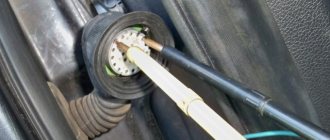
The chisel uses a negative polarity circuit. That is, when the door is opened, the limit switch closes the white-black wire to ground, and the presence of ground on this wire serves as a signal for the door to open. Most VAZ 2108 alarms have such an input, usually designated as a “negative door trigger”. However, if you have a chisel with an injection engine and an APS-4 immobilizer, simply connecting the warhead wire to the alarm input is not enough. That is, it’s enough, but you will have to arm the car or after the “polite illumination” of the interior lamp goes out (if you don’t wait, the alarm will think that the doors are not closed, and at the moment of smooth extinguishing v it will think that the doors are being opened /close), or enable the “arming delay” function in the alarm system (if there is one). But in my opinion, both of these options are unacceptable. Counting to 20 every time is stupid, and leaving the car unguarded for 30..60 seconds is simply dangerous; during this time you will have time to lose a lot of things in the cabin.
The reason for the problem is that VAZ designers have included a delay function for turning off the interior lighting in the anti-theft system (a controversial step, of course, but the giraffe is big). It works as follows (see the top diagram in Fig. 1).
The green-black wire from the 10th contact of APS-4 is connected to the white-black wire of the door limit switches. This contact on APS-4 is both an input and an output. When the door opens, the limit switch closes the warhead wire to ground, and with it the AF wire of APS-4 and APS-4 “sees” that the door is open and goes into key reading mode. When the ignition is turned off and the door is closed (APS-4 “sees” this by the loss of ground on its AF wire), APS-4 itself “provides” mass to the AF and, therefore, to the warhead wire of the door limit switches. That’s why the lamp continues to light, and the alarm connected to the warhead wire “thinks” that one of the doors is open: there is a mass on the warhead wire, though not from the limit switch, but from the APS-4! But the most interesting thing begins with the “smooth extinguishing” of the interior light. For smooth extinction, APS-4 emits mass pulses with decreasing duty cycle to the lampshade. And the alarm thinks that the doors are opening and closing! True, some alarms “filter” such impulses and do not respond to these “openings”, and after a smooth extinguishing of the interior, they simply arm the doors.
The green-black wire from the 10th contact of APS-4 is connected by an insert between the warhead wire of the driver's door limit switch and the limit switch itself.
The problem can be solved in several ways: from barbaric cutting of the APS-4 to replacing the insertion of an additional end switch exclusively for the APS-4. In my opinion, the simplest and most correct way is to decouple the APS-4 and the warhead wire with a diode. To do this, you need to disconnect the “inset” of the AF wire between the AF wire and the driver’s limit switch. Connect the warhead wire directly to the limit switch. Everything here is on chips, there is no need to solder anything. Then you need to stretch the AF wire to the lampshade (it will have to be extended). It is better to pull it along the left pillar of the front door. It is not necessary to remove the ceiling if you have the skill. Otherwise, unscrew the fastenings of the sun visors and ceiling handle on the driver's side, and carefully bend the ceiling. Carefully! A delicate ceiling can be “broken” and then there will be an ugly stripe at the break point. From the lamp's connector, remove the chip to which two warhead wires go and insert the chip with the AF wire from the APS-4 there. Solder a diode between this wire and the warhead (which was removed from the connector), as shown in the bottom diagram of Fig. 1.
All. Now the alarm system, being connected to the warhead wire (in any place), will not respond to the “polite lighting”, and the alarm system will immediately protect the doors. Yes, and, of course, when the doors are opened, the APS-4 will go into key reading mode.
Removing the car dashboard
- Using a Phillips screwdriver, remove the three screws that secure the center console;
- remove the cover, the protrusion located at the bottom, remove the protrusion from the bracket;
- Using a nozzle, unscrew the five screws located in the console on the right and remove the screen;
- Disconnect the terminal with the (-) sign from the battery. If there is a radio receiver, you need to remove it, remove the plug from the shield;
- Disconnect the wires coming from the cigarette lighter, remove the cartridge;
- Using a narrow screwdriver, remove the handle from the levers;
- pull the handle towards the heating and fan switch;
- unscrew the two screws above the panel and the two located under it using a screwdriver;
- unscrew the screw located behind the panel;
- Also unscrew the two self-tapping screws securing the cover;
- disconnect the harness and wire connectors. To avoid confusion when installing the panels, you should mark the order in which they are connected;
- unscrew the fastening bolts;
- unscrew the two self-tapping screws, those that secure the bottom bracket using an 8 key;
- unscrew the self-tapping screw securing the light guide and remove it;
- Also unscrew the screws securing the heating unit;
- remove lamp sockets;
- after removing the external parts, remove the decorative insert;
- unscrew all nuts with a 21 key;
- hydrocorrector, remove its lamp;
- Unscrew the screws that are attached to the cross member on the left.
- Finally, the panel itself is removed. The panel is assembled accordingly in the reverse order.
In general, the repair work is quite doable even with your own hands, but before starting dismantling work, you need at least a pinout mapped on paper, otherwise it will be difficult: you will need to “trace” every wire and every connection that is on the “path” from devices to the power button.
Source