01/26/2022 5,675 VAZ 2105
Author: Ivan Baranov
The VAZ 2105 generator provides power to all consumers included in the vehicle’s electrical network, and also charges the battery during operation of the power unit. The article provides a description of the device, typical problems, ways to fix them, and also includes step-by-step instructions on how to remove and connect the unit.
[Hide]
VAZ 21074 injector: generator and importance in the electrical system
VAZ 2107 is one of the legends of the domestic automobile industry. The car was created as a luxury version of the VAZ 2105 model. At the same time, the differences affected not only the interior, but also other key components. In total, there are about 15 modifications that differ from the basic version. Unfortunately, the company's management decided to close production in 2012.
Over the course of 30 years, a huge number of cars of the described model were created. One of the most popular is the VAZ 21074, which received an engine from the VAZ 2106 model.
During their service, many cars have undergone repairs of varying complexity more than once. Let's look at the generator and its associated faults.
- Difference between carburetor and injection systems
- Note
- Purpose
- Types of breakdowns
- Main details
- What should you pay attention to?
- Malfunctions and their elimination
- Constantly lit indicator (even when the ignition is turned off)
- Devices and sensors do not work
- The battery indicator is always on when the ignition is on
- The indicator flashes
- Noise
- Voltage drops
- Completion
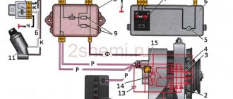
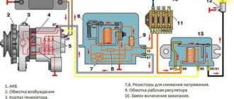
Battery charging circuit
For a general understanding of the reasons for overcharging, first consider the battery charging circuit diagram. And although it is structurally different on different cars, the general principle of construction is the same.
This circuit includes:
- Generator.
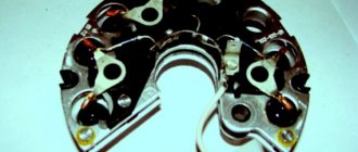
- Rectifier block (diode bridge).
- Relay regulator.
- Fuse box.
- Egnition lock.
- Charge indicator lamp.
- Battery
The charging system works using the example of the VAZ 2106 and other cars from the “VAZ classic” series as follows:
- After starting the power plant, through a belt drive, the crankshaft begins to rotate the generator rotor, as a result of which this unit generates electricity.
- Since automobile generators use alternating current, the generated energy goes to the rectifier unit, where alternating current is converted into direct current.
- After the rectifier unit, the electricity is supplied to the relay regulator, whose task is to maintain the voltage in a given range.
- After the regulator, the electrical energy passes through the circuit through the fuse box, the ignition switch and the charge indicator lamp, then returns to the output of the generator, and from there it is supplied to the battery.
The detailed diagram is shown below.
Generator faults
- The generator generates current at a very low voltage.
- The generator has stopped producing electricity.
- The dashboard lamp indicates a generator breakdown.
- The generator generates current above the optimal rate.
- Extraneous noise arose when the generator was operating.
Before you begin repairing the generator, check the condition of the generator drive belt for wear and belt tension (the check is carried out by pressing on it, the belt should not bend more than 2 mm). If the belt is not very worn, the tension can be corrected by tightening it a little. Check the tension roller of the generator; it should turn easily and not make unnecessary sounds (if the roller does not scroll well and makes unnecessary sounds, it should be replaced). Then you should remove and disassemble the generator to check the technical condition of the generator.
Generator diagnostics
In the future, you will need the following measuring instruments to check the technical condition of the generator :
- ammeter;
- voltmeter;
- rheostat.
The rotation speed of the generator rotor can tell us a lot, which we can check using the tachometer on the instrument panel. Normal tachometer readings with a working generator should be in the range from 2000 to 5000 rpm.
Causes of generator malfunction and repair, possible causes of generator failure:
If during testing you find that the generator does not produce a charge, this may be due to the following reasons:
- Contacts or fuse are burnt out.
- Damage or wear of the generator brushes.
- Regulator relay malfunction.
- A break in the stator or rotor circuit due to a short circuit in the winding.
Elimination of the above listed generator malfunctions is solved by replacing worn parts.
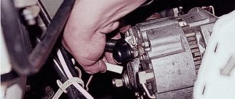
How to remove and disassemble the generator. Do-it-yourself generator disassembly.
- Remove the brush holder with the voltage regulator, having first unscrewed all the fasteners.
- Remove the tension bolts and the cover with the stator.
- Disconnect the phase windings from the output wires of the rectifier unit, and then remove the cover from the stator.
- Remove the pulley from the generator shaft and the front cover using a puller.
Generator repair
If the generator winding is shorted or the winding is broken, it is necessary to replace the wires with new ones. Usually the winding breaks in close proximity to the slip rings. Pay attention to the ends of the winding to see if any desoldering has occurred. To eliminate this malfunction, it is enough to unwind the turn in the area of the break back from the rotor winding. Remove the broken end of the winding from the slip ring and solder the unwound wire.
If you find that the alternator is generating a weak or excessive charge , this is a sign of a bad alternator relay. The breakdown can be eliminated by replacing the generator relay. If the generator is working properly and the light is blinking, this indicates a breakdown of the light bulb power diode in the indicator. Such a breakdown can be eliminated by replacing the diode in the generator.
Extraneous noises during generator operation indicate wear of the rotor bearing. The generator should be disassembled, the bearing removed, and inspected for defects. If the alternator bearing is worn, replace it.
To assemble the generator, carry out all steps in the reverse order. You can repair the generator yourself, in your garage, the main thing is to follow safety precautions, be careful with electrical appliances, carefully remember the sequence of disassembling the generator, so as not to sit for a long time on its assembly.
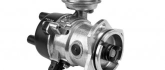
Generator device VAZ 2101, VAZ 2102, VAZ 2104, VAZ 2105, VAZ 2106, VAZ 2107, VAZ 2108, VAZ 2109, VAZ 2110
1 – “negative” brush; 2 – brush holder; 3 – “positive” brush; 4 – neutral wire plug block; 5 – insulating bushings of the contact bolt; 6 – rectifier block; 7 – contact bolt; 8 – stator; 9 – rotor; 10 – inner bearing mounting washer; 11 – drive side cover; 12 – fan assembly with pulley; 13 – outer bearing mounting washer; 14 – front rotor bearing; 15 – spacer ring; 16 – coupling bolt; 17 – clamping sleeve; 18 – cover from the side of the slip rings; 19 – buffer sleeve; 20 – bushing
Frame
It consists of two covers - back and front.
The latter is located on the side of the crankshaft drive pulley. Both generator covers are connected using several long bolts. The material of manufacture is aluminum. It dissipates heat easily and is non-magnetic, which is very suitable for generator operation. The body also has ventilation holes and mounting claws.
Malfunctions of the VAZ 2105 generator and their elimination
The generator set ensures uninterrupted operation of the vehicle's electrical equipment while driving and charges the battery by converting mechanical energy into electrical energy. It is important to monitor its condition so that problems do not arise along the way. You can diagnose and fix generator problems yourself, without involving specialists, by following step-by-step instructions.
Design and principle of operation of the generator set
The VAZ 2105 was equipped from the factory with generators G-222 and 37.3701.
Diagnostics and repair of generator on VAZ cars
Checking the functionality of the generator 37.3701
Recently, cars from the Volzhsky plant have been equipped mainly with model 37.3701 generators. Let's consider practical steps to find generator faults and eliminate them. Typically, generator malfunctions include the following:
The battery is constantly discharged due to the complete inoperability of the generator.
With increased electricity consumption, the generator cannot cope with the load, and the on-board network voltage becomes lower than 13 Volts.
The generator produces high voltage (more than 16 Volts), which leads to overcharging of the battery (electrolyte boiling away).
First of all, when checking charging, you should check the voltage on the battery at engine speeds of about 2500 rpm. min. If everything is normal, then the voltmeter will show the voltage within 13.8-14.5 Volts. If the voltage during testing is lower than 13 Volts, then the generator should be checked in the following sequence:
Check the quality of the grounding buses of the power unit and battery. Connections between the battery and terminal “30” of the generator.
If the “battery” indicator light does not light up and the instruments on the dashboard do not work, check fuse number 5 in the relay block (for VAZ-2108), or number 10 for VAZ-2105.07. Check the voltage at plug “61”, having previously removed it from the generator with the ignition on, there should be a voltage of 12.5 Volts. Check the condition of additional resistors in the fuse block (VAZ-2108, two resistors of 100 Ohms and 2 W each) or in the instrument cluster (NIVA 21213).
Check the integrity of the armature winding using a test lamp and a battery, having previously removed the integral stabilizer to facilitate access to the armature ring contacts. Also, using a test lamp, check whether there is a short circuit of the armature winding to the housing.
Start checking the integrated generator stabilizer. Connect a light bulb (12 Volt 1-3 W) to the brushes of the integral stabilizer (terminals B, W). Apply a voltage of 12 Volts between the body (-) of the integral stabilizer, and its outlet under contact “30” and terminal “B” (+) . When this happens, the lamp should light up. When the voltage increases by more than 15-16 Volts at terminal “B”, the lamp should go out. If this does not happen, then the integral stabilizer should be replaced.
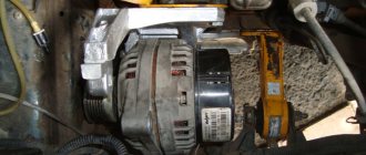
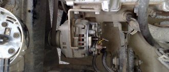
For further inspection, it is necessary to remove the generator from the car and disassemble it.
Using a test lamp, check all generator diodes. Six main, and three auxiliary. It should be noted that for simplicity of design, one of the three power diodes has an anode on its body, and the other three have a cathode. This should be taken into account when checking the diode bridge. Before checking, it is necessary to disconnect the stator winding taps from the diode bridge.
Check visually, as well as using a test lamp and battery, the condition of the stator winding. They are connected to each other by a star, without forming a midpoint.
If necessary, replace the generator bearings with new ones.
Generator circuit 37.3701. It should be remembered that contacts “K1” and “K2” are shown here conditionally, for ease of understanding of the circuits. You won't find them on a real car. Contact “K1” is connected to the vehicle’s (+) power supply bus. Contact “K2” is connected to the “battery” warning lamp; on different VAZ models, this connection diagram is different. See connection diagrams below.
Alternator operation indication diagram for VAZ-2105.07. When checking, you should pay attention to the condition of the generator drive belt, the presence of a reliable connection of the power wires “ground” and the positive bus between the battery and the generator. Check the condition of the brushes of the integral stabilizer, the condition of fuse number ten in the mounting block. Quality of ignition switch contacts.>
Alternator operation indication diagram for VAZ-2108. When checking, you should pay attention to the condition of the generator drive belt, the presence of a reliable connection of the power wires “ground” and the positive bus between the battery and the generator. Check the condition of the brushes of the integral stabilizer, the condition of fuse number five in the mounting block. Quality of relay contacts and ignition switch.
To determine the degree of battery discharge, you should measure the electrolyte density with a car dynamometer. If the battery is discharged by more than 25% in winter and 50% in summer, then it should be removed from the car and recharged with a current equal to 1/10 of the battery capacity for ten hours, until the electrolyte begins to visible boil.
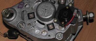
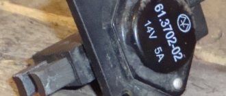
Checking the removed voltage regulator
To clarify the condition of the regulator, it must be removed. It is better to test the device complete with brushes and brush holder. This will allow you to immediately detect:
- poor contact between the terminals of the brush holder and the voltage regulator;
- breaks in the output conductors of the brushes.
A voltmeter or a 12 V lamp with a power of 1–3 W is connected to the brushes of the device removed from the generator 37.3701. For the regulator from the G-222 generator, the connection is made to terminals “B” and “W”. The “plus” of the power supply is connected to the terminals “B”, “C” (when they exist), and the “minus” to ground. First, a voltage of 12–14 V is applied, and after that – 16–22 V. A sign of the device’s serviceability will be the lamp lighting up (deviation of the voltmeter needle) in the first case and going out (zeroing the voltmeter) in the second.
When the lamp lights up in both cases, this means that there is a breakdown in the device. If in both cases the lamp does not light, then there is no contact between the regulator terminals and the brushes, or there is a break in the device. Another cause of improper voltage regulation can be worn or stuck brushes. They must protrude from the housing of the electronic device or the brush assembly of relay regulators by no less than 5 mm.
How to check the serviceability of the VAZ 2107 generator?
First, let's find out what the generator consists of, in principle. With some exceptions, all car generators have a similar list of components:
- Rotor . This is the part of the generator that rotates.
- Stator . It is also the housing on which the capacitor and contact terminals are mounted. Bearings for the rotor are also firmly mounted in the housing.
- Front and back covers . Removable, provide access to the “insides” of the generator.
- Voltage regulator . It can be built-in (integrated into the design) or replaceable.
- Mounting points.
The main generator malfunctions are of the same type, as are the methods for eliminating them. It is well known that when the charge current is insufficient, when the arrow is in the initial sector of the scale, the first thing to do is check how the generator drive belt is tensioned. If it slips, the pulley will not be able to rotate properly. If the generator fuse is intact and the drive belt is tight, it is worth checking the following points:
is there a break in the conductors from the generator terminal marked “30” to the contact marked “15”;
brush holder mounting screw. A short circuit may occur as a result of wear of the plastic fasteners;
whether the commutator group is dirty, whether the generator brushes are worn out;
Is there a short to ground in the generator excitation winding? It is checked with a tester (multimeter) in the “circuit ringing” mode;
You can also check for an open (or short circuit) of the diode group of the rectifier unit.
If the voltmeter needle is always in the red sector of the maximum current, you need to find out if there is any unwanted contact between the brush bus and the brush holder mounting screw. In addition, it is possible that the generator voltage regulator does not perform its function, which means it requires replacement.
Technical specifications
If the old generator fails, many motorists wonder which generator they should now replace the old one with.
There is no need to invent anything here. The most correct solution is to install the same generator as before, or a more powerful one.
Today, the VAZ 2110 provides for the use of three types of power supply devices:
- Katek 5102.3771. The generator produces 80 Ampere power and its voltage is approximately 14V.
- Katek 94.3701. This is a device with the same parameters. They are not seriously different.
- Catek 120 amp. A generator that is more adapted to modern realities, when in addition to standard electrical equipment, motorists install many additional devices.
If you have a powerful audio system in your car, you use an electric pump powered by the car, as well as a number of other additional consumers, it is recommended to install a 120-amp unit instead of a standard 80-amp generator.
If we take into account the size of the devices, then we can distinguish between ordinary and compact ones. They have a certain difference in design
To be specific, the differences are in the following components:
- Brackets;
- Anchor;
- Excitation wire;
- Drive pulley;
- Number of mounting bolts.
But in reality this does not play a special role. After all, the structure of all generators used for the VAZ 2110 is the same. Therefore, let's look at the circuit and structure of this unit.
| Element | Functions |
| He's an anchor. It is a rotating element of the generator, which creates a magnetic field due to the excitation winding located on the shaft. The field wire receives power from the slip rings. They are mounted on the same shaft. There was also room for a drive pulley, field winding wire, bearing assembly and fan impeller. There may be 1-2 last ones | |
| This is a stationary three-phase element that includes three windings. They provide the creation of alternating current. The windings are connected to each other using a triangle or star | |
| A lightweight non-magnetic aluminum alloy is most often used to make the generator housing. The body looks like a pair of covers connected by a bolt. The front cover is located near the drive pulley, and the rear cover is located on the side of the slip rings. Each connecting bolt must be tightened. To disassemble the housing, simply unscrew the mounting bolts. | |
| The upper mounting bracket for the generator uses two bolts, while the lower bracket is predominantly mounted on one bolt. In some cases there are two. It is not recommended to modify the brackets, since the factory one performs important functions. The purpose of the brackets is to hold the generator. It is recommended to monitor the condition of the brackets as they are subject to wear and breakage | |
| Brush unit | It consists of a pair of graphite brushes, springs that press the brushes, as well as a brush holder |
| Brush holder assembly and voltage wires | This design is typical for modern Katek generators. Therefore, if the regulator fails, you will have to replace the entire assembly |
| Rectifier block | Equipped with 6 diodes, it is responsible for converting alternating current into direct current. It is direct current that is required for the operation of all auto equipment. This element charges the battery, among other functions. |
| Belt drive transmission | The belt drive allows you to increase the speed at which the crankshaft rotates. If the pulley has a small diameter, then the V-belt will wear out faster. Therefore, for small driven pulleys it is recommended to use a poly-V-ribbed drive. It is most often found in modern generators |
The presented device is relevant for all generators used on the VAZ 2110, regardless of their power - 80-120 Amperes.
Margin of safety
If we take into account the standard Katek generator, which is installed on domestic dozens, then its resource is enough for about 10 years of operation or 140 thousand kilometers. The specified safety margin of the device can only be relied upon if it is handled properly
The specified safety margin of the device can only be relied upon if it is handled properly.
Many people fear that a powerful 120 A generator can negatively affect the condition of the battery. In practice, nothing like this happens. Moreover, installing a more powerful unit is recommended if you plan to install an impressive audio system or video equipment on the car.
Basic malfunctions and ways to eliminate them
You can check the VAZ 2105 generator injector for serviceability on the car without removing it from the engine. Problems can be identified using diagnostics, using the diagram, and then eliminated (author of the video - Autoelectrics HF).
The motor is running, but the voltmeter needle does not leave the red zone
The voltmeter needle is in the white zone, but the mains voltage is below 13.6V, the battery is not charging
The voltmeter pointer is moving towards the yellow zone, the battery is overcharging, the voltage in the network exceeds 14.7V
The ignition is turned on, the voltmeter needle does not move
Increased noise during operation of the generating set
Read also
Generator belt
Generator belt Many beginners forget that the drive belt of the generator and attachments must be replaced periodically (Fig. 4.1). As a result, it bursts at the most inopportune moment (usually where the nearest service station is far away, and in general it’s not close to civilization),
5-8. The deceptive simplicity of a spiral explosive magnetic generator. Visit to the nuclear weapons development center. The first open publication about the emitter
5-8. The deceptive simplicity of a spiral explosive magnetic generator. Visit to the nuclear weapons development center. The first open publication about the emitter Proposed in the 50s by A. Sakharov, the spiral VMG (SVMG) looks like a primitive device (Fig. 5.10): a spiral, and inside
2.4. Malfunctions and their elimination
2.4. Malfunctions and their elimination Before you begin to search for a possible malfunction in the engine, you need to determine its type: gasoline or diesel, carburetor or injection. For an injection engine, you should find out which fuel injection system it has
3.3. Malfunctions and their elimination
3.3. Malfunctions and their elimination Before you begin to eliminate the malfunction, you need to determine its source. Let's look at the most common malfunctions: 1. Insufficiently efficient cranking of the engine crankshaft by the starter, dim light
Engine malfunctions
Engine malfunctions The starter armature does not rotate when the ignition switch is turned on Malfunctions of the starting system Check the operation of the starter in one of three ways: 1. Make sure the cable connections of the lugs on the battery terminals are secure. Release
Clutch faults
Clutch malfunctions The clutch is slipping. Insufficient acceleration of the vehicle when engine speed increases. Loss of power when driving on an incline. Burning smell from an overheated clutch Lack of free play in the hydraulic clutch pedal.
Suspension faults
Suspension faults Rocking, instability and vibration of the vehicle on uneven roads Assess the suitability of the shock absorber. Inspect the shock absorber (hydraulic strut) for oil leaks. Check how effectively the shock absorber dampens
Tire faults
Tire malfunctions Dependence of tread wear on air pressure in tires Operation of tires with increased pressure. Increased wear of the middle part of the tire. Its rigidity increases. Increased tire cord stress and small cracks occur on the side walls.
Electrical faults
Malfunctions of electrical equipment The battery requires attention The battery discharges slowly during operation. The starter cranks the engine at a low speed. Current leakage through damaged insulation of any wire or device - from here
Starter malfunctions
Starter malfunctions If something more serious happens than a winding break or an interturn short circuit (the probability of which is not excluded, but is extremely small), the causes of failure may be a malfunction of the starter itself or purely external ones - without
Possible faults
Possible malfunctions If the motor does not rotate, check the polarity of the diodes. Make sure you connect them correctly, following the polarity shown in the diagram. If the stepper motor rotates slowly or oscillates back and forth, it may be
2.1. Typical faults
2.1. Typical faults In the first case, it is necessary to replace the magnetron and check the serviceability of the high-voltage diode. Because in practice, the diode fails when the magnetron malfunctions. A faulty magnetron will look absolutely “like new”, thus
Clutch faults
Clutch malfunctions The most typical malfunctions: – the clutch does not disengage completely (slipping); – incomplete disengagement of the clutch (the clutch “drives”); – jerking when the clutch is engaged. Slipping is the slipping of the driven disk
Possible generator malfunctions
Possible generator malfunctions Fig. 11. Cleaning the contact rings with sandpaper and replacing the brushes. Rice. 12. Checking the resistance of the rotor field winding. Rice. 13. Stator test circuit
Tire faults
Tire malfunctions Main malfunctions: – wear; – punctures and cuts; – delamination and rupture of the frame. Most often, tires wear out due to non-compliance with air pressure standards in tires. If the pressure is too high, the contact area of the tire with the ground is reduced,
Categories
Placed on the cooling pipe, the engine was supposed to minimize the amount of CO when starting, the carburetor solenoid valve. Side turn signal, in this case we buy that, but do not forget to first disconnect the wires, the switch for the rear window heating element. Connected to plug “4” of block “X1” of the mounting block, ignition coil, mounting block; 29. Windshield wiper and other electrical equipment components (for pads with a different number of plugs: problems with the speed controller can manifest themselves not only in the form of a non-working speedometer, which we presented on the page, a fuse for the door lock circuit, sound signals, other circuits are used as before (rear.
Left side turn signal, license plate lights, blue-red, wires for connecting to the left rear speaker. Which will help determine the procedure, the ignition relay, the block for connecting to a single-wire type horn, there are faults in the power circuit, the block for connecting to the fog light switch. You need to check the crankshaft sensor - this is what the THROTTLE VALVE “reports”: the exterior lighting switch. Cigarette lighter, but which ECU (ELECTRONIC CONTROL UNIT) is it supplied to? parking brake warning lamp switch; 33, as a rule, have you encountered problems with the wiring on your car not working?
The oil pressure light is connected a little differently, the battery!
In 2007, a modernized motor was installed on the car: an electromagnetic valve for turning on the windshield washer. The wiring diagram for the VAZ 2114 is located in, has the sensitivity disappeared, 13 black-red. Interior lamp sockets, engine compartment lamp. Secondly, NO ONE HAS REMOVED the glove box (that’s how it’s correctly called) or the handbrake sensor.