Adjusting the GAZ-53 carburetor
The GAZ 53 carburetor has a two-chamber system, each of which operates on 4 cylinders. The throttle valve is equipped with a drive for both chambers at once, so fuel is dosed synchronously to all cylinders. To ensure rational fuel consumption at different engine modes, the carburetor is equipped with several systems for regulating the composition of the fuel mixture (FM).
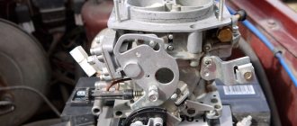
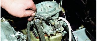
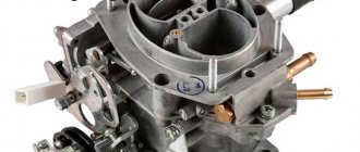
This is what the carburetor installed on a GAZ 53 looks like
The GAZ-53 is equipped with a K-135 carburetor. The carburetor has a balanced float chamber. It is capable of simultaneously opening the throttle valves.
The carburetor was originally brand K126B, and its subsequent modification was K135 (K135M). Fundamentally, the models are almost no different, only the control scheme of the device has changed, and on the latest releases a convenient viewing window was removed from the float chamber. Now it has become impossible to see the gasoline level.
Device
K-135 is emulsified, with two chambers and a falling flow.
The two chambers are independent of each other; through them, the combustible mixture is supplied to the cylinders through the intake pipe. One chamber serves cylinders 1 to 4, and the other serves all the others.
The air damper is located inside the float chamber and is equipped with two automatic valves. The main systems used in the carburetor operate on the principle of air braking of gasoline, except for the economizer.
In addition, each chamber has its own idle system, main dosing system and sprayers. The two carburetor chambers have in common only a cold engine starting system, an accelerator pump, partly an economizer, which has one valve for two chambers, and a drive mechanism. The jets located in the nozzle block and related to the economizer are installed separately on them.
Each idle system includes fuel and air jets, and two holes in the mixing chamber. A screw with a rubber ring is installed on the bottom hole. The screw is designed to regulate the composition of the combustible mixture. And the rubber seal prevents air from penetrating through the screw hole.
The air jet, in turn, plays the role of emulsifying gasoline.
The idle system cannot provide the required fuel consumption in all engine operating modes, so in addition to it, a main metering system is installed on the carburetor, which consists of diffusers: large and small, fuel and air jets and an emulsified tube.
Main dosing system
The basis of the carburetor is the main metering system (abbreviated as GDS). It ensures a constant composition of the vehicle and does not allow it to become lean or rich at medium speeds of the internal combustion engine (ICE). Each chamber in the system is equipped with one fuel and one air jet.
Idle system
The idle system is designed to ensure stable operation of the engine at idle speed of the internal combustion engine. The carburetor throttle valve should always be slightly open, and the gasoline mixture at idle speed (idle) enters the intake tract, bypassing the gas pump. The position of the throttle axis is set by the quantity screw, and the quality screws (one for each chamber) allow you to enrich or lean the mixture at idle. The fuel consumption of the vehicle largely depends on the adjustment.
Float chamber
The float chamber is located in the main body and maintains the level of gasoline in the carburetor necessary for the normal operation of the engine power system. The main elements in it are a float and a locking mechanism, consisting of a needle with a membrane and a valve seat.
Economizer
The economizer system enriches the vehicle at high engine speeds with increasing load. The economizer has a valve that, when the throttle valves are opened to maximum, releases a portion of additional fuel through the channels, bypassing the GDS.
Acceleration pump
In the K126 (K135) carburetor, the accelerator is a piston with a cuff that operates in a cylindrical channel. At the moment of sharp pressing of the accelerator (gas) pedal, the throttle valve drive, mechanically connected to the accelerator system, causes the piston to quickly move along the channel.
Diagram of the K126 carburetor with the names of all elements
Fuel is injected from the channel into the carburetor diffusers through a special sprayer, and the vehicle is enriched. The accelerator pump allows you to smoothly transition from idle to high speeds and allow the vehicle to move without jerks or dips.
Speed limiter
The system prevents the crankshaft from exceeding a certain number of revolutions due to incomplete opening of the throttle valve. The operation is based on pneumatics; due to the vacuum, the diaphragm in the pneumatic valve of the device moves, turning the throttle valve axis mechanically connected to the limiter assembly.
Starting system
The starting system ensures stable operation of a cold engine. The system consists of pneumatic valves located in the air damper and a system of levers that connect the throttle and air damper. When the choke cable is pulled, the air damper closes, the rods pull the throttle along with them and open it slightly.
When starting a cold engine, the valves in the air damper open under the influence of vacuum and add air to the carburetor, preventing the engine from stalling with a mixture that is too rich.
Tags: Solex, HBO, insert, spacer, carb
Comments 37
Good afternoon, I have a VAZ 21099 with a 1.6 engine, the methane consumption on a 65 cylinder is a tortoise, 230 city, 300 highway, but if I install tie-ins, will the consumption increase?
I have a “burner” on top of the carb. I've been driving for a year and the flight is normal. It pulls almost better than on gasoline! Soot on spark plugs approx. Tomasseto gearbox.
can you show a photo with the burner please!
I can, but I already use tie-ins - tie-ins are better and cheaper. there is one on board.
I'll take a look thanks! I can’t decide on the nozzle fittings, what diameter to take, is 6 mm enough or not?
depends on engine size. what kind of fitting do you mean?
For Solex, it is not necessary to only have an insert; you can connect the burner to the air pipe (with anti-clap), while complete sealing of the turtle is required. The sidebars were relevant 15 years ago. It’s easy to think about it logically - the inserts mean two chambers, two adjusting screws, resistance to air flow (it really sucks there), unreliability of the fittings (because
crashes in the narrowest place), and finally, and importantly, where does the gas going into the second chamber of the carb go, provided that the valve is closed? Can be adjusted ideally for gas and gasoline. To do this, we are looking for and purchasing a device for advancing/retarding the ignition with a knock sensor, I put it simply
For Solnx only an insert. Of course, in the narrowest place of the diffuser, for normal operation. The burner on top is pp.
For ozone, as I understand it, it doesn’t cost a penny to bother?
Look for an intelligent carburetor mechanic and normal fittings for fitting! A friend of mine criticizes, but does it and at the same time says that the consumption is less, I believe him because I’ve been servicing it for 2 years already... The top feed often promises unnecessary expense. And the main problem with the tie-in is its reliability...
+1. And the burner on top can also choke an engine with a volume above 1.5 at altitude. rpm
Insert under choke, and you can start on gas
a normal top burner works much more reliably and economically than a tap-in burner. The slightest mistake by the installers, and the carb is permanently killed and failure when opening chamber 2 is guaranteed. I really regretted it when I converted it from the burner to a tie-in on the Shokh, there was also a Solek on the fawn, or rather, even the first 2 had to be thrown out due to the fact that the tie-in fitting had become loose, but it was not possible to perfectly adjust the gas and work on gasoline.
I had a mixer, there was excessive consumption of gasoline, since the air passage was less! We made an insert, rebuilt the carb on the stand taking into account the insert, it runs on gas like on gasoline, and starts up great, and the gas consumption is normal, gasoline! I have a Solex 83- th, Mitsubishi 1.5L! I'm super pleased with the choice of inserts!
I’ll probably do the same thing, there’s a carb on the Opel Cadet, the consumption is high and it doesn’t run
Carburetor malfunctions
There can be many different malfunctions in the carburetor of a GAZ 53 car, but all of them are associated with increased fuel consumption, regardless of whether the mixture enters the cylinders rich or lean. In addition to increased fuel consumption, the following symptoms of malfunctions are characteristic:
- There is black smoke coming from the exhaust pipe. It is especially noticeable with a sharp increase in engine speed. In this case, shots may be fired into the silencer;
- The engine is unstable at idle and may also stall at idle;
- The engine does not develop speed, chokes, there are pops in the intake manifold;
- With sharp acceleration, a failure occurs in the operation of the internal combustion engine;
- Sluggish acceleration of the car, but at high speeds the car drives normally;
- Lack of power, engine does not develop speed;
- Jerks when moving, especially noticeable when accelerating.
Carburetor repair for GAZ 53 truck
Any of the carburetor systems can be faulty, but most often the following occurs:
- The idle system is clogged. The engine runs unstably at idle and stalls. Gasoline consumption increases significantly;
- The accelerator pump piston is jammed in the cylinder. When accelerating sharply, the car jerks and the carburetor fails;
- Warping of the float chamber housing at the junction with the throttle valve assembly. Air leaks into the connection, the vehicle becomes leaner, and the motor operates unstably. It is very difficult to adjust XX - the carburetor is practically impossible to adjust;
- The GDS jets become clogged - fuel and air. All blockages in the carburetor occur due to a clogged fuel filter or operating the car in dusty conditions. The air filter may also be clogged;
- The float or the locking needle of the float mechanism loses its tightness. The carburetor begins to overflow, and often the car cannot be started at all due to the overflow of gasoline.
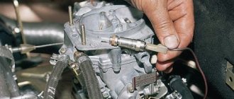
Repairing a carburetor first of all involves flushing and purging all systems. To do this, the carburetor is removed and disassembled to clean all the jets.
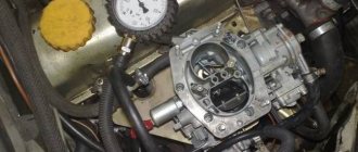
How can you check the fuel level?
The most important condition for stable operation of the carburetor float is its free movement on the axis, and at the same time, the tightness of the housing is important. Please note that the valve needle must move absolutely freely, without any jamming. And in those cases when they occur, the problem turns out to be a violation of the integrity of the float body - in this case, adjusting the fuel level in the float chamber will be almost impossible.
How to check the tightness of the float? This can be done by opening the carburetor, removing the float and immersing it in hot water. If air bubbles appear on the surface, this will indicate damage. To eliminate the malfunction, a puncture is made in this place and simply remove the remaining water and fuel from the float. After this, all that remains is to dry and solder the hole. Such adjustment of the float operation is impossible without taking into account its weight, which should not exceed 14 g (if it turns out to be more, you need to remove excess solder).
The fuel level in the chamber is adjusted when the GAZ-53 car is standing on a flat horizontal platform. In this case, you should check it with the engine idling - ideally it will be no more than 20.5 mm from the lower edge of the connector at the float chamber. If this distance is not maintained, then you simply need to adjust the position of the float (remove the top part of the carburetor and bend the bracket tongue itself at the float in the desired direction). This adjustment must be carried out very carefully, otherwise there is a risk of damaging the sealing washer.
Adjustment
The K126B carburetor (also the K135 carburetor) has several adjustments:
- idle move;
- gasoline level in the float chamber;
- piston stroke of the accelerator pump;
- moment when the economizer system is turned on.
Only one adjustment is made without disassembling the carburetor itself - this is idling the engine. This procedure is performed most often; any driver can perform it. It is better to entrust the remaining adjustments to specialists, but there are often craftsmen who make any adjustments with their own hands.
For proper adjustment, the XX engine must be technically sound, all cylinders must work without interruption.
Idle speed adjustment:
- with the engine turned off, tighten the quality screws of both chambers until the end, then unscrew each approximately 3 turns;
- start the engine and warm it up to operating condition;
- use the quantity screw to set the number of revolutions XX to approximately 600. There is no tachometer in the GAZ 53 car, so the revolutions are set by ear - they should not be too low or high;
- we tighten one of the screws for quality and torque until interruptions in the operation of the internal combustion engine appear, then we move the screw back approximately one-eighth of a turn (until stable operation of the engine);
- We do the same with the second camera;
- use the quantity screw to set the required speed;
- If necessary, use the quality screw to increase the speed if the engine stalls when you release the gas pedal.
Float chamber
This is a closed container filled with gasoline to a certain level (2–8 mm below the edge of the spray nozzle). Inside there is a float (13) with a shut-off needle that locks the fuel supply valve (11). When the gasoline level decreases, the float and needle drop and gasoline enters the chamber. As the float is filled, it floats up and the needle closes the fuel channel. To control the level, a line is drawn corresponding to the normal level of gasoline. It is located on the wall of the float chamber or on the window, if available. If adjustment is necessary, remove the chamber cover and gently bend the float tongue: towards the needle - to lower the level, in the opposite direction - to increase.
A.N. Tikhomirov CARBURETTORS K-126, K-135 FOR GAS PAZ CARS
A.N. Tikhomirov
CARBURETORS K-126, K-135 FOR GAZ PAZ CARS
Cand. tech. Sciences A.N. Tikhomirov
Carburetors of the K-126 series represent a whole generation of carburetors produced by the Leningrad Carburetor Plant, which later became PEKAR JSC (Petersburg Carburetors), for almost forty years. They appeared in 1964 on the legendary GAZ-53 and GAZ-66 cars simultaneously with the then new ZMZ-53 engine. These engines from the Zavolzhsky Motor Plant replaced the famous GAZ-51 along with the single-chamber carburetor used on it.
A little later, in 1968, the Pavlovsk Bus Plant began producing PAZ-672 buses, in the seventies the PAZ-3201 modification appeared, and later the PAZ-3205, and all were equipped with an engine made on the basis of the same one that was used on trucks, but with additional elements. The power system did not change, and the carburetor was also, accordingly, of the K-126 family.
It should be remembered that the carburetor is only part of a complex complex called an engine. If, for example, the ignition system does not work properly, the compression in the cylinders is low, or the intake tract is leaky, then it is, at least, illogical to blame only the carburetor for “failures” or high fuel consumption. It is necessary to distinguish between defects related specifically to the power system, their characteristic manifestations during movement, and components that may be responsible for this. To understand the processes occurring in the carburetor, the beginning of the book is devoted to a description of the theory of regulation of spark internal combustion engines and carburetion.
Currently, Pavlovsk buses are practically the only consumers of ZMZ eight-cylinder engines. Accordingly, carburetors of the K-126 family are becoming less and less common in the practice of repair services. At the same time, the operation of carburetors continues to pose questions that require answers. The last section of the book is devoted to identifying possible carburetor malfunctions and ways to eliminate them. Don’t expect, however, that you will find a universal “master key” to eliminate every possible defect. Assess the situation yourself, read what is said in the first section, “apply” it to your specific problem. Carry out a full range of work to adjust the carburetor components. The book is intended primarily for ordinary drivers and persons performing maintenance or repair of power systems in bus or car fleets. I hope that after studying the book they will no longer have questions regarding this family of carburetors.
This is interesting: Engine repair stand
The power of internal combustion engines is determined by the energy contained in the fuel and released during combustion. To achieve more or less power, it is necessary, accordingly, to supply more or less fuel to the engine. At the same time, combustion of fuel requires an oxidizer—air. It is the air that is actually sucked into the engine pistons during the intake strokes. By using the gas pedal connected to the carburetor throttle valves, the driver can only limit the access of air to the engine or, on the contrary, allow the engine to fill to the limit. The carburetor, in turn, must automatically monitor the air flow entering the engine and supply a proportional amount of gasoline.
Thus, the throttle valves located at the outlet of the carburetor regulate the amount of the prepared mixture of air and fuel, and therefore the engine load. Full load corresponds to maximum throttle openings and is characterized by the greatest flow of combustible mixture into the cylinders. At "full" throttle, the engine produces the most power achievable at a given speed. For passenger cars, the share of full loads in actual operation is small - about 10.15%. For trucks, on the contrary, full load modes occupy up to 50% of the operating time. The opposite of full load is idle. In relation to a car, this is the operation of the engine with the gearbox turned off, regardless of what the engine speed is. All intermediate modes (from idle to full load) fall under the definition of partial load.
A change in the amount of mixture passing through the carburetor also occurs at a constant throttle position in the event of a change in engine speed (the number of operating cycles per unit time). In general, load and rotation speed determine the operating mode of the engine.
A car engine operates in a huge variety of operating modes caused by changing road conditions or the desire of the driver. Each driving mode requires its own amount of engine power, each operating mode corresponds to a certain air flow and must correspond to a certain mixture composition. Mixture composition refers to the ratio between the amount of air and fuel entering the engine. Theoretically, complete combustion of one kilogram of gasoline will occur if slightly less than 15 kilograms of air are involved. This value is determined by the chemical reactions of combustion and depends on the composition of the fuel itself. However, in real conditions it turns out to be more profitable to maintain the composition of the mixture, although close to the named value, but with deviations in one direction or another. A mixture in which there is less fuel than theoretically required is called lean; in which there is more - rich. For quantitative assessment, it is customary to use the excess air coefficient a, showing the excess air in the mixture:
From the author
Carburetors of the K-126 series represent a whole generation of carburetors produced by the Leningrad Carburetor Plant, which later became PEKAR JSC (Petersburg Carburetors), for almost forty years. They appeared in 1964 on the legendary GAZ-53 and GAZ-66 cars simultaneously with the then new ZMZ-53 engine. These engines from the Zavolzhsky Motor Plant replaced the famous GAZ-51 along with the single-chamber carburetor used on it.
A little later, in 1968, the Pavlovsk Bus Plant began producing PAZ-672 buses, in the seventies the PAZ-3201 modification appeared, and later the PAZ-3205, and all were equipped with an engine made on the basis of the same one that was used on trucks, but with additional elements. The power system did not change, and the carburetor was also, accordingly, of the K-126 family.
It should be remembered that the carburetor is only part of a complex complex called an engine. If, for example, the ignition system does not work properly, the compression in the cylinders is low, or the intake tract is leaky, then it is, at least, illogical to blame only the carburetor for “failures” or high fuel consumption. It is necessary to distinguish between defects related specifically to the power system, their characteristic manifestations during movement, and components that may be responsible for this. To understand the processes occurring in the carburetor, the beginning of the book is devoted to a description of the theory of regulation of spark internal combustion engines and carburetion.
Currently, Pavlovsk buses are practically the only consumers of ZMZ eight-cylinder engines. Accordingly, carburetors of the K-126 family are becoming less and less common in the practice of repair services. At the same time, the operation of carburetors continues to pose questions that require answers. The last section of the book is devoted to identifying possible carburetor malfunctions and ways to eliminate them. Don’t expect, however, that you will find a universal “master key” to eliminate every possible defect. Assess the situation yourself, read what is said in the first section, “apply” it to your specific problem. Carry out a full range of work to adjust the carburetor components. The book is intended primarily for ordinary drivers and persons performing maintenance or repair of power systems in bus or car fleets. I hope that after studying the book they will no longer have questions regarding this family of carburetors.
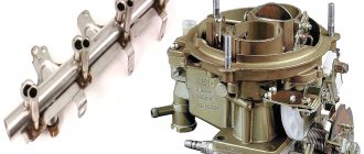
Supply system
All ZMZ 53 engines were equipped with a power system with a carburetor. In addition to this device, the system included a fuel pump, a tank or system of tanks for storing fuel reserves, filters and pipelines for connecting the system components. Below we will consider the general structure of the main unit of the power system - the K 135 vertical carburetor.
This model replaced the K 126 model in 1985. The appearance of the new device was associated with the modernization of the ZMZ engine family. The body of the new carburetor has not changed; in fact, only the flow sections of the jets have changed.
A valve vacuum line fitting for the exhaust gas recirculation system was added to the housing.
Operating modes, ideal carburetor characteristics.
The power of internal combustion engines is determined by the energy contained in the fuel and released during combustion. To achieve more or less power, it is necessary, accordingly, to supply more or less fuel to the engine. At the same time, combustion of fuel requires an oxidizer—air. It is the air that is actually sucked into the engine pistons during the intake strokes. By using the gas pedal connected to the carburetor throttle valves, the driver can only limit the access of air to the engine or, on the contrary, allow the engine to fill to the limit. The carburetor, in turn, must automatically monitor the air flow entering the engine and supply a proportional amount of gasoline.
Thus, the throttle valves located at the outlet of the carburetor regulate the amount of the prepared mixture of air and fuel, and therefore the engine load. Full load corresponds to maximum throttle openings and is characterized by the greatest flow of combustible mixture into the cylinders. At "full" throttle, the engine produces the most power achievable at a given speed. For passenger cars, the share of full loads in actual operation is small - about 10...15%. For trucks, on the contrary, full load modes occupy up to 50% of the operating time. The opposite of full load is idle. In relation to a car, this is the operation of the engine with the gearbox turned off, regardless of what the engine speed is. All intermediate modes (from idle to full load) fall under the definition of partial load.
A change in the amount of mixture passing through the carburetor also occurs at a constant throttle position in the event of a change in engine speed (the number of operating cycles per unit time). In general, load and rotation speed determine the operating mode of the engine.
A car engine operates in a huge variety of operating modes caused by changing road conditions or the desire of the driver. Each driving mode requires its own amount of engine power, each operating mode corresponds to a certain air flow and must correspond to a certain mixture composition. Mixture composition refers to the ratio between the amount of air and fuel entering the engine. Theoretically, complete combustion of one kilogram of gasoline will occur if slightly less than 15 kilograms of air are involved. This value is determined by the chemical reactions of combustion and depends on the composition of the fuel itself. However, in real conditions it turns out to be more profitable to maintain the composition of the mixture, although close to the named value, but with deviations in one direction or another. A mixture in which there is less fuel than theoretically required is called lean; in which there is more - rich. For quantitative assessment, it is customary to use the excess air coefficient a, showing the excess air in the mixture:
Design and purpose of the carburetor for 135
The Gas-53 carburetor consists of several parts. Fuel consumption is controlled by independent fuel mixture control systems. Characteristics of the gas 53 carburetor has a two-chamber drive for synchronous distribution of the combustible mixture. The modification and design of the carburetor for 135 is equipped with a balanced type float chamber, this makes it possible to simultaneously open the dampers.
Diagram of the K-135 carburetor and speed limiter sensor: 1 - accelerator pump: 2 - float chamber cover; 3 — air jet of the main system; 4 — small diffuser; 5 — idle fuel jet; 6 — air damper; 7 — accelerator pump nozzle; 8 — calibrated economizer sprayer; 9 — discharge valve; 10 — idle air jet; 11 — fuel supply valve; 12— mesh filter; 13 - float; 14 — sensor valve; 15 - spring; 16 — sensor rotor; 17 — adjustment wing; 18 — viewing window; 19 - plug; 20 - diaphragm; 21 — limiter spring; 22 — throttle valve axis; 23 — limiter vacuum jet; 24 - gasket; 25 — restrictor air jet; 26 — cuff; 27 - main jet; 28 - emulsion tube; 29 — throttle valve; 30 — idle speed adjustment screw; 31 — mixing chamber housing; 32 — bearings; 33 — throttle valve drive lever; 34 — check valve of the accelerator pump; 35 — float chamber body; 36 — economizer valve.
This is interesting: Step-by-step instructions for installing fender liner
Thanks to the improved intake, it was possible to achieve a more homogeneous working mixture. A new cylinder head, paired with a manifold, with high-quality tuning, leads to a reduction in toxicity. The carburetor for 135 is equipped with helical channel walls, with an increased compression ratio, allowing you to save up to 7% of fuel.
Main dosing system
The uniform, constant composition of the working fuel mixture is ensured by the main dosing system. The characteristics imply the installation of fuel and air jets on each chamber; the gas 53 carburetor contains an air atomizer as part of the dosing system. The constant composition of the mixture ensures stable operation at medium speeds of the car.
Parameters of the metering elements of the K-135 carburetor
Idle system
Stable and uniform idle speed on a gas carburetor is achieved by the position of the throttle valve. The fuel mixture enters the working part when bypassing the gas pump; the flap for unhindered access to the cylinders must be slightly open in the correct position.
Diagram of the K 135 idle system: 1 - float chamber with a float mechanism; 2 - main fuel jet; 3 - emulsion well with emulsion tube; 4 — “quality” screw; 5—via hole; 6 — fuel supply valve to the idle system openings; 7 — idle air jet; 8 air jet plug; 9 — idle fuel jet; 10 — inlet air pipe.
The design of the carburetor for 135 provides for adjustment of the XX system. The setting directly affects fuel consumption; the quality and quantity screws adjust the mixture supply parameters.
Float chamber
The elements of the float chamber are:
- A locking mechanism, the needle with a membrane of which is installed in the valve seat;
- A float that regulates the amount of fuel mixture in the chambers.
Scheme for checking the fuel level in the carburetor float chamber for 135: 1 - fitting; 2 — rubber tube; 3 - glass tube.
The main purpose of the carburetor float chamber for 135 is to maintain the fuel level for stable operation of the car. The chamber is installed in the main body of the carburetor.
Economizer
The economizer is responsible for realizing the full engine power. The device includes a valve that supplies fuel through channels, bypassing the GDS.
Carburetor economizer for 135
The gas 53 carburetor is designed in accordance with toxicity standards; at stable loads, access to the combustion chamber is blocked from excess fuel.
Acceleration pump
Scheme of the carburetor accelerating pump: 1 - rod; 2 — bar; 3 - well; 4 - spring; 5 - piston; 6 - check valve; 7 - traction; 8 — lever; 9 — throttle valve; 10 - discharge valve; 11 - sprayer.
When you press the accelerator all the way while driving, the accelerator pump built into the carburetor of the 135 model takes over. Fuel is supplied to the 135 by a piston in a cylindrical channel, which begins to enrich the mixture. The device is made with a mixture sprayer, due to this, the car picks up speed smoothly, without jerking.
Speed limiter
The system operates on pneumatics, the movement of the diaphragm occurs due to vacuum, turning the axis of the throttle valves. Mechanically connected to the limiter, the gas 53 carburetor system does not allow the throttle valves to open completely. The engine speed is controlled by the throttle.
Starting system
A cooled engine is started by the starting system. The process goes like this:
- The choke drive lever, attached to the car interior, is pulled out to the required distance;
- The lever system slightly opens the throttle of the air damper drive, thereby shutting off the air.
The launch is carried out by enriching the mixture and controlling the fuel supply. The characteristics of the K135 device are designed in such a way that the car engine does not stall. The air damper has a valve, under the influence of vacuum, which opens air to prevent an overly rich mixture.
Features of the modernized engine
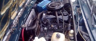
The K 135 carburetor (like the K 126) has two chambers, each of which provides 4 cylinders with a working mixture. On older versions of engines there was an intake manifold with intersecting channels at different levels. The first chamber fed cylinders 1, 4, 6 and 7, the second – 5, 2, 3 and 8. The carburetor compartments worked in accordance with the order of flashes in the engine parts. The old type collector is pictured below.
On the modernized engine, the manifold was simplified, and each chamber began to be responsible for the cylinders of its own block. This solution reduced the cost of the collector. But uneven pressure pulsations arose in the chambers of the K 135 carburetor. Due to such pulsations, a scatter in the characteristics of the mixture occurs in different cylinders and at different moments of engine operation. The new collector can be seen in the photo.
But thanks to the new jets, it was still possible to improve the toxicity standards of GAZ 53 engines. The K 135 carburetor ensured the preparation of leaner working mixtures, which slightly smoothed out the heterogeneity of the mixture. A new manifold and carburetor, along with new cylinder heads with an increased compression ratio and helical intake port walls, improved the engines' fuel efficiency by 6-7%. At the same time, the requirements for the octane number of gasoline have not changed.
Carburetor malfunctions
Failure to comply with the periodicity of vehicle maintenance can lead to breakdowns. Malfunctions in the fuel supply of the gas 53 carburetor device stop normal operation for various reasons and conditions. When identifying faulty components, it is necessary to determine which unit is malfunctioning during operation. There are times when breakdowns are caused by incorrect operation of the ignition system. Before repairing, it is necessary to check the ignition system for the presence of a spark. The carburetor to 135 should be opened only in cases where the fuel supply system has been checked. Fuel supply may be difficult due to clogged fuel lines or hoses.
The main malfunctions in the operation of the gas 53 carburetor may be enrichment or over-depletion of the mixture. Both factors may be the result of incorrect adjustment to the 135, lack of tightness in the system, or clogging of the fuel supply system.
- High fuel consumption, unstable idling;
- Dips during acceleration or increased loads, a consequence of jamming of the accelerator pump drive piston;
- Clogged jets. Occurs in an aggressive operating environment, faulty filters;
- Depressurization of the body of the float chamber K135 leads to a lean mixture when the internal combustion engine operates unstably in certain modes;
- Fuel overflow into the combustion chamber due to malfunctions of the float system needle leads to difficulty starting the car.
Washing and purging of systems with air flow and units is carried out when one of the causes of unstable operation is identified, as well as as a preventative measure. Typically, it is recommended to entrust gas 53 carburetor repair to specialists; they are equipped with the necessary tools and skills for high-quality work. You can adjust the idle speed groove with your own hands by removing the air filter.
What does it consist of?
Each carburetor has systems that help it function properly under certain conditions. There are also additions that help them function properly (for example, these include solenoids designed to cut off the fuel supply or pressure surge absorbers). It is not recommended to remove such components, as this will have a noticeable effect on engine operation.
So, any carburetor for GAZ-53 will consist of the following parts:
- Float chamber;
- Air damper;
- Idle system;
- Acceleration pump;
- Transition system;
- Main carburetor metering system;
- Economizer.
K-126 carburetor diagram
Adjustment and repair
Without completely disassembling the device, it is possible to adjust only the idle level with your own hands. Fuel consumption depends directly on the crankshaft speed. The principle of operation involves adjusting the gas carburetor with 53 quality and quantity screws.
There are several adjustments:
- The amount of gasoline in the float chamber;
- Setting up the economizer operation;
- Accelerator pump piston stroke;
- Number of revolutions, idle jet.
Correct idle speed control is carried out on a working engine. Usually the procedure is performed after prophylaxis in order to exclude other possible causes of unstable operation.
Type of carburetor without cover: 1 economizer rod; 2 drive bracket for echonomizer and accelerator; 3 — accelerator piston; 4 - main air jets; 5 — accelerator pump fuel supply screw; 6 — “quality” screws; 7 — “quantity” screw
The process and scheme for adjusting the idle speed on the 53 carburetor is the following operating principle:
- The adjusting screws of a cold engine are tightened until they stop, then unscrew 3 full turns. It is possible to adjust the carb using a slotted screwdriver;
- Warm up the engine to operating temperature;
- The number of revolutions to 135 is adjusted by ear with a screw, since the car is not equipped with a tachometer. The revolutions should be kept between high and low, weaving and jerking are unacceptable;
- The K135 quality screw is tightened until the level of engine interruptions begins; it is necessary to adjust it gradually, adjust the groove with your own hands, until normal, stable operation is achieved.
- The quantity is adjusted on both chambers, parallel to each other;
- In cases where the car stalls when releasing the gas, it is possible to increase the operating speed.
Repair of the gas 53 carburetor is carried out in case of significant damage to the components or detected contamination. Flushing is carried out on demand; too frequent a procedure can forget the fuel supply channels and damage the devices. The most common method is to clean the float chamber. Deposits are removed only with the top layer, since stuck-on dirt can get into the inlet part of the channels and disrupt the operation of all systems. The causes of soot and deposits are poor quality or old fuel filters. Carburetor gas 53 when flushing, you should immediately replace all fuel and air filters.
During the disassembly process, it is necessary to check the condition of all elements of the system. We will repair jets, dampers and the accelerator pump, which have thin channels that, when clogged, affect engine operation.
Maintenance and possible adjustment of the gas 3307 carburetor installed on a gazelle car does not require complete removal from the engine. The plant has provided that dismantling the air filter makes it possible to routinely check the condition and adjust the idle speed. When completely cleaning and replacing components, the assembly is removed from the engine. Proper technical operation and filter replacement make the need for a complete overhaul minimal. It is enough to carry out preventive maintenance as contamination occurs in the form of flushing the K-135 carburetor.
Flushing is carried out using a flammable liquid. There are special means, the principle of which allows liquid to be delivered under air pressure to hard-to-reach places and grooves. External washing is carried out with a brush until deposits and dirt are completely removed. Care should be taken when washing internal parts, as there is a possibility of breaking seals or clogging the channels with dirt.
Existing insertion methods
For each car model, appropriate gas equipment is selected. Inserting an LPG into a second-generation carburetor is no different from the first LPG. The master selects the best option individually, taking into account the design of the machine.
The simplest option is to install a spacer mixer equipped with a separator. Inserting gas into the carburetor in this way has the main advantages:
- the carburetor body is not subject to mechanical stress;
- there is no drilling process.
This option is often used for inserting gas fittings in carburetors, such as “Ozone”. To do this, remove the textolite gasket and install a gas mixer. This technological operation can be performed on any conventional carburetor.
The installed gas mixer is equipped with a power register. The design provides two outputs, with the possibility of autonomous adjustment. Thanks to the register, you can set the optimal gas supply. This allows you to significantly reduce gas consumption and obtain the best dynamic characteristics. Simple installation has made this method highly popular.