The operation of the contact transistor system is based on the use of semiconductor devices. Advantages of the contact transistor system compared with battery ignition system the following:
- A small transistor control current passes through the contacts of the breaker, and not the current (up to 8 A) of the primary winding of the ignition coil (erosion and wear of the contacts are eliminated).
- The high voltage current and spark discharge energy increase (this allows the gap between the spark plug electrodes to be increased, makes it easier to start the engine, and makes the engine more economical).
First, let's figure it out
How does a contact-transistor ignition system work?
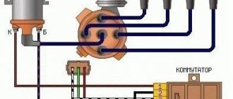
If the ignition switch 17 is turned on and the breaker contacts are open, then the transistor 21 is locked, since there is no current in its control circuit, i.e. in the emitter-base junction. Current does not pass between the emitter and collector to ground, since the resistance of this junction is very high. When the breaker contacts are closed, current flows in the transistor control circuit (emitter-base), causing the transistor to open. The control current is small (about 0.8 A) and decreases to 0.3 A with increasing speed of the chopper cam. In the contact-transistor ignition system there are two low voltage circuits: the transistor control circuit and the operating current circuit.
Transistor control circuit: positive terminal of the battery 16 - ignition switch 17 - terminals VK-B and K of additional resistors 14 - primary winding 4 of the ignition coil 5 - terminal of the transistor switch 1 - transition electrodes emitter - base of the transistor 21 - primary winding of the pulse transformer 20 - terminal P – contacts 11 and 12 of the breaker – ground – negative terminal of the battery. When the transistor control current passes through the emitter-base junction, the emitter-collector resistance significantly decreases, and the transistor opens, including the operating current circuit (7-8 A).
Low voltage operating current circuit
Positive terminal of the battery 16 - ignition switch 17 - terminals VK-B and K of additional resistors 14 - primary winding 4 of the ignition coil 5 - terminal of the transistor switch 1 - electrodes of the emitter-collector transition of the transistor 21 - terminal M - ground - negative terminal of the battery. When the breaker contacts open, the current in the transistor control circuit stops and its resistance increases significantly. The transistor closes, turning off the low voltage operating current circuit. The magnetic flux of the changing field crosses the turns of the ignition coil, inducing an EMF in the secondary winding, resulting in a high voltage (about 30,000 V), and a self-inductive EMF in the primary winding (about 80-100 V).
High voltage circuit
Secondary winding 6 of the ignition coil 5, rotor 9 of the distributor 10 – spark plugs 7 (in accordance with the engine operating order) – ground – secondary winding 6 of the ignition coil 5.
A pulse transformer is needed to quickly turn off the transistor. When the breaker contacts open, a self-induction EMF is induced in the secondary winding of the pulse transformer, the direction of which is opposite to the direction of the operating current at the base-emitter junction. Thanks to this, the magnetic field and current quickly disappear in the primary winding 4 of the ignition coil 5. Diode 19 and zener diode 18 in the forward direction - past the primary winding of the ignition coil.
It must be remembered that the breaker contacts only pass and interrupt the transistor control current of 0.3-0.8 A. If oil gets on them, an oil film or an oxide layer has formed, then the transistor control current will not be able to pass through the contacts. Therefore, the breaker contacts are washed with gasoline and ensure that they are always clean.
General operating principle
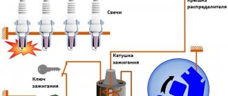
The presence of a contact ignition system in a car means that the ignition of the fuel in the cylinders is carried out upon the appearance of a spark from the spark plug.
In this case, the spark itself occurs when a high voltage pulse arrives from the ignition coil.
The key function is performed by the ignition coil, which, according to its operating principle, resembles a transformer.
It consists of two windings (primary and secondary) wound on a metal core.
First, voltage is applied to the primary winding, after which a current is created in the coil.
As soon as a short-term break in the primary circuit occurs, the magnetic field is leveled, but a high voltage (about 25,000 Volts) appears in the secondary winding.
At this moment, a voltage of 300 Volts is also present on the primary winding.
The reason for its appearance is self-induction currents. It is because of the appearance of this current that the breaker contacts burn and spark.
From the above we can conclude that the secondary voltage directly depends on the following aspects:
- Magnetic field;
- The intensity level of the current drop in the primary winding.
To increase the secondary voltage and reduce the risk of burning the contact group, a capacitor is included in the circuit (installed in parallel). Even with a slight opening, the capacitor is charged.
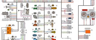
A schematic diagram of the contact ignition system is shown below.
Currently reading Why do spark plugs turn black?
17.1k
Immobilizer locked, how to start the engine
23.5k
The capacitance discharge occurs through the primary winding, through the formation of a reverse voltage pulse current. Thanks to this feature, the magnetic field disappears and the secondary voltage increases.
The optimal capacitor capacity for a contact ignition system is 0.17-0.35 µF. For example, domestically produced Zhiguli cars have a capacitor with a capacitance of 0.2-0.25 μF (at a frequency of 50 to 1000 Hz).
If the vehicle's ignition system operates without failure, the secondary voltage should constantly increase. It depends on two main parameters - the size of the gap between the spark plug electrodes, as well as the pressure in the cylinders of the machine.
For a contact ignition system, this parameter (secondary voltage) should be at the level of 8-12 Volts.
In order for the system to operate without failures, at the moment of interruption the mentioned indicator increases to 16-25 kV. The presence of such a reserve allows you to avoid adverse consequences from certain fluctuations in the ignition system.
The problems mentioned above include adjustments to the composition of the combustible mixture or changes in the distance between the spark plug electrodes.
For example, a decrease in the oxygen level in the fuel-combustible mixture leads to an increase in voltage to 20 kV.
Despite a number of measures taken, the creators of the contact ignition system were unable to completely avoid burning the contact group. The optimal way to reduce this effect is to strictly maintain the gap at a minimum level (0.3-0.4 mm).
As an example, we can cite domestic VAZ cars, in which the gap in the breaker is 0.35-0.45 mm, which corresponds to an angle of 52-58 degrees (provided that the contact group is in a closed state).
If this angle changes, the voltage in the secondary winding is also adjusted. As a result, sparks appear not only on the contacts, but also on the sliders. For this reason, the quality of the spark decreases and the engine loses power.
The reliability of the contact ignition system, which depends on a number of factors, deserves special attention:
- Shape, energy and time of spark appearance;
- The number of sparks in a certain area;
- Secondary voltage (one of the most important characteristics). The larger this parameter, the less dependent the system is on the composition of the combustible mixture and the level of cleanliness of the electrodes.
Tuning on carburetor modifications of the VAZ 2107
All old textbooks on servicing classic Zhiguli models describe a method for setting the moment of spark formation using a light bulb, although experienced motorists can easily do without it. You will understand why this happens as you read this material, but for beginners it will be useful to familiarize yourself with the old proven technique.
To correctly set the ignition of the “seven”, you need to ensure that the following conditions are met simultaneously:
- the notch on the crankshaft pulley is opposite the long mark on the timing cover;
- in this case, the round mark marked on the camshaft chain drive gear coincides with the boss on its body;
- the piston of the 4th cylinder has completed the compression stroke and is at top dead center;
- the contacts inside the distributor are open;
- The movable contact of the slider faces the fixed contact on the distributor cover, where the wire from the spark plug of the 4th cylinder is connected.
The diagram shows what happens in the cylinders when the marks are aligned
The light bulb is used to control the ignition timing, for which it must be connected with one wire to the “K” contact of the high-voltage coil, and with the second to the vehicle ground. You should know that at the same moment the piston of the first cylinder is also in the TDC position, only there the air-fuel mixture is not compressed, but exhaust gases are released after its combustion. This is why ignorant car enthusiasts often confuse the first cylinder with the fourth when installing the ignition.
Layout of marks on the timing cover
When the above actions occur simultaneously, a spark discharge occurs on the electrodes of the spark plug of the 4th cylinder, as evidenced by the flash of the connected light bulb. To achieve these conditions and set the ignition correctly, follow the instructions:
- Turn the crankshaft with a 36 mm wrench, aligning the notch on the pulley with the long notch on the timing cover.
- If at this moment the engine valve cover is removed, then it is better to navigate by the mark on the camshaft gear, placing it opposite the housing boss.
- Take the ignition distributor, remove the cover and turn its shaft to place the slider opposite the wire leading to cylinder No. 4 (there are cylinder number markings on the cover). Insert the distributor into the engine hole, holding the slider and housing in this position, and then secure it with a 13 mm wrench nut.
- Connect the light bulb wires and turn on the ignition by turning the key. Loosen the nut securing the distributor and slowly turn it by the housing until the lamp flashes, indicating the moment of sparking. Reattach the distributor.
- Turn off the ignition and make sure that the contacts inside the distributor are currently open. Take a 0.35 mm feeler gauge and check the gap between them, if necessary, adjust it by loosening the fastening screws with a screwdriver.
The marks must be aligned by turning the crankshaft with a wrench
The ignition is considered to be set correctly if, after installing the distributor cap and connecting the wires, you manage to start the engine, and then you need to adjust the timing. The non-contact system is installed in the same way, with the exception of checking the gap in the contact group due to its absence.
The mark on the camshaft gear is aligned with the boss on the body
Important point. In most cases, the ignition is set without removing the valve cover, which is why the position of the mark on the gear is not visible. You have done everything according to the instructions, but the engine does not start. This means that a spark is supplied to the 4th cylinder during the exhaust stroke, and compression at this moment occurs in the first cylinder. The problem can be solved simply:
- remove the distributor cover;
- unscrew the nut securing it;
- pull the distributor out of the socket, turn the slider exactly 180° and insert the element back;
- Press the distributor skirt with the nut and install the cover.
Contactless sensor: who is it and how is it useful?
In fact, the contactless ignition system, the operating principle of which we are considering today, is not structurally very different from its predecessors.
The operating algorithm remained the same, but it completely lost any mechanical contacts in the low-voltage part. To understand how everything works, let's take a look at the design of the contactless system. It consists of the following elements:
- battery and generator;
- egnition lock;
- pulse sensor;
- transistor switch;
- ignition coil;
- distributor;
- ignition timing regulators;
- candles.
As you may have noticed, many of these elements are already familiar to us. Fundamentally new in the list of components of the contactless ignition system is the pulse sensor, which replaced the breaker present both in the classic contact circuit and in its more advanced transistor version.
Using a special element, it monitors the engine crankshaft speed. Such an element can be a Hall sensor (the most common option), which generates electrical pulses depending on changes in the magnetic field, an optical sensor, or an inductive one.
The impulses created by it, generated precisely at those moments when it is necessary to create a spark in the candle, enter the commutator.
If you have read previous articles, then remember that the basis of the switch is a transistor - an electronic device that can control large currents using small ones.
It is this that is affected by the same electrical impulses from the sensor, and it, in turn, controls the operation of the ignition coil, which converts the low voltage of the on-board network into a much higher one, necessary for the formation of a spark (about 30,000 Volts).
By the way, the pulse sensor is combined into one housing with a distributor and together they form a single device, which is called a sensor-distributor.
conclusions
All systems used to ignite a fuel mixture are good in certain areas of mechanical engineering. Everyone is not without their shortcomings. It is not always necessary to create a complex and highly reliable system; sometimes it is much cheaper to use simple and cheaper ones. There is no need to install an expensive ignition system on a car that is much lower in cost than others in its class. Such actions can only increase its cost, but the quality, unfortunately, will remain the same. Why change anything if the ignition system has shown only the best results in many tests?
Device
The ignition system of the GAZ 53 car is currently contactless. Having studied the device and principle of operation, you can simultaneously master troubleshooting skills. This is especially necessary for those who operate GAZ 53. After all, it often happens that there are no good specialists nearby who would help in solving problems that arise. In addition, you will have to pay for their services. The quality of the work done can sometimes be determined after some time. A malfunction that occurs unexpectedly and at the wrong time will create trouble.
System elements
The ignition system of the GAZ 53 car consists of several elements, each of which performs its own function. Knowing them, you can find and fix the problem much faster. The system consists of the following elements:
- Rechargeable battery;
- Switch;
- Spark plug;
- Sensor distributor;
- High-voltage and low-voltage wires;
- Ignition coil;
- Additional starter relay;
- Additional and noise suppression resistor;
- Current indicator;
- Egnition lock.
All constituent elements can be grouped depending on the tasks performed. In this case, they will be included in the appropriate groups. The ignition system of the GAZ 53 car will work correctly when the basic conditions are met:
- Comparison of the moment of spark occurrence and engine operation;
- Sufficient spark power;
- No gaps in sparking.
To supply a spark in a timely manner, you need to carefully correlate the engine operating cycles and the appearance of voltage on the spark plug electrodes. The required spark power, in turn, depends on the voltage, the gaps between the electrodes of the spark plug and the serviceability of the circuit. The lack of a spark leads to a decrease in power and an increase in fuel consumption, so misfires are unacceptable.
A Timely Spark
Comparison of a certain stroke and voltage supply to the spark plugs is the task of the distribution sensor. The contactless ignition system of the GAZ 53 car can be equipped with a magnetoelectric or semiconductor sensor-distributor, which is located inside the distributor. The list of distributor elements includes:
- Sensor-distributor;
- Current carrying plate (runner);
- Centrifugal and vacuum regulator.
The GAZ 53 magnetoelectric sensor is a generator of alternating current pulses, the frequency of which depends on engine speed. This device has eight poles (according to the number of cylinders). During the rotation of the camshaft, and with it the sensor rotor, the poles of the permanent magnet sequentially pass through the poles of the stator winding. As a result of the changing magnetic flux, an induced emf is induced in the winding, which creates a control pulse for the commutator.
The centrifugal regulator rotates the sensor rotor relative to the stator, which, in turn, changes the ignition timing of the GAZ 53. This occurs when the engine crankshaft speed increases. The regulator weights, overcoming the force of the springs, turn the rotor. Thus, the effort must be certain, otherwise it will affect the operation of the GAZ 53.
The vacuum regulator rotates the stator relative to the rotor, changing the angle. It operates depending on the load and engine speed.
Power and spark quality
It's no secret that a good spark is the key to high-quality ignition of a combustible mixture. The ignition system of a GAZ 53 car will have a good spark if the following conditions exist:
- The gap between the spark plug electrodes is correctly adjusted;
- Serviceable ignition coil;
- The desired shape of the commutator pulses;
- Good quality high voltage circuit.
If the gap between the spark plug electrodes is too small, ignition of the air-fuel mixture will be difficult. Because of this, a gap may occur not in sparking, but in ignition. The consequences are the same.
The serviceability of the ignition coil is manifested in its ability to induce the required voltage without interruptions (skips). As a rule, a faulty coil makes itself known by a characteristic decrease in the quality of operation of all eight cylinders. If it is determined that the coil is faulty, then it must be replaced with one of the same type, with the same markings. This GAZ 53 part consists of two windings: primary and secondary. The latter contains many more turns than the first. The windings are wound one on top of the other on a magnetic core. The entire structure is housed in a sealed housing filled with plastic. The malfunction of this part is associated with a short circuit, which can be interturn and to the housing.