01/26/2022 3,799 VAZ 2107
Author: Ivan Baranov
In any case, car optics must be in working order, since the safety of the car depends on it. Especially when it comes to rear lights, because it is through them that drivers of cars walking behind can learn about the maneuvers that the car is about to make. For what reasons do the rear lights of the VAZ 2107 not work and how to replace them - we will talk about this below.
[Hide]
Tinting the rear lights of VAZ 2107
This is one of the popular, simple and cheap types of car tuning. With its help, you can give a stylish appearance with minimal time and money. In practice, two methods of tinting are used: paint and film. It cannot be said that one is worse or better - they both have advantages and disadvantages.
To tint headlights with paint you need a special heat-resistant varnish. To tint you will have to remove and disassemble the taillights. The order of operations is as follows:
- Open the lid in the trunk trim.
- Remove the board with lamps.
- Unscrew 4 screws.
- Move the upholstery to the side.
- Disconnect the flashlight connector.
- Unscrew the nuts securing the lamp to the body.
- Take out the flashlight.
- Remove the glass.
- Clean the surface.
- Clean the glass with sandpaper
- Apply paint.
- Assemble and install the rear light.
Painting with varnish should be carried out in a clean room so that dirt or dust does not get on the surface to be painted. Before painting, the surface must be prepared by thoroughly cleaning and degreasing it. You need to apply paint from a can from a fairly large distance, otherwise it will “float”. Painting should be done in several (5-6) layers. Each layer is applied to the dried previous one.
The taillights of the VAZ 2107 can also be tuned using a tint film. In this case, the film is applied to the glass instead of varnish. What to consider when gluing film to lights:
You need to use more expensive and high-quality film.
It is better not to use film with low light transmittance. In addition to black, you should pay attention to red and other colors of film. They often look even more impressive and original. You can apply not full, but partial film tinting
This helps transform the appearance of your headlights without reducing their brightness. After tinting the lights, it is worth replacing the standard lamps with more powerful ones to compensate for the loss of brightness.
How to improve and brighten
The taillights of any car are a sign of driving safety. They are the ones who show the cars behind us what we are going to do or are already doing. On a clear day, the brightness of the standard lamps in the flashlights may not be enough, so it makes sense to increase this brightness.
Such a modification does not threaten any troubles, since it is impossible to dazzle even with bright “stop lights” or “turn signals”. How to increase brightness at minimal cost? The simplest option is to replace the standard lamps with halogen ones, which create a greater luminous flux.
Such lamps can be installed on the reverse gear, brake light and turn signal. You shouldn't put them on the fog light. This power will simply melt the glass during prolonged operation.
Important! When installing such lamps, the fuses responsible for their operation may blow out. The issue is resolved by installing fuses of a higher rating.
But, of course, they will not fit into the rear light fixtures. It takes a decent amount of time to ignite them - up to 5 seconds. or more, and the taillight lamps must react with lightning speed. We don’t want the brake light to come on when someone drives into us. And a turn signal that blinks once after performing a maneuver will not add safety. In addition, installing expensive ignition units on brake lights is stupid, to say the least.
But “halogen” lamps, of course, are not the best option - incandescent lamps, especially halogen ones, do not tolerate constant switching on/off and will quickly burn out. The best option is an LED light source, which creates an increased luminous flux.
A more labor-intensive option is to install LEDs or LED strip yourself. It is good because it will not only increase the brightness of the light fixture, but also improve its appearance.
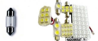
Tuning with LEDs
We will be tuning with LED modules and an LED strip with 5050 LEDs with a power of 0.21 W each.
We remove the rear lights, remove the glass and circuit board from them and put them aside. Naturally, we will not modify the glass. Now, from plexiglass or any other suitable material, we cut out the inserts for the brake signal window and turn signal. We will leave the standard lamps in the fog light and reverse signal.
Now we cut the tape into strips of 9 LEDs. We cut strictly in the places indicated by the manufacturer - they are most often marked on the tape with scissor icons.
In total, you will need 5 segments for the turn signal and two for the side light. We solder the segments together, observing the polarity (marked on the tape). For turns and dimensions, of course, separately.
There will be three modules in the braking signal; we also solder them together. Using double-sided tape, glue the turn strips and above them one marker light strip onto the insert. We install the insert itself in place and fix it with sealant. We lead the power wires through the reflector into the hole for the turn signal lamp - it won’t be there anyway.
Important! We connect the tape responsible for the side light so that it glows red. To do this, you need to supply power to the +12V and R contacts.
We do the same with the modules - we glue them onto the brake light insert, and glue the insert into place using sealant.
Now, using the same sealant, we glue the second tape of the side lights to the place indicated by the arrows in the photo. Naturally, we glue it with the edge to the partition.
We remove the turn signal, side light and brake signal bulbs from the board. We solder the wires from our new lighting devices to the corresponding tracks of the board (see photo from the “Connection diagram” section). At the same time, we observe the polarity: minus of the tape and modules - to the ground track, pluses - to the tracks that powered the corresponding light bulbs.
We install the board in place, assemble the flashlight, install it on the car, and connect the power connector. Turn it on and check it.
In the photo the brake light is on and the side light has turned into a strip. The brake light appears yellow, but is actually bright red - it's just poor camera color rendering. The turn signal is not turned on, and the problem is very clearly visible: the LEDs shine through the glass, which, to put it mildly, is not entirely aesthetically pleasing. We were clearly in a hurry with the installation of the lantern. Well, we'll have to solve this issue with tinting. It will not only hide the LEDs, but also decorate the car.
Tinting
This operation can be carried out in two ways: using a tinting film and a special tinting varnish. We'll try both.
Varnish tinting
We go to a car store and buy a special tinting varnish. We remove the headlight, remove the glass from the headlight. Some people simply cover the body with masking tape and tint it directly on the car, but we won’t do that. Wash and dry the glass thoroughly.
Carefully read the instructions for the varnish (it is in an aerosol can) and cover the glass with the first layer, spraying the varnish from a distance of 25-30 cm. After the layer has dried, apply the second one and after it has dried, check the result by assembling the headlight and connecting it to the on-board network.
The main thing is not to overdo it with tinting. On the one hand, a thick layer of varnish will have a very presentable appearance, on the other hand, it will greatly weaken the light of the light bulbs. We will paint without fanaticism, in two layers. The LEDs and red glass of the brake lights are not visible through it - that's enough. We install the lantern in place and admire it.
Film tinting
You can tint with film by car, so we won’t remove the light fixture. Just wash the glass thoroughly. We cut a piece of film to the size of the lantern with an allowance of a centimeter on each side.
Spray the glass with a weak soap solution, remove the protective layer from the film and apply it to the glass. Using a rubber spatula, carefully rub the film from the center to the edges, expelling water from under it. We cut off the excess with a stationery knife or sharp scissors and grind the edges.
Another tuning option with self-installed discrete ultra-bright LEDs is presented in the video below. Here the side light is combined with a brake signal.
Illuminated license plate VAZ-2107
To illuminate the license plate in VAZ-2107 cars, AC12–5-1 (C5W) type lamps are used. The license plate illumination is turned on by the external lighting switch - the first button on the left under the gear shift lever. To replace the license plate light bulb, you need to lift the trunk lid, use a Phillips screwdriver to unscrew the two screws holding the backlight light and remove the lampshade from the light housing, then replace the light bulb.
To illuminate the VAZ-2107 license plate, AC12–5-1 (C5W) type lamps are used.
The rear lights of the VAZ-2107 car are a key element of the lighting system and perform a number of functions related to the safety of the vehicle. Proper operation and timely maintenance will extend the life of the rear lights and ensure comfortable and accident-free driving. You can give your car a more modern appearance by tuning lighting fixtures, including taillights.
INSTALLATION OF LIGHTING DEVICES
Installing components on a VAZ 2107 car will not cause any particular difficulties. The procedure is as follows:
- Open the trunk and use a screwdriver to remove the canopy cover that closes it from the inside.
- Use a wrench to unscrew the fastening nuts and unplug the electrical connector.
- Carefully remove the flashlight unit from its seat and clean it of dirt with a rag.
- We install new taillights instead of the old ones and secure them, after inserting a sealing gasket.
Upon completion of the installation of the lights, we connect them and check their functionality in all modes. The installation of new lighting devices on a VAZ 2107 car that complies with regulatory documents does not require registration.
Headlight adjustment
It is generally accepted that headlights perform their function if the road in front of the car is well lit and oncoming drivers are not blinded. To achieve such operation of lighting fixtures, they must be adjusted correctly. To adjust the VAZ-2107 headlights you need to:
- Place the car on a flat, strictly horizontal surface at a distance of 5 m from a vertical screen measuring 2x1 m. The car must be fully fueled and equipped with all the necessary equipment, the tires must be inflated to the required pressure.
- Draw a marking on the screen on which line C will indicate the height of the headlights, D - 75 mm below C, O - the center line, A and B - vertical lines, the intersections of which with C form points E, corresponding to the centers of the headlights. J is the distance between the headlights, which in the case of the VAZ-2107 is 936 mm.
- Move the hydraulic corrector regulator to the extreme right position (position I).
- Place a load weighing 75 kg on the driver's seat or place a passenger there.
- Turn on the low beam and cover one of the headlights with an opaque material.
- Achieve alignment of the lower boundary of the beam with the E–E line by rotating the adjusting screw on the rear side of the headlamp.
- Using the second screw, align the break point of the upper border of the beam with point E.
The same must be done for the second headlight.
Fog lights
Driving a car in rain or snow can create a lot of trouble for the driver who is forced to drive the car in poor visibility conditions. In this situation, fog lights (FTL) come to the rescue, the design of which provides for the formation of a light beam that “spreads” over the surface of the roadway. Fog lamps are usually yellow, since this color tends to dissipate less in fog.
Fog lights are usually installed under the bumper, at a height of at least 250 mm from the road surface. The installation kit for connecting PTF includes:
- set of wires;
- relay;
- button.
In addition, a 15 A fuse will be required, which will be installed between the relay and the battery. The connection should be made in accordance with the diagram supplied with the installation kit.
The fog lights must be connected in accordance with the diagram supplied with the installation kit.
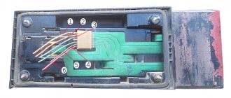
Design of the rear lights of the VAZ 2114
In order to carry out repairs, diagnose and eliminate emerging problems, it is necessary to understand the design and diagram of the rear lights of the VAZ 2114. The rear light design consists of three main elements: - the rear cover; — boards with fasteners, connections for connecting light bulbs; — external decorative cover, light diffuser.
Wiring diagram for components (lamps): 1. direction indicators; 2. overall glow; 3. signaling (brake lights); 4. foglights; 5. designations for reversing.
Causes of breakdowns
The most common reasons for node failure:
- the narrowest point in the entire structure is the elastic board;
- in second place, banal burnout or mechanical damage to light bulbs;
- the third reason is a problem with the fuse or relay;
- oxidation of contacts;
- broken wiring.
First of all, it makes sense to check those elements that do not require removing the entire headlight (for example, fuses, relays). Then check the quality of the connections, the presence of oxidation and the voltage supply level to the illuminator. The last step is to disassemble the taillight, remove and inspect the board.
VAZ 21074 engine control system diagram
Wiring diagram of electrical connections of ECM VAZ 21074 - circuit elements. 1 — controller connector; 2 — mass air flow sensor; 3 — coolant temperature sensor; 4 — crankshaft position sensor; 5 — throttle position sensor; 6 — oxygen concentration sensor; 7 — speed sensor; 8 — ignition module; 9 — solenoid valve for purge of the adsorber; 10 — electric fan relay; 11 — electric fuel pump relay; 12 - main relay; 13 - fuse for the power circuit of the electric fuel pump relay: 14 - fuse for the power circuit of the main relay; 15 — fuse-link; 16-fuse protecting the constant power supply circuit of the controller; 17 - diode; 18 — idle speed regulator; 19 — nozzles; X1 - diagnostic block; X2 - connection block to the vehicle electrical system.
Front lights
The front part of the car usually attracts more attention, so amateurs begin to tune primarily the headlights.
Evil headlights
It’s very easy to give your car a menacing, gloomy and even evil look: just perform tuning like “evil headlights”. This is one of the easiest ways to give the “seven” an unusual appearance.
Depending on the owner’s capabilities, tuning can be done using a variety of materials:
- thin plywood;
- sheet metal;
- tinting film;
- paints.
The car's "angry" squint gives you goosebumps
The essence of this tuning is as follows: cover part of the headlight so that the remaining uncovered headlight resembles evil eyes. If any materials from plywood or metal are selected, then a blank is cut out in advance and glued into the cavity of the headlight. Using film or paint is even easier - just remove the headlight and apply darkening on the inside.
Tuning headlights from plywood painted black
Angel eyes
In tuning, angel eyes are the luminous rings on the “face” of a car - like a BMW. Today everyone can afford this lighting option - it’s inexpensive and fast. In addition, the body of the VAZ 2107 will somewhat resemble an expensive BMW and thereby increase the status of the owner.
Headlights that are very unusual for the “Seven”
There are several technical solutions for making angel eyes with your own hands. The easiest option is to use LEDs. To work you will need:
- white LEDs 5 mm - 2 pcs.;
- 0.25 W resistor;
- wiring;
- transparent rod made of organic glass or plastic (diameter 8–10 mm);
- auxiliary materials (soldering iron, hair dryer, drill and glass jar).
The work is quite painstaking:
- Take the rod and clamp it in a vice.
- Using a drill, drill holes for the LEDs at both ends of the rod.
- Give the rod the shape of a ring - bend it around the jar and heat it with a hairdryer so that the workpiece remains in this shape.
- Solder wires to the LEDs, connect a resistor to one of the wires.
- Assemble an electrical circuit similar to the circuit of lighting devices that is already available on the “seven”.
- Insert the LEDs into the holes of the workpiece and glue them with superglue.
Video: how to make angel eyes
You can buy ready-made angel eyes at a car store - this will make it much easier to connect new lighting fixtures to the standard equipment of the car.
Using LEDs of different shades, you can achieve an even more impressive effect.
What's new
The main innovation was the replacement of the mechanical functions of the ignition system and preparation of the air-fuel mixture with electronic devices, which are more accurate and efficient. The wiring diagrams of the VAZ 2112 and the Samara family also underwent a similar modernization. Accordingly, the wiring of the VAZ 2107 to the injector received differences from the carburetor version.
Under the hood of the VAZ 2107-20, the absence of a carburetor and distributor is immediately striking
ECM functions
The electronic engine control system (abbr. ECM) took on the following operating parameters of the power unit:
- Controlling the amount of air and gasoline entering the car engine cylinders,
- crankshaft speed
- Spark plug control;
- Adjustment of ignition timing in all operating modes;
- Turning the electric fuel pump on and off,
- Control of the electric fan of the engine cooling system.
The photo below shows a VAZ 2107 wiring diagram for an injector with an M1.5.4N ECM and a January-5.1.3 controller
Injection system VAZ 2107
Electrical diagram
The classic 2107 wiring on cars with an injection system has also undergone changes. In particular, under-hood elements equipped with connectors for sensors and electronic devices have appeared.
Electrical diagram of VAZ 2107 with carburetor
For reference: The developers of Moskvich 2141 followed a similar path. True, they had a more global problem - the lack of their own engine.
Explanation for the electrical diagram of the carburetor VAZ 2107
For reference: The photo below shows the electrical wiring of a VAZ 2107 to an injector with catalog numbers. The differences from carburetor kits are in the engine compartment harnesses.
When converting the engine to an injection system, you should also purchase new wiring
How to change the reverse sensor on a VAZ 2107
Before replacing the sensor, it is advisable to clean the gearbox of dirt. If this is not done, it may get into the oil, which is located in the crankcase. Replacement of the VAZ 2107 reverse sensor is carried out in the following sequence:
- disconnect the wire tips from the sensor contacts;
- Using a 22mm wrench, unscrew the old sensor from the gearbox, removing it along with the metal washer;
Note: if the sensor is “stuck” and cannot be unscrewed using a wrench, you can try to unscrew it using a chisel and hammer
However, this must be done with extreme caution so as not to damage the gearbox housing, which is made of a fragile aluminum alloy.
- clean the sensor seat;
- put a new washer on the new sensor and screw it into the gearbox using a 22mm wrench;
- Place the wire ends on the sensor contacts.
Now you know how to change the reverse sensor on a VAZ 2107
After installing the new sensor, pay attention to how tightly the wire tips fit on the sensor contacts. They should not dangle or fall off
If necessary, tighten the tips using pliers. It is a good idea to clean the tips before placing them on the sensor contacts. This way you can be sure of reliable contact on this connection.
Differences in work
Advantages
So, what are the benefits received by the car owner whose car has injection installed:
- There is less chance of stalling when starting from a standstill - the electronics react more flexibly to the operation of the gas pedal, allowing you to move off more confidently from idle;
The engine compartment wiring harness of the VAZ 2107-20 has different connectors
- Easy engine starting - there is no need to manually operate the choke knob;
- Reduced warm-up time for a cold engine - the electronic system optimizes the minimum stable speed. You can start moving after starting, without fear of jerks and dips typical of a carburetor;
- Reduce routine maintenance of electrical equipment . In particular, there is no need to constantly adjust the gap in the breaker contacts;
For reference: Other domestic car factories also modernized electrical equipment, in particular the ignition system - see the publication on the UAZ 31514 wiring diagram.
- Reduced adjustment work on the carburetor - electronics can reduce fuel consumption and make engine operation more environmentally friendly.
In the video you can see the stable start of the VAZ 2107 injection engine.
Electrical diagram for connecting VAZ-2107 headlights
The electrical circuit diagram for outdoor lighting includes:
- Block headlights with side lights.
- Engine compartment light lamp.
- Mounting module.
- Illuminated glove compartment.
- Instrument panel lighting.
- Rear lights with dimensions.
- Illuminated license plates.
- Outdoor lighting switch.
- Indicator lamp in the speedometer.
- Ignition.
- Conclusions A - to the generator, B - to the backlight lamps of devices and switches.
The operating diagram of the rear lights and fog lights consists of:
- Block lights.
- Mounting module.
- Three lever switch.
- External lighting switch.
- Fog light switch.
- Rear lights.
- Fuse.
- Indicator lamp for fog lights.
- High beam warning lamp.
- Ignition key.
- High beam (P5) and low beam (P6) relay.
Understeering's shifter
The VAZ-2107 steering column switch is three-lever and performs the following functions:
- high and low beam control;
- turning on the direction indicators;
- windshield washer control.
The location of the switch allows the driver to control vehicle devices without being distracted from the road. The most typical malfunctions of the steering column switch (also called the tube) are considered to be failure of the contacts responsible for the operation of turns, low and high beams, as well as mechanical damage to one of the levers.
Group of contacts 53 in the connection diagram of the VAZ-2107 steering column switch is responsible for the windshield washer, the remaining contacts are for controlling the lighting devices.
Group of contacts 53 in the connection diagram of the VAZ-2107 steering column switch is responsible for the windshield washer system, the remaining contacts are for controlling the lighting devices
Headlight relays and fuses
Responsible for the protection of lighting fixtures are the fuses located in the new type block and are responsible for:
- F1 - reversing lamps;
- F8 - direction indicators in “emergency” mode;
- F9 - fog lights;
- F10 — instrument panel illumination;
- F11 - brake lights;
- F12 - high beam of the right headlight;
- F13 - high beam of the left headlight;
- F14 - dimensions (front left, rear right), license plate and engine compartment lighting;
- F15 — dimensions (front right, rear left), glove compartment lighting;
- F16 - low beam of the right headlight;
- F17 - low beam of the left headlight.
The operation of lighting devices is regulated using a relay:
- 5 — high beam;
- 6 — low beam.
Daytime Running Lights
Daytime running lights (DRLs) should not be confused with running lights: they are lighting devices designed to improve daytime visibility. As a rule, DRLs are made with LEDs, which provide bright light and have a long service life. It is not recommended to turn on the DRLs at the same time as the low beam or fog lights. To install DRLs on your car, you don’t have to go to a service station; you can do it yourself
It is important to take into account that:
- lighting devices must be installed in accordance with the requirements of GOST R 41.48–2004;
- Not all DRLs are suitable for the “seven”. Many car owners install lights like Philips Led Daylight 9;
- most often, DRLs are placed on the bumper or air intake;
- lighting devices should be at a height of 250–1500 mm from the ground;
- the distance between the two visible edges of the devices must be at least 600 mm;
- DRLs can only be located at the front of the car, and the light beam must be directed only forward;
- The overall brightness of the light should be between 150–330 lumens.
The DRL connection diagram provides for the presence of a five-pin relay type M4 012–1Z2G.
To connect the DRL you will need a five-pin relay type M4 012–1Z2G
The relay is connected as follows:
- contact No. 30 must be connected to the ignition “plus”;
- No. 86 connects to the button for turning on the headlights and low beam;
- No. 87 remains unconnected;
- No. 85 - mass;
- No. 88 (87A) - output to DRL.
There are several options for connecting DRLs, one of which is designed to turn them off when the engine starts.
One of the DRL connection diagrams is designed to turn them off when the engine starts
In this case, the contacts are connected as follows:
- minus DRL goes to the body;
- plus - to relay contact No. 30;
- pin 87 is connected to the battery positive;
- contact 85 - with ground;
- contact 86 is connected to a reed switch, the second contact of which is connected to the positive terminal of the generator.
Carburetor engine
The operation of an engine with a carburetor has a classic scheme:
- When the ignition key is turned to the "Starter" position, the electronic system supplies power to it.
- The generator starts working.
- The generator transmits electric current to the coil. It is used to produce high-voltage currents. Low voltage currents are supplied to the coil. Passing through the module, they are transformed into high-voltage ones and transmitted via a high-voltage wire to the distributor.
- Using high-voltage currents, the distributor drive rotates the crankshaft of the power unit. He closes the contacts in order of priority and delivers an electric discharge to the spark plugs.
The principle of operation is reflected in the electrical circuit of an engine with a carburetor.
Classic wiring diagram - carburetor
Classic ignition
The contact system includes the following elements:
- switch;
- coil;
- distributor;
- high voltage wires;
- candles.
Thanks to the distributor, the circuit of the primary winding of the ignition module is interrupted, and then the high-voltage current is distributed in the required sequence to the spark plugs. With the help of a coil, low voltage current is converted into high voltage current. The spark plugs ignite the fuel mixture in the engine cylinders.
Classic ignition system
If the engine does not start when you turn the ignition key, the reason may be as follows:
- An open circuit between the generator and the coil. In this case, you need to check all contacts and the integrity of the electrical wiring.
- The coil is faulty. It can be checked using a spark: remove the wire from the distributor and touch the metal part. If a spark appears during operation of the power unit, it means the module is working.
- A break in the electrical circuit between the distributor and the spark plugs. In this case, you need to check inside the distributor cover, the slider located there, and the high voltage wiring connecting the distributor cover to the spark plugs.
After identifying and eliminating a malfunction in the carburetor, the engine should start without problems if the other components of the car are working properly.
Electronic ignition
Some VAZ 2107 models that were produced after 1987 had a contactless ignition system installed. Although the car was more expensive, it was in demand. The innovation was that an electronic switch was installed between the distributor and the coil.
The contactless ignition system includes:
- switch;
- ignition switch;
- coil;
- distributor sensor;
- high voltage wires;
- candles.
Non-contact ignition system
Using a distributor sensor, control signals are transmitted to the switch to generate a spark and high-voltage current pulses are distributed across the spark plugs. The function of the switch is to convert control pulses from the contactless sensor into a pulse current that is supplied to the primary winding of the coil. Thus, it improves spark formation if the engine runs on a lean fuel mixture.
The device of block headlights VAZ 2107
The headlights on the VAZ 2107 are plastic boxes with a front side made of glass or durable transparent plastic.
Glass headlights are scratch-resistant and provide better, more focused light output. But glass breaks easily when hit by stones and physical impact. Plastic has less focusing properties and is scratched. But it has greater fracture strength and small stones are unable to damage it. This is why many car owners prefer plastic headlights.
Inside the headlight unit there is a 12-volt lighting lamp with two filaments for low and high beam, a side (parking) lamp and a turn signal lamp. The latter is also intended for emergency signaling.
The lamps are inserted into sockets, and behind them there is a reflector that focuses the light and directs the beam onto the road surface.
The VAZ 2107 headlight has an important detail - a hydraulic corrector. When heavily loaded, the front of the car, and with it the headlight beam, lifts up. The hydraulic corrector changes the vertical angle of the headlight, which allows you to adjust the angle of the light flux and direct it down onto the canvas.
The back side of the headlamp has a cover, which is used to replace burnt out lamps.
The main causes of brake light failure
Unlike dimensions and hazard lights, your car must have working brake lights. They signal to cars behind that the driver is slowing down. Notifying drivers behind when braking helps prevent collisions and accidents. It is quite difficult to detect a stop fault on a VAZ 2107 yourself, since these signals are located at the rear. In order to see the operation of the brake lights, you will need two people, one of whom must press the brake pedal, and the second must control the effect.
When you press the brake pedal, the following effects may occur:
- The brake lights are on - there is no malfunction and the car can continue to be driven.
- If they don’t light up, you need to look for the problem. Moreover, the signal that both lamps on the car are not lit indicates the need for a global check, since paired light elements burn out in rare cases.
- They are half lit - if only one brake light is on, then you need to disassemble the second headlight and check the serviceability of the lamp. It is more likely that the lighting element (light bulb) has failed, and less often the cause may be a broken contact.
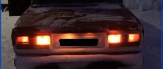
Accessories for modernizing rear lights
For such a mass model as the VAZ 2107, many small domestic and foreign companies produce many options for lighting equipment for tuning, which can be easily installed in standard places and do not require alteration of the body structure. Alternative taillights of the VAZ 2107 can be made using both incandescent lamps and LEDs. The latter are more expensive, but have a number of advantages:
- Less energy consumption. LEDs consume 10 times less energy than incandescent lamps of similar brightness.
- Fast response. Incandescent lamps do not light up immediately; they require time to warm up the coil, while LEDs begin to glow at full power immediately after voltage is applied.
- Higher information content of signals, achieved due to the original arrangement of light indicators.
- Increased brightness compared to standard devices.
Taillights for tuning the VAZ 2107 are presented on the market in a wide range. Conventionally, they can be divided into five groups:
- A sporty version featuring four round and two rectangular indicator lights. They can be arranged separately and placed in a plastic case, painted in the color of the car body.
- Skylain lights with three round indicators and two rectangular turn and brake indicators located above them. The lamp housings are made of transparent plastic with a chrome finish.
- The “eyelash” taillights are distinguished by their original shape and LED turn indicators, which are perfectly visible even in bright sunlight.
- Tinted rear lights designed specifically for those who love unusual lighting solutions. More powerful lamps installed in them ensure good visibility of signals even in bright light.
- LED lights of a classic design, the indicators in which are located similarly to the standard ones. They are popular due to their fast response and high signal brightness.
To install tuned taillights, it is enough to remove the standard taillights of the VAZ 2107 and install new ones in their place. The removal and installation procedure is described above, in the section “Tinting the rear lights of the VAZ 2107”.
Search principle
To find a fault in any vehicle on-board network system, you should use the method of sequential elimination of elements. The point is to consistently check electrical appliances and sections of the circuit, excluding elements from the list of reasons that could cause a breakdown. To do this, you need to clearly understand the design and operating principle of the system. When troubleshooting, you need to move from the components that require the least effort to check, to the most difficult to diagnose elements.
Electrical diagram
We immediately emphasize that the pinout of connectors and color markings of wires may differ not only between different models of the same automaker, but also among one model of different years of manufacture. Before you start searching for the cause of the breakdown, you need to find an electrical diagram specifically for your car model.
We will consider the principle of operation of brake lights and the troubleshooting algorithm using the example of the VAZ 2101-2102 circuit. The photo shows the general diagram of the vehicle's lighting and light signaling. We need to isolate the components involved in the operation of brake lights.
- 6 – mounting fuse block;
- 13 – brake light switch. It is a non-locking button (returns to its original position after removing the force). Located directly next to the brake pedal. When the brake pedal is released, the contacts of the limit switch are open, no current passes through it. Accordingly, when pressed, the contacts close, allowing flow through the lamps;
- 19 – lamps that light up when you press the brake pedal.
We do not have a diagram of the mounting block, but we know in advance that the brake lights only work when the ignition is on. There is a wire from the mounting block to the brake light limit switch, on which there is a constant + after the ignition is turned on. As soon as the limit switch contacts close, + goes to the brake light bulbs, which are connected in parallel. The “ground” of the rear lights is common and consists of a wire screwed to the car body.
In the diagram we presented, the elements are depicted as close as possible to how they look in reality. Don’t be alarmed if you only find a schematic diagram for your car with symbolic images of the elements. Schematic diagram of external lighting for VAZ 2114, 2115:
- 3 – mounting block;
- 8 – lamps for side lights and brake lights;
- 11 – brake light limit switch;
- K4 – relay for monitoring the serviceability of brake light lamps and side lights.
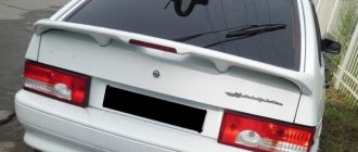
Tuning headlights VAZ-2107
With the help of tuning, you can achieve a more modern and stylish appearance for the VAZ-2107 headlights, give them exclusivity, and, in addition, improve their technical performance. Most often, LED modules assembled in various configurations, as well as glass tinting, are used for tuning. You can purchase ready-made modified headlights or do the conversion yourself. Among the most popular options for tuning headlights are the so-called angel eyes (LED modules with characteristic contours), eyelashes (special plastic covers), DRLs of various configurations, etc.
Video: black “angel eyes” for the “seven”
VAZ-2107 is one of the most respected domestic car brands by car owners. This attitude is due to a number of reasons, including reasonable price, adaptability to Russian conditions, availability of spare parts, etc. The driver can perform minor repairs on almost any vehicle system on his own, using a set of publicly available tools. All this fully applies to the lighting system and its main element - headlights, the repair and replacement of which, as a rule, does not cause any particular difficulties. When carrying out repair work, you must, however, adhere to certain rules so as not to damage or disable adjacent components and parts of the machine. Practice shows that careful and caring attitude towards lighting devices can guarantee their long service life.
What to do if there is no charge, weak charge (battery is discharged)?
If the battery of your VAZ 2107 is discharged, then one of three elements may be “to blame”: the generator, the voltage regulator, and the connections between them. Determining “who is to blame” can be very simple, even without additional devices. How this article will help.
We carry out testing using standard equipment
To monitor the operation of the generator on the “seven” there are two instruments: a voltmeter and a control light on the instrument panel. With their help, you can track the cause of your troubles.
1) Turn on the ignition without turning on the starter
and look at the warning light. It should shine at full intensity, as in the photo. The voltmeter needle, normally, stands on the white part of the scale (photo). Let's say everything is OK - go to point 2 - start the engine.
The battery charge control lamp is on
Position of the voltmeter needle before starting the engine (ignition on)
The lamp does not light, the voltmeter needle remains at zero when the ignition is turned on.
Check fuse No. 10 in the mounting block. 99% of the time it will be burnt out. In this case, all other lamps on the instrument panel will also be de-energized. Replace it with the same one and test again. If the fuse burns out again, you need to look for the cause, that is, a short circuit. We check whether the wires from the generator are disconnected, whether the insulation is frayed somewhere, etc. Diagram 3 at this link will help you find the reason
The lamp does not light up, the voltmeter needle shows normal
We check the wires on the generator to see if the wire has come loose from terminal “61”. If everything is normal there, you need to check whether there is a “plus” on this wire using a test lamp, an indicator screwdriver or a multimeter.
Terminal “61” of the VAZ-2107 generator
If there is a “plus”, we check the “tablet” (aka “chocolate”) and the generator.
There is no “plus” - you will have to remove the instrument panel and check the lamp. Replace the burnt out one. How to remove the panel, watch the video
2) Start the engine
The control lamp should go out, the voltmeter needle goes into the green sector and is located from the middle to the right edge (photo). If everything is so, then most likely the generator is working normally.
The voltmeter shows normal voltage (charging is present)
The lamp remains on or dims slightly
If you give it gas, it goes out at high speeds and lights up again when they decrease. The voltmeter needle is in the white sector and goes to the edge of the green when the speed increases. The generator output is faulty. The same conclusion if the lamp continues to light at any speed, and the voltmeter needle is in the white sector and even goes to red.
Voltage too low (motor running). Weak charge
Read, it may come in handy: If the electric motor of the heater (stove motor) of the VAZ-2107 does not work
Side lights VAZ 2107
The standard dimensions on the VAZ 2107 do not have bright light. Over the years, due to the wear and tear of the glass, even replacing the light bulbs in the headlights no longer helps. Therefore, it is quite logical that the car owner decides to tune the side lights.
On a VAZ 2107, tuning the dimensions comes down to transferring these lights from the sidelights to a separate lighting element on the body. This way they will be better visible, which will create comfortable and safe conditions for movement on the roads in any weather.
On old VAZs, tuning the side lights is considered a mandatory procedure.
Minor modifications will be required using the following tools:
- electric drill;
- mandrel;
- pliers or pliers;
- Phillips-blade screwdriver;
- side cutters.
Transferring the side lights from the sidelights to the body is impossible without the following materials:
- light bulb socket;
- new sidelights;
- wires for connection;
- terminals;
- new light bulbs (drivers recommend Philips Vision 12 V).
Transfer process
Any tuning requires accuracy and care. And carrying side lights is no exception. Here it is recommended to follow the rule “measure twice, cut once”:
- Measure the diameter of the hole in the car headlight.
- Drill a hole of the same diameter on the new lamp.
- Drilling should be done with drills of different diameters, gradually increasing the diameter so as not to damage the headlight glass.
- Prepare a landing site for the socket with a light bulb (try it on, if the socket does not fit, increase the drilling depth).
- Squeeze the cartridge and insert it into the socket. Using a mandrel, straighten it and fix it securely.
- Insert the light bulb into the socket.
- Connect the wiring to the new lamp and connect the lighting device according to the diagram.
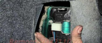
Removing and replacing rear lights
The procedure for replacing rear lights is as follows:
- First you need to turn off the ignition, open the hood and disconnect the terminals from the battery.
- Then open the trunk of the car and remove the protective cover on the headlight, disconnect the mount and disconnect the wiring connector from the contacts on the board. Be careful not to damage them.
- Using a size 8 socket wrench, you need to unscrew the four nuts that secure the taillight. Having done this, under the nuts of the studs you will be able to see the tips of the ground cable.
- Next, you need to carefully remove the taillight from its seat. To change the diffuser, it must be removed from the optics body.
- The procedure for installing and assembling optical elements is performed in reverse order.
Photo gallery “Changing headlights with your own hands”
Typical headlight malfunctions and methods for eliminating them
During operation, the car headlight is one way or another subject to mechanical damage and exposure to atmospheric factors, so after a certain period of operation it may require repair or restoration.
Glass replacement
To dismantle the VAZ-2107 headlight, you will need an 8-size open-end wrench and a Phillips screwdriver. The sequence of actions when removing the headlight is as follows:
- Under the hood, you should find the power plugs for the lamps and hydraulic corrector and disconnect them.
- On the front side of the headlight, you need to unscrew three bolts with a Phillips screwdriver.
- When unscrewing one of the bolts from the reverse side, you will need to secure the counter nut with a size 8 wrench.
- Remove the headlight from the niche.
The glass is attached to the headlight housing using sealant. If it is necessary to replace the glass, the joint should be cleaned of old sealant, degreased and a new sealing layer applied. Then attach the glass and secure it with masking tape. After 24 hours, the headlight can be replaced.
Video: replacing headlight glass on a VAZ-2107
Replacing lamps
To replace a burnt-out high-low beam lamp in a VAZ-2107 headlight, you must:
- Disconnect the negative battery terminal.
- Remove the headlight unit cover by turning it counterclockwise.
- Disconnect the power supply from the lamp.
- Remove the spring clip from the chuck grooves.
- Remove the lamp from the headlight unit.
- Install the new lamp in reverse order.
When carrying out work to replace lamps, you should remember that when we touch the lamp bulb with our hands, we oil it, and this can lead to premature failure of the lamp.
Replacing side light bulbs and direction indicators, as a rule, does not cause any difficulties: to do this, you need to remove the corresponding socket from the reflector and remove the lamp by rotating it counterclockwise.
Video: replacing the main and side lamps on a VAZ-2107
Glass cleaning
If the headlight glasses have lost their transparency, you can try to restore their appearance and light transmittance by contacting a service station specialist or performing the restoration of the optics yourself. To do this, the car owner will need:
- sandpaper of different grain sizes;
- abrasive and non-abrasive paste;
- masking tape;
- rags;
- grinding machine or grinder with a grinding wheel.
Glass restoration work is carried out in the following sequence:
- The headlight is covered around the perimeter with masking tape or film so that during work the paintwork of the body is not damaged.
- The surface of the glass is treated with sandpaper, starting with coarse sandpaper and ending with fine-grained sandpaper. If grinding is performed mechanically, the surface should be periodically moistened with water.
- The treated surface is thoroughly washed with water.
- The glass is polished with polish and washed again with water.
- The surface is alternately treated with abrasive and non-abrasive paste using a grinding machine with a foam wheel.
Methods for troubleshooting
Troubleshooting is not a complicated process and even novice car enthusiasts can do it (the author of the video is Avtoelektika VC).
Using a multimeter, you need to test the wiring. Damaged or torn sections should be replaced intact or soldered. If there are traces of oxidation processes on the contacts, they need to be cleaned.
If the LEDs burn out, they need to be replaced in pairs. If the breaker fails, it must be replaced with a new one, as it cannot be repaired. Before replacing, turn off the vehicle's power by removing the negative terminal from the battery. Then disconnect the power wires from the breaker. Next, you need to loosen the lock nut and unscrew the main nut securing the switch to the bracket.
Replacing the brake light switch
Before installation, the new frog should be checked for functionality. This can be done using an ohmmeter. We connect the device to the device and measure the resistance. When the contact is closed, the resistance should be zero. If you press the rod, the contacts should open; the resistance in this case tends to infinity.
Installation of xenon headlights on a VAZ 2107
Xenon headlights are characterized by a particularly powerful luminous flux, which requires additional focusing using lenses. Full-fledged xenon headlights are expensive and include, in addition to the power supply and lamps, an automatic beam height adjustment system and a headlight glass washer. Each of the elements is extremely important for safety:
- correct focusing and adjustment of the light flux is necessary so that oncoming drivers are not blinded by bright light;
- Without a washer, dirty headlight glass overheats and may burst.
If you do not have the funds to install xenon headlights of appropriate quality, it is better not to install fakes, endangering yourself and other road users, so we do not recommend installing this type of lighting and did not describe the connection