Greetings, dear friends! I decided to devote today’s post entirely to the ECU (Electronic Engine Control Unit) of the VAZ 2114. After reading the article to the end, you will learn the following: what ECU is on the VAZ 2114 and how to find out its firmware version. I will give step-by-step instructions for its pinout, tell you about the popular ECU models January 7.2 and Itelma, and also talk about common errors and malfunctions.
The ECU or Electronic Engine Control Unit of the VAZ 2114 is a unique device that can be described as the brain of a car. Absolutely everything in the car works through this unit - from a small sensor to the engine. And if the device starts to malfunction, then the machine will simply stop, because there is no one to command it, distribute the work of departments, and so on.
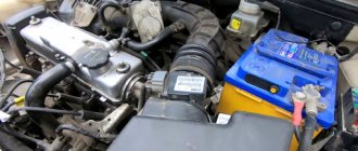
Where is the ECU located on the VAZ 2114
In a VAZ 2114 car, the control module is installed under the center console of the car, in particular, in the middle, behind the panel with the radio. To get to the controller, you need to unscrew the latches on the side frame of the console. As for the connection, in Samar modifications with a one and a half liter engine, the mass of the ECU is taken from the power unit housing, from the fastening of the plugs located to the right of the cylinder head.
Location of the VAZ 2114 ECU
In cars equipped with 1.6- and 1.5-liter engines with a new type of ECU, the mass is taken from the welded stud. The pin itself is fixed on the metal body of the control panel near the floor tunnel, not far from the ashtray. During production, VAZ engineers, as a rule, do not securely fix this pin, so over time it can become loose, which will lead to the inoperability of some devices.
Getting rid of the immobilizer in Lada-2114
Having connected a new alarm system, they often encounter one problem - the autostart does not work. You need to immediately check whether all connection points are used. In the latest VAZ models, such as 2114, the ignition switch contains three terminals: starter, power, ignition. It’s difficult to get confused here, but the engine can start and stop after 5 seconds. In reality, this is how standard protection works. How to deal with it is discussed further.
We are looking for the “culprit” of all problems
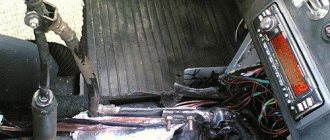
Let's assume that we are talking only about the VAZ-2114 hatchback. If the key, that is, the key fob, needs to be leaned against the platform, disconnect its two connectors (the light bulb and the antenna). And then, taking a screwdriver, you can dismantle the separate block attached to the right of the steering column:
The unit itself is called APS-4, but in its case, if we talk about the last years of production, APS-6 electronics may be located.
Let's say they are installing an alarm system with auto start, and a standard immobilizer, such as APS-6, has been activated. There are four solutions:
- An immobilizer bypass is connected to the alarm, and a chip key is placed inside the bypass body;
- A good option is to install keyless crawlers, only cars of the 2114 family do not have a CAN bus, and there is nowhere to connect digitally;
- You can also switch the immobilizer to service mode, but in APS-6 modules, unlike APS-4, this feature is blocked;
- Finally, you can get rid of the standard protection completely, but to do this you will need to reset the EEPROM of the ECU.
In general, EEPROM is a “storage device”, and the ECU is the engine controller. It turns out that you will have to work with the controller unit, but the immobilizer itself will remain the same.
How to find out which ECU is on the VAZ 2114 – January 7.2 January 4 Bosch M1.5.4
Today, there are 8 (eight) generations of electronic control units, which differ not only in characteristics, but also in manufacturers. Let's talk about them in a little more detail.
ECU January 7.2 – technical specifications
And so now we move on to the technical characteristics of the most popular ECU January 7.2
January 7.2 is a functional analogue of the Bosch M7.9.7 block, a “parallel” (or alternative, as you like) domestic development with M7.9.7. January 7.2 is externally similar to the M7.9.7 - assembled in a similar case and with the same connector, it can be used without any modifications on the Bosch M7.9.7 wiring using the same set of sensors and actuators.
The ECU uses a Siemens Infenion C-509 processor (the same as the ECU January 5, VS). The block’s software is a further development of the January 5 software, with improvements and additions (although this is a controversial issue) - for example, an algorithm has been implemented, literally an “anti-shock” function, designed to ensure smoothness when starting and shifting gears.
ECU January 7.2
The ECU is produced (хххх-1411020-82 (32), firmware begins with the letter “I”, for example, I203EK34) and “Avtel” (хххх-1411020-81 (31), firmware begins with the letter “A”, for example, A203EK34) . Both the blocks and the firmware of these blocks are completely interchangeable.
ECUs of series 31 (32) and 81 (82) are hardware compatible from top to bottom, that is, firmware for 8-cl. will work in a 16-cl. ECU, but vice versa - not, because the 8-cl. block “does not have enough” ignition keys. By adding 2 keys and 2 resistors you can “turn” an 8-cell. block of 16 cells. Recommended transistors: BTS2140-1B Infineon / IRGS14C40L IRF / ISL9V3040S3S Fairchild Semiconductor / STGB10NB37LZ STM / NGB8202NT4 ON Semiconductor.
Typical ECU parameters January 7.2 for diagnostics
ECU January-4 - technical specifications
The second serial family of ECMs on domestic cars was the “January-4” system, which was developed as a functional analogue of GM control units (with the ability to use the same composition of sensors and actuators in production) and was intended to replace them.
Therefore, during development, the overall and connecting dimensions, as well as the pinout of the connectors, were preserved. Naturally, the ISFI-2S and “January-4” blocks are interchangeable, but are completely different in circuit design and operating algorithms. “January-4” is intended for Russian standards; the oxygen sensor, catalyst and adsorber were excluded from the composition, and a CO adjustment potentiometer was introduced. The family includes control units “January-4” (a very small batch was produced) and “January-4.1” for 8 (2111) and 16 (2112) valve engines.
ECU January 4 second generation of electronic control unit VAZ 2114
The “Kvant” versions are most likely a development series with J4V13N12 firmware in hardware and, accordingly, in software, are incompatible with subsequent serial controllers. That is, the J4V13N12 firmware will not work in “non-quantum” ECUs and vice versa. Photo of KVANT ECU boards and a regular serial controller January 4
ECU diagram January 4
Features of the ECM: without neutralizer, oxygen sensor (lambda probe), with CO potentiometer (manual CO adjustment), toxicity standard R-83.
Bosch M1.5.4 – technical specifications
The next step was to develop, together with Bosch, an ECM based on the Motronic M1.5.4 system, which could be produced in Russia. Other air flow sensors (MAF) and resonant detonation sensors (developed and produced by Bosch) were used. The software and calibrations for these ECMs were first fully developed at AvtoVAZ.
For Euro-2 toxicity standards, new modifications of block M1.5.4 appear (has an unofficial index “N”, to create an artificial difference) 2111-1411020-60 and 2112-1411020-40, satisfying these standards and incorporating an oxygen sensor, catalytic neutralizer and adsorber.
The brains of the Bosch M1.5.4 ECU
Also, for Russian standards, an ECM was developed for 8-class. engine (2111-1411020-70), which is a modification of the very first ECM 2111-1411020. All modifications, except the very first, use a wideband knock sensor. This unit began to be produced in a new design - a lightweight, leak-proof stamped body with an embossed inscription “MOTRONIC” (popularly “tin can”). Subsequently, ECU 2112-1411020-40 also began to be produced in this design.
Replacing the structure, in my opinion, is completely unjustified - sealed blocks were more reliable. New modifications most likely have differences in the circuit diagram towards simplification, since the detonation channel in them works less correctly, the “tins” “ring” more when using the same software.
Itelma 5.1 - technical characteristics of the VAZ 2114 ECU
NPO Itelma has developed an ECU for use in VAZ cars, called VS 5.1. This is a fully functional analogue of the ECM January 5.1, that is, it uses the same harness, sensors and actuators.
VS5.1 uses the same Siemens Infenion C509, 16 MHz processor, but is made on a more modern element base. Modifications 2112-1411020-42 and 2111-1411020-62 are designed for Euro-2 standards and include an oxygen sensor, catalytic converter and adsorber; this family does not provide R-83 standards for 2112 engines. For 2111 and Russia-83 standards Only ECM version VS 5.1 1411020-72 with simultaneous injection is available.
Itelma 5.1 - technical characteristics of the VAZ 2114 ECU
Since September 2003, VAZ has been equipped with a new HARDWARE modification VS5.1, which is incompatible in software and hardware with the “old” one.
- 2111-1411020-72 with firmware V5V13K03 (V5V13L05). This software is incompatible with software and ECUs of earlier versions (V5V13I02, V5V13J02).
- 2111-1411020-62 with firmware V5V03L25. This software is not compatible with earlier versions of software and ECUs (V5V03K22).
- 2112-1411020-42 with firmware V5V05M30. This software is incompatible with software and ECUs of earlier versions (V5V05K17, V5V05L19).
In terms of wiring, the blocks are interchangeable, but only with their own software corresponding to the block.
Bosch M7.9.7 - ECU technical specifications
The 30 series Bosch was also found on 1.6 liter engines, but due to the initial development for a one and a half liter car, the software was very buggy, sometimes completely refusing to work. A special configuration marked 31h, released a little later, worked much more adequately.
The January seven had many models depending on the configuration and engine size, so on 1.5 liter eight-valve engines models produced by AVTEL were installed with the bar: 81 and 81h, the same brain from the manufacturer ITELMA had the numbers 82 and 82h. Bosch M7.9.7 was installed on 1.5-liter engines of export models and was marked 80 and 80h on Euro 2 cars and 30 on Euro 3 cars.
The brains of the Bosch M 7 ECU
1.6 liter engines of cars intended for the domestic market had on board devices from the same AVTEL and ITELMA. The first series from the first ones, marked 31, suffered from the same problems as Bosch 30 series, later all the shortcomings were taken into account and corrected in 31 hours. Despite problems among competitors, ITELMA has noticeably grown in the eyes of car enthusiasts, releasing a successful series number 32. Additionally, it should be noted that only Bosch M7.9.7 with marker 10 complied with the Euro 3 standard. The cost of a new ECU of this generation is 8 thousand rubles, used can be found at a disassembly site for 4 thousand.
For this we need:
Universal adapter KL-Line BM9213 USB MASTER KIT for tuning a car with an injection engine, you will not chip the carburetor with it,
You can read more about it and how to purchase it here. For the adapter, the driver for the virtual COM port for Win XP, Vista can be downloaded here, you can also use another adapter VAG COM USB KKL v409.1 which can be purchased from our partners, this is the one The KK-Line adapter is exclusively in the case and for funny means.
Next, for flashing the chip firmware, we will need ChipLoader 1.96; you can also use the newest version of ChipLoader 1.97.7, and the previous one works smoothly, so I don’t see the need to use the new one.
in the Help > Help tab you will find the User Guide, also go to options and uncheck all the boxes as shown in the figure above. In order for the block to start sewing, it needs to be modified according to the annotations in the User Manual
, everything is carefully described there.
ECU pinout diagram January 7.2 VAZ 2114
The VAZ 2114 controller often breaks down. The system has a self-diagnosis function - the ECU queries all components and issues a conclusion about their suitability for operation. If any element fails, the “Check Engine” lamp will light up on the dashboard.
ECU pinout diagram January 7.2
It is possible to find out which sensor or actuator has failed only with the help of special diagnostic equipment. Even with the help of the famous OBD-Scan ELM-327, loved by many for its ease of use, you can read all engine operating parameters, find the error, eliminate it and delete it from the memory of the VAZ 2114 ECU .
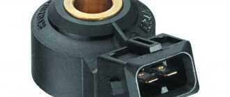
About the Hall effect
The essence of this effect is the emergence of a potential difference during the interaction of electric and magnetic fields. In this case, the electric field flows through the magnetic field, where the semiconductor wafer is located. It is at this point that the Hall voltage potential difference is formed.
In practice, the effect was applied as follows. When moving, the Hall voltage is converted into a pulse-frequency signal transmitted to the controller. The higher the speed, the higher the frequency of this signal becomes. From calculations it was possible to determine that the sensor produces 6004 pulses per 1 km of road. Due to the intervals between pulses, the sensor calculates the speed of the vehicle.
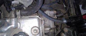
To perform any work with the DS, you first need to determine where it is located. The location of the speed sensor is the upper part of the gearbox housing. You can get to it through the engine compartment or from below if you park the car in a pit.
VAZ 2114 ECU burned out - what to do?
One of the common malfunctions of the ECU (electronic control unit) on the fourteenth is its failure or, as people say, combustion.
Obvious signs of this breakdown will be the following factors:
- Lack of control signals for injectors, fuel pump, valve or idle mechanism, etc.
- Lack of response to Lambda - regulation, crankshaft sensor, throttle valve, etc.
- Lack of communication with the diagnostic tool
- Physical damage.
In these cases, it is recommended to purchase a new ECU and replace the faulty one. How to do this is very simple!
How to remove and replace a faulty ECU on a VAZ 2114
When carrying out work to remove the VAZ 2114 ECU, do not touch the terminals with your hands. There is a possibility of damage to electronics due to electrostatic discharge.
- Using a screwdriver, unscrew the 3 screws securing the right panel of the instrument panel console and remove it.
- Release the clamp of the block with wires
- Disconnect the block from the ECU.
- Using a 10mm wrench, unscrew the 4 nuts securing the ECU to the bracket.
- We move the ECU forward and remove it from under the console.
- Remove the ECU from the bracket.
- Reinstall the ECU in reverse order.
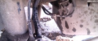
Where is the mass of the VAZ 2114 ECU located?
The first ground pin from the ECU on cars with a 1.5 engine is located under the instruments on the power steering shaft mount. The second terminal is located under the instrument panel, next to the heater motor, on the left side of the heater housing.
Location of the mass of the VAZ 2114 ECU
On cars with a 1.6 engine, the first terminal (mass of the VAZ 2114 ECU) is located inside the dashboard, on the left, above the relay/fuse block, under the sound insulation. The second terminal is located above the left screen of the center console of the instrument panel on a welded stud (fastened with an M6 nut).
Where is the relay and fuse of the VAZ 2114 ECU located?
The main part of the fuses and relays is located in the mounting block of the engine compartment, but the relay and fuse responsible for the electronic control unit of the VAZ 2114 are located in a different place.
Relays and fuses of the VAZ 2114 computer
The second “block” is located under the dashboard on the front passenger side. To access it you just need to unscrew a few fasteners using a Phillips screwdriver. Why is it in quotes, because there is no such block, there is an ECU (brains) and 3 fuses + 3 relays.
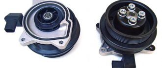
How to check the speed sensor
The most reliable way is a diagnostic scanner. You can contact a specialized service center and at the same time check the rest of the car’s systems. If you have a primitive error reader, such as the Chinese ELM 327, and a diagnostic program on your smartphone, this is quite enough. Scanner errors: P0500 or P0503.
In principle, owners of used VAZ cars should install an advanced on-board computer that can diagnose such faults.
Finally, the easiest way is a multimeter. To perform the check, you need to know where the speed detection sensor is located on the VAZ 2114.
You don't have to climb into a hole to access the device. In the area of the inner CV joint of the right wheel, under the throttle valve, you can see a wire going to the gearbox. It will lead us to the desired sensor.
- First you need to remove the connector and check the integrity of the wiring and cleanliness of the contacts. We clean off the corrosion with fine sandpaper and resolder the broken wire.
- Raise one of the front wheels with a jack, the gearshift lever is in neutral. We connect the tester probes to pins 2 and 3 in kOhm measurement mode. By turning the wheel, you can cause the sensor resistance to change within 3–10 kOhm.
- You can remove the sensor and check it using the so-called bench method. To do this, you need to supply power to it and connect the multimeter to the negative and signal connectors. We put a tube on the sensor shaft and rotate it as quickly as possible. The device readings (voltage) should change in time with the rotation.
- When rotating the shaft by hand, there should be no biting, the force is small and uniform. If the shaft rotates tightly, there is a mechanical failure inside.
What to do if the scanner does not see the VAZ 2114 ECU
Reader question: Guys, why does it say during diagnostics that there is no connection with the ECU? What to do? What to fix?
So, why doesn’t the scanner see the VAZ 2114 ECU? What should I do so that the device can connect and see the block? Today you can find many different adapters for testing a vehicle on sale.
If you buy an ELM327 Bluetooth, most likely you are trying to connect a low-quality device. Or rather, you could have purchased an adapter with an outdated version of the software.
Car diagnostics using a scanner
So, for what reasons does the device refuse to connect to the block:
- The adapter itself is of poor quality. Problems can be with both the device’s firmware and its hardware. If the main microcircuit is inoperative, it will be impossible to diagnose the engine operation, as well as connect to the computer.
- Bad connection cable. The cable may be broken or inoperative itself.
- The wrong version of the software is installed on the device, as a result of which it will not be possible to achieve synchronization (the author of the video about testing the device is Rus Radarov).
In this case, if you are the owner of a device with the correct firmware version 1.5, where all six of the six protocols are present, but the adapter does not connect to the ECU, there is a way out. You can connect to the unit using initialization strings, which allow the device to adapt to the commands of the machine’s motor control unit. In particular, we are talking about initialization lines for diagnostic utilities HobDrive and Torque for vehicles that use non-standard connection protocols.
We flash the Itelma M74 (Lada Granta) ECU with our own hands
In order to independently flash the Itelma M74 ECU, which, as we already know, is installed on the Lada Grant, you need to perform the following procedure:
- Disconnect the battery mass.
- Remove the ECU block. The connectors are disconnected like this:
- Let’s make a “spider” like this (I recommend signing the wires)
- We connect the connectors: Connector 1 (large) J1 - switchable voltage (K15) (12V) - second switch B2 - programming permission (12V) - first switch A4 - programming permission (12V) - first switch Connector 2 (Small) G2;G3; G4 - Ground (can be connected to any) H1; H2 - non-switchable voltage (K30) F2 - switchable voltage (K15) (12V) - second switch D2 - K-Line
- here's EL. diagram (many people write that they are flashing, but there is no diagram anywhere)
6. It is not recommended to apply voltage to all wires at the same time! It is necessary step by step through a double switch.
7. 4-And so the whole circuit is assembled and the KKL VAG-COM cord is inserted into the USB PC. Here is the voltage supply sequence
- Apply voltage (+12 V) to H1; H2 (throw the hooks onto the battery)
- Turn on the first switch (programming permission) B2 A4
- We launch the WinFlashECU program (-Select M74, -select the port number on which KKL VAG-COM hangs -it’s better to set the speed to the minimum)
- Next, turn on the second switch (which is on the “switch-off voltage”) F2 J1
- Communication with the ECU should appear (this is an indicator that the circuit is assembled correctly)
- Then we save copies of your “firmware and immo” on your computer, click
- Reading EEPROM and Reading ECU just in case (at the same time we check how everything works)
- code copying finished
- click ECU programming, look for the required firmware on your computer and download
Voltage disappears on the VAZ 2114 ECU - what to do
Reader question: Hello everyone, please help me with the problem. The symptoms are as follows: 1. Error 1206 appears - on-board network voltage interruption. In cold weather, starting the engine is generally a problem - it takes a few seconds, a click sounds like a relay is triggered, the speed jump check light comes on and the car stalls. This can go on for half an hour, and the car may stall while driving. When the engine warms up, the loss stops. Where can I look for the cause of what kind of sensor might have gone missing? Thanks in advance!
Error voltage loss VAZ 2114
In principle, there can be many solutions to this problem:
- If the voltage on the battery is less than 12.4 volts, then the ECU begins to save energy, at 11 you may not even be able to start it on a cord))) The ECU sometimes sees a voltage less than what is actually on the battery, this usually indicates that it’s time to clean the ECU mass, Look into the connector and wipe the contacts. In your case, when it’s cold it’s a problem, when it’s hot everything’s fine. And if you look from the battery side? When hooked, the problem is, when recharged, everything is fine. A good diagnostician will not harm the machine
- I also recommend paying attention to the malfunction: ignition coil, ignition module, contactless spark plug ignition switch.
Well, that’s it, dear friends, our article about the VAZ 2114 ECU has come to an end. Still have questions? Be sure to ask them in the comments!