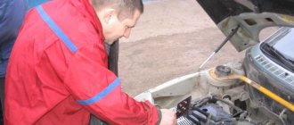
Hello subscribers and random visitors)))
Here I present to you my small problem. The car was not used for a long time, moved from place to place and, if absolutely necessary, no more than 60 km))))
I have long noticed poor engine starting after the car has been idle for a long time. When starting, the engine began to work first at 2x, then at 3x, and only after some time and at 4x after re-gassing and re-gassing)))) I periodically changed the spark plugs to start the engine.
I didn’t bother at that moment))) I was driving a Lada 2112 Car Wife - Auto Wife).
But then spring came and my beloved wife began to ask me: how soon will it move to 2112))))
And from that moment I decided to work on 2108 and began to resolve the issue of starting the engine.
Source www.drive2.ru
Lambda can, of course, choke. But then there would be a mistake. And 11 compr. It’s not enough for such a mileage and you probably need to turn it longer? And it’s strange that it’s so equally low, check the keys for everything. happening. Fuel pressure is accurate - OK?
There was a similar case. For stupidity, turning the ignition off and on helped. And there were also no “misfires” to be seen. They made the head. The 8-valve heads are obscenely made. Pay special attention to valve guides.
How did you determine that the force impulses disappear?
Source injectorcar.ru
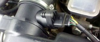
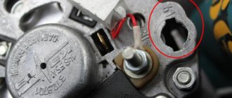
Checking the voltage supply to the fuel injectors
Location of the electrical connector (1) supplying voltage to the fuel injector and connector (2) on the fuel injector
PERFORMANCE ORDER 1. Disconnect the electrical connector from the fuel injector of the first cylinder, see fig. Location of the electrical connector (1) supplying voltage to the fuel injector and connector (2) on the fuel injector. 2. Connect the control LED to the connector contacts (1) (see Fig. Location of the electrical connector (1) supplying voltage to the fuel injector and connector (2) on the fuel injector). When the engine cranks with the starter, the LED should flash. 3. Check the voltage supply to the remaining fuel injectors in the same way.
The LED does not blink on any of the cylinders
Location of contacts on the electrical connector supplying voltage to the fuel injector
PERFORMANCE ORDER 1. Connect the control LED to contact No. 1 of the electrical connector to supply voltage to the fuel injector and vehicle ground, see fig. Location of contacts on the electrical connector supplying voltage to the fuel injector. 2. Connect pin No. 2 of the electrical connector to vehicle ground. 3. Turn the engine crankshaft with the starter. In this case, the LED should blink. Otherwise, check the entire electrical circuit supplying the fuel injectors.
LED does not flash on only one or more cylinders
PERFORMANCE ORDER 1. Check the condition of the electrical circuit powering the fuel injectors and determine and eliminate the location of the electrical circuit break or short circuit to ground. 2. Check the operation of the engine control unit.
Connection points for an ohmmeter to check the resistance of fuel injectors
PERFORMANCE ORDER Sequentially disconnect the electrical connectors from the fuel injectors and, using an ohmmeter, check the resistance of the fuel injectors, which should be in the range from 12 to 17 Ohms, see fig. Connection points for an ohmmeter to check the resistance of fuel injectors.
Warning When the engine is warmed up to normal operating temperature, the resistance of the fuel injectors increases by 4–6 ohms.
If the fuel injector resistance is not as specified, replace the fuel injector.
The fuel injector is an integral part of the vehicle's injection system. Naturally, the quality of the car as a whole depends on the proper operation of the injectors. Although engine compartment problems should be handled by a trained professional, you can determine the source of the problem yourself.
Lada 2108 Autostudio NCS › Logbook › NOZZLES ARE POURING INTO THE CYLINDERS.
Hello subscribers and random visitors)))
Here I present to you my small problem. The car was not used for a long time, moved from place to place and, if absolutely necessary, no more than 60 km))))
I have long noticed poor engine starting after the car has been idle for a long time. When starting, the engine began to work first at 2x, then at 3x, and only after some time and at 4x after re-gassing and re-gassing)))) I periodically changed the spark plugs to start the engine.
I didn’t bother at that moment))) I was driving a Lada 2112 Car Wife - Auto Wife).
But then spring came and my beloved wife began to ask me: how soon will it move to 2112))))
And from that moment I decided to work on 2108 and began to resolve the issue of starting the engine.
It is obvious that there is a RICH air-fuel mixture. Previously, I had an entry about spark plugs in the BZ: SPARK PLUGS - DETERMINING THE MALFUNCTION.
I carried out diagnostics on the car, the mass air flow sensor is in a state of very bad condition - it needs to be changed.
HAVE BUT!
The spark plugs are very wet before the engine starts. I decided to conduct an experiment.
The conclusion suggests itself - THE INJECTORS ARE NOT CORRECTIVE
I dismantled the fuel rail, reconnected it to the fuel path, pumped up the pressure, turning the ignition on and off: I LOOK AT THE
INJECTORS - THE INJECTORS ARE WET, one more than the other less ((((
I drove it, the car doesn’t stall, it responds well to the gas pedal. I calmed down and put the car in boxing and went to bed)))) as always, stayed until NIGHT)))
Thank you for your attention)))) Feel free to comment)))))
Possible malfunctions: causes, manifestations, consequences
Naturally, fuel injectors require periodic inspection and cleaning, and, if necessary, even replacement. Problems can be identified by a number of symptoms, including:
- The appearance of uncharacteristic failures when starting the power unit and when it is idling;
- Increased consumption;
- Uncharacteristic exhaust color.
After the first manifestations of the problem, we can talk about the presence of sulfur deposits on the system elements, corrosion, wear of filters and some working parts. As a result of the influence of each process, the fuel mixture supply system becomes clogged, and, consequently, a loss of power and high consumption.
The instruction manual states that the injectors must be cleaned every 20–30 thousand kilometers. In practice, this interval is reduced to 10–15 thousand km.
The injector is pouring into the cylinder: causes and solutions to the problem
Issues discussed in the material:
The fuel system of the car has changed significantly since its invention. A modern car can consume less fuel by smoothly adjusting the speed thanks to the dosed supply of the mixture. The engine injectors that make up the injection system are responsible for this function. This technology replaced the classic carburetor design, surpassing the latter in all respects. However, the injector is also susceptible to breakdowns. In particular, sometimes a situation arises when the injector pours into the engine cylinder. Why does this happen and how to deal with it? This will be discussed in this article.
Checking power supply to injectors
If the driver notes that all injectors are working properly, but when the ignition is turned on, the injector refuses to work, then it makes sense to check the pulse supply to the injectors.
To properly check, you need to disconnect the block from the injector and prepare two wires for connecting them to the battery. The second contacts are connected to the injectors.
Then, after preparation is completed, the ignition is turned on and fuel leakage analysis is carried out. The main task is to record the presence or absence of a leak. As a result, if fuel leaks, then we can talk about problems in the operation of the entire electrical circuit. If no leakage is observed, then the system is working properly.
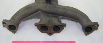
Design and principle of operation
The main function of the fuel supply system is to inject fuel in certain doses under pressure.
There are two main types of nozzles:
In a standard diesel injector, the atomizer is the main part. It can have several holes, be adjusted in different ways and supply diesel fuel. For example, simple diesel power units are equipped with elements with a single-hole atomizer and a needle. But GDI engines are equipped with nozzles with many holes, usually from 2 to 6.
You can imagine the normal operation of injectors like this. Diesel fuel flows from the tank to the fuel injection pump under low pressure. Then the fuel injection pump sequentially pumps fuel under strong pressure to the injection elements. They open under pressure. As soon as the pressure drops, the diesel injection is also switched off.
Electrically controlled injectors are created as a result of the progress of diesel fuel systems. Here, diesel fuel is supplied to the cylinders according to the same principle, only the nozzles do not open under pressure. An electromagnetic valve controls this entire process. It is not on its own, but is controlled directly by the car's ECU. Without a corresponding signal from there, fuel does not enter the atomizer.
Electromechanical control has many advantages. Thus, in Common Rail diesel injectors, up to 7 injections can occur in one cycle, which a priori increases engine power. Thanks to high-precision distribution in such systems, the combustible mixture is uniformly dosed, atomized and burned more efficiently.
Pump-injector systems have also recently become popular. There is no fuel injection pump; each cylinder has its own nozzle.
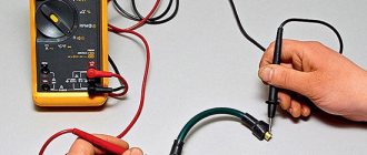
Measuring resistance using a multimeter
One of the main methods used to determine fuel injector failures is to measure resistance using a multimeter. Before starting work, it is important to determine the factory impedance of the TF.
When diagnosing, the ignition must be turned off and the negative terminal from the battery disconnected. The corresponding electrical connector on the injector is disconnected. This can be done using a screwdriver with a fairly thin end - the clamp on the block snaps off.
The multimeter must be switched to ohmmeter mode and the corresponding contacts must be connected. The results obtained between the center and outer contacts should fall in the range of 11-17 ohms for high impedance injectors or in the range of 2-5 ohms for low impedance injectors.
The presence of any deviations from the norm provides grounds for a more detailed diagnosis. In some cases, the fuel injector is replaced with a known good one in order to evaluate the operation of the power unit.
Frequently asked questions about auto diagnostics via a computer or smartphone Logan and Logan 2
OBD2 adapters and scanners allow you to read and decipher most codes and view sensor readings in real time.
Renault Logan engine and sensor diagnostics via OBD2
Through the OBD2 interface you can perform diagnostics and read parameters from engine sensors:
- Lambda probe
- Speed sensor
- Coolant temperature sensor
- Idle speed sensor
- Air conditioner pressure sensor
- Throttle sensor.
- Air flow sensor.
Other sensors:
- Engine temperature – transmits information to the ECU about the need to turn on the fan.
- Exhaust air temperatures - check before cold start.
- Detonation - normal readings: 03-1 Volts.
- ABS and SRS sensors
For a detailed look at the sensors and engine management system EMS 31-32, please read the documentation below:
Siemens (EMS 31-32 controller) (.PDF)
Suitable adapters for Logan diagnostics
Adapters with an ELM327 microcontroller that support ISO 14230 or 9141-2 protocols are used. They can connect via Wi-Fi or Bluetooth.
For car enthusiasts, it is recommended to use the universal OBD2 Scan Tool Pro with firmware v. 1.5.
The adapters require an external receiver in the form of a laptop or smartphone with diagnostic software installed, such as Torque Pro or OBD Car Doctor software.
Suitable scanners for diagnosing a Renault Logan car
- Original car scanners: for Renault Logan 1 and 2, from 2004 to the present - State DST-2, State DST-mini.
- Universal car scanners: Launch CReader VI+, Launch X431 Pro– for cars with OBD2 support.
- Dealer diagnostic device for Renault cars since 1990 - Renault CAN Clip.
Is it possible to diagnose suspension, steering and chassis via OBD2?
Mechanics, such as the chassis, cannot be checked with this scanner. If sensors are installed in the systems, then readings and errors will be displayed, for example, such as the ABS sensor, sensors in the gearbox, etc.
Checking the injector balance
To balance the fuel pump, you must first turn off the fuel pump and start the car. After a few seconds of operation, the engine should stall - this is necessary to eliminate excess pressure of the mixture. Then the pressure gauge is connected, and only after that the fuel pump returns to its place. Next, a computer with the necessary software is connected and diagnostics are carried out.
Subsequent actions are performed exclusively using specialized programs. You may notice that the fuel pump will gradually turn on and off, as will the injectors. In general, the following algorithm can be distinguished:
- Turning on the ignition;
- Pressure gauge readings are in the range of 2.8–3 atm;
- The fuel pump turns off;
- Pressure drop to 2.5–2.8 atm;
- Checking one TF;
- Analysis of pressure gauge data – significant dynamics should not be observed;
- The pressure is restored to its original value by turning on the fuel pump;
- The procedure is repeated one by one with all nozzles.
When working correctly, each element will give approximately the same performance. If the reset is different in a certain place, then we can talk about a malfunction of the injector or its further diagnostics. After completing the manipulations, the pressure gauge must be turned off only after first releasing the pressure in the system.
VAZ-2110 diagram for an injector with 8 valves - applicability for repairs
Now more and more motorists are trying to replace the carburetor on their VAZ-2110 with an injector, which has a number of significant advantages. It allows the valves in the engine to work much more efficiently, reducing the load on the engine and the average fuel consumption in the car. At the same time, it is simply impossible to install an injector without a diagram, even if you are a professional car service worker.
Contents: 1 Why is the VAZ-2110 electrical circuit needed? 2 The main elements of an injector with 8 and 16 valves and their functions 3 How to adjust the fuel supply process using an electrical circuit? 4 How does the controller monitor the operation of the injector? 5 How does a malfunction of the electronic control unit affect the operation of the injector?
Why is the VAZ-2110 electrical circuit needed?
When replacing or repairing an injector with 8 valves, the electrical diagram serves as a kind of guide, with the help of which you can understand all the nuances in the process of connecting specific wiring parts. In addition, the VAZ-2110 electrical diagram when using an injector with 8 valves allows you to understand the functioning of all electrical wiring devices.
In the diagram, the injector valves are evenly spaced, while the system itself is presented in the form of two combined components:
- Fuel distributor;
- Electrical equipment for the ignition control system.
Also, the diagram with 8 and 16 valves indicates the location of the electronic unit, with the help of which the operation of the above two systems is coordinated. Backup equipment, in turn, protects electrical wiring from overloads and increases the operating efficiency of the entire injection system.
Advice: if you are going to repair the injector, be sure to look at the wiring diagram for the VAZ-2106. This will give you the opportunity to replace any faulty parts without affecting the overall functioning of the vehicle's wiring.
The elements indicated by numbers in the diagram are shown below:
| 1 - block headlight | 35 — instrument lighting switch |
| 2 — front brake pad wear sensors | 36 - ignition switch |
| 3 - reverse light switch | 37 — mounting block |
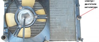
| 4 — electric motor of the engine cooling system fan | 38 - recirculation valve switch |
| 5 - sound signal | 39 - heater controller |
| 6 — gear motor for locking the lock of the right front door | 40 - hazard switch |
| 7 - relay for turning on electric windows | 41 — lamp for illuminating the heater control levers |
| 8 - 8 A fuse | 42 — glove box lighting lamp |
| 9 - starter | 43 - glove compartment lamp switch |
| 10 - battery | 44 - cigarette lighter |
| 11 - generator | 45 — display unit of the on-board control system |
| 12 - windshield washer motor | 46 — ashtray lighting lamp |
| 13 — washer fluid level sensor | 47 - brake light switch |
| 14 — gear motor for locking the left front door lock | 48 — gear motor for locking the left rear door lock |
| 15 — left front door power window switch | 49 - left rear door power window switch |
| 16 - coolant level sensor | 50 — electric window motor reducer of the left rear door |
| 17 - windshield wiper gearmotor | 51 - socket for a portable lamp |
| 18 — recirculation valve | 52 - hours |
| 19 — micromotor gearbox for heater damper drive | 53 — electric window motor reducer of the right rear door |
| 20 — heater electric motor | 54 - right rear door power window switch |
| 21 — trunk lock switch | 55 — gear motor for locking the right rear door |
| 22 — right front door power window switch | 56 - side turn signal |
| 23 — electric window motor reducer of the right front door | 57 - parking brake warning lamp switch |
| 24 - control unit for door lock system | 58 - driver's seat belt sensor |
| 25 - additional resistor of the heater electric motor | 59 — directional lamp |
| 26 — brake fluid level sensor | 60 — interior lamp |
| 27 — electric window motor reducer of the left front door | 61 — cabin air temperature sensor |
| 28 — external lighting switch | 62 — switch in the front door pillar |
| 29 - instrument cluster | 63 — switch in the rear door pillar |
| 30 - rear fog light switch | 64 — external rear light |
| 31 - fog light indicator lamp | 65 — internal rear light |
| 32 - indicator lamp for heated rear window | 66 — license plate lights |
| 33 - rear window heating switch | 67 — trunk light |
| 34 — steering column switch |
The diagram of electrical wires and fuses gives an understanding of the entire operation of the injection system, and also shows the specific position of each of the elements. It contains the following elements:
- Central nozzle. Acts as a distributor of fuel supply to the system. There is also a special type of fuel regulator that works as a sensor and ensures that the fuel supply does not go beyond the normal limits.
- Diaphragm regulator. Monitors fuel pressure in the ignition system and removes excess fuel back into the tank body.
Advice: make sure that the pressure in the fuel supply system does not exceed 300 MPa. Otherwise, you will see the corresponding icon on the instrument panel and you will most likely have to replace the coolant on the VAZ-2110.
- Bypass valve design. It regulates the position of the cross diaphragm, which is subject to constant pressure from three sides: on one side, the pressure of the fuel itself, on the other side, the tangential load from the intake air volumes, and on the 3rd side, the tension from the spring attached to the valve.
How to adjust the fuel supply process using an electrical circuit?
According to the scheme described above, fuel regulation in a car is carried out. Moreover, it depends not only on the load of the valves in the engine, but also on the corresponding position relative to the throttle valve. With the help of a diagram of electrical wiring and valves, it is possible to understand which of the relays or fuses is malfunctioning and replace it in time. In this case, one of the main roles when supplying fuel is played by electrical equipment (controllers) that regulates the operation of the injector.
How does the controller monitor the operation of the injector?
When determining the specific position and opening time of the injector design, the specific volume of fuel entering the valves of the VAZ-2110 cylinder is determined. At the same time, thanks to special sensors installed on the motor, the on-board computer records specific values and transmits them to the controller.
Subsequently, the controller, based on the information coming from the on-board computer, makes a decision on the position and duration of opening of the injector damper. If the controller malfunctions, the injectors will not be adjusted correctly, and the engine may stall while driving.
Tip: when starting the engine, the injector controller operates in asynchronous mode until the engine reaches a certain number of revolutions. That is why, after replacing the silent blocks of the front control arms on a VAZ-2110, you should warm up the car for 10-15 minutes.
How to clean injectors without removing them from the engine?
Usually, the most common problem with TFs is their improper or untimely cleaning, as a result of which they become clogged. There are three types of cleaning:
To clean the injectors without removing them, it is usually enough to select and pour a chemical composition into the fuel tank that can normalize operation. From time to time it is recommended to accelerate the engine to high speeds and speeds of 110–140 km/h on flat sections of the road. When covering a distance of 10–25 km in this mode, the system undergoes “self-cleaning” under load.
However, such methods are effective only for minor stains. Large lesions must be removed using ultrasound or high pressure. And in order to prevent this, it is necessary to wash the fuel filter every 40–50 thousand kilometers.
You can visually familiarize yourself with the technique of checking injectors with your own hands in the video:
Simple instructions with photos and video examples on how to independently check injectors on VAZ 2113, 2114, 2115 cars.
To carry out work on checking the injectors you will need: A wire 2 meters long, electrical tape, a multimeter.
- Remove the decorative trim from the 1.6 engine.
Disconnect the injector wiring harness connectors.- Turn on the ignition and use a voltmeter to measure the voltage at terminal E of the wiring harness block. The voltage must be at least 12V.
- After taking measurements, turn off the ignition. If, as a result of measurements, it turns out that there is no voltage on the block or it is less than 12V, then you need to check the battery charge, the power circuit and the serviceability of the computer.
- We check the electrical resistance of the injectors, for which we use an ohmmeter to alternately measure the resistance between terminal E and the other four terminals of the block (2). The block terminal marked with the letter B corresponds to the injector of the first cylinder, and terminals C, G and F correspond, respectively, to the injectors of the second, third and fourth cylinders. For serviceable injectors, the resistance should be 13 ohms.
- When performing the following operation, do not apply voltage more than 12 V to the terminals of the block, and after performing the test, do not leave the terminals under voltage, as this may lead to burnout of the injector windings.
- Using two wires directly from the battery, we briefly apply 12 V voltage to the terminals of the block (2) - connect terminal E to the positive terminal of the battery, and terminals B, C, G and F in series with the negative terminal of the battery. For a working injector, a characteristic click should be heard when the valve opens.
- We replace faulty injectors.
Cleaning
There are two ways to clean fuel nozzles, each of which has its own nuances. Choose for yourself which one you like best or is more affordable, taking into account the available funds.
| Cleaning method | Necessary materials | Features of the event |
| First way | You will need:
|
|
| Method two | You will need:
|
|
Both operations take approximately 2-3 hours, but cost several hundred rubles. This is ten times cheaper than replacement and about the same amount more affordable than service stations.
After cleaning the injectors, check their operation. If this does not work, you will have to change it.
Source
Diagnostic parameters for standard ECU
| Parameter | Name | Unit/composition | Ignition | (XX 800 rpm) | XX (3000 rpm) |
| TMOT | Coolant temperature | °C | -1 | 90°-105° | 90°-105° |
| TANS | Intake air temperature | °C | -1 | -20°…+50° | -20°…+50° |
| UB | On-board voltage | IN | 11,8–12,5 | 13,2 – 14,6 | 13,2 – 14,6 |
| WDKWA | Throttle position | % | 0 | 0 | 2–6 |
| NMOT | Knee rotation frequency. shaft | rpm | -1 | 800 +/‐40 | 3000 |
| M.L. | Mass air flow | kg/hour | -1 | 7–12* | 24–30* |
| 8–13 | 26–34 | ||||
| ZWOUT | Ignition timing | grd. p.k.v. | -1 | 7–17 | 22–30 |
| R.L. | Load parameter | % | -1 | 18–24 | 14–18 |
| FHO | Altitude adaptation factor | -1 | 0,7–1,03** | 0,7–1,03** | |
| T.I. | Injection pulse duration | msec | -1 | 3,5–4,3 | 3,2–4,0 |
| MOMPOS | Current position of the IAC | step | -1 | 40 +/‐15 | 90 +/‐15 |
| DMDVAD | XX adjustment adaptation parameter | % | -1 | +/‐5 | +/‐5 |
| USVK | Oxygen sensor signal | IN | 0,45 | 0,05–0,9 | 0,05–0,9 |
| FR | Injection time correction coefficient based on DC signal | -1 | 1 +/-0,2 | 1 +/-0,2 | |
| TATEOUT | Fill factor of the adsorber purge signal | % | -1 | 0–15 | 90–100 |
| LUMS | Uneven rotation of the knees. shaft | r/sec^2 | -1 | 0…5 | 0…10 |
| FZABG | Counter of misfires affecting toxicity | -1 | 0 | 0 | |
| VSKS | Instant fuel consumption | l/hour | -1 | -1 | -1 |
| FRA | Multiplicative component of self-learning correction | 1 +/-0,2 | 1 +/-0,2** | 1 +/-0,2** | |
| RKAT | Additive component of self-learning correction | % | -1 | +/‐5 | +/‐5 |
| B_LL | Sign of engine operation in XX mode | NOT REALLY | NO | YES | NO |
| B_KR | Knock control active | NOT REALLY | -1 | YES | YES |
| B_LR | Sign of engine operation in the control zone based on the DC signal | NOT REALLY | -1 | YES | YES |
| B_LUSTOP | Misfire detection suspended | NOT REALLY | -1 | NO | NO |
* These parameters can be viewed through the Dialogys 4.74 program.
Have you done computer diagnostics yourself?
Ilya Vasiliev Site author / Diagnostician
I publish articles with reviews of diagnostic equipment, share my experience, programs and instructions.