In technical and structural terms, a car is a rather complex means of transportation. The components and mechanical parts and systems included in it must work harmoniously and properly. If one unit is damaged and any part malfunctions, a significant deviation in the functionality of the vehicle or its breakdown may occur. Among most important car structures, the ignition system is considered one of the most significant. It significantly affects the possibility of uninterrupted operation of the car. Today we know about three types of ignition systems that can be installed on a car: contact, non-contact and microprocessor. The latter is considered the newest achievement in the automotive industry. This useful material will take a closer look at contactless and contact systems and describe their differences.
What is the difference between contact and contactless ignition systems?
In technical and structural terms, a car is a rather complex means of transportation. The components and mechanical parts and systems included in it must work harmoniously and properly. If one unit is damaged and any part malfunctions, a significant deviation in the functionality of the vehicle or its breakdown may occur. Among most important car structures, the ignition system is considered one of the most significant. It significantly affects the possibility of uninterrupted operation of the car. Today we know about three types of ignition systems that can be installed on a car: contact, non-contact and microprocessor. The latter is considered the newest achievement in the automotive industry. This useful material will take a closer look at contactless and contact systems and describe their differences.
Setting the ignition timing
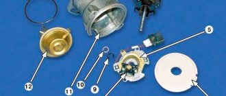
After we have studied the distributor device on the VAZ 2109, we move on to adjusting the ignition timing. To complete this job you will need:
- Crooked starter or ratchet wrench
- The slotted (flat) screwdriver is durable and has a powerful, wide blade
- Set of probes
- Open-end wrench “12x13”
- Conical rubber plug
- A spark plug wrench or a suitable socket with a wrench instead
Preparing for adjustment
In order for the engine of your car to work as expected, it is necessary that a spark jumps at the right time, which would ignite the mixture by the time the piston passes TDC and the gas, having completed the work of expansion, pushes the piston down. To ensure that the spark occurs on time, the ignition system uses a distributor, the main components of which are a contact group and a slider. The most important adjustments for cam ignition are: the gaps between the cams, the angles of the closed state of the contacts (UZSK) and the ignition timing. Before you start setting the ignition timing with your own hands, you need to make sure that:
- The spark plugs are in good condition and suitable for further use.
- If they have oil deposits on them, then it is recommended to calcinate them.
- It is not recommended to use sandpaper for cleaning, even fine sandpaper; fine abrasive from it may remain on the ceramic insulator and, as a result, the spark plug will begin to pierce
- It is not at all necessary to ignite the candles red hot, the main thing is to burn off the oil deposits
- Then we will adjust the gaps of all spark plugs in accordance with the manual
- To do this, use a wire probe
- We definitely check the condition of the contacts of our breaker
- If there are signs of metal burnout or signs of corrosion, replace the contacts
- It is not recommended to repair them, for one simple reason: after repair, the contacts will not last long! It’s easier to replace them and forget them for a long time
- We check the capacitor using a tester for charge and discharge
- The current should flow smoothly and slowly
- To do this, it is better to use a pointer tester, it can be seen more clearly
- You need to make sure there is good contact in the main wire coming from the ignition coil.
- By the way, it doesn’t hurt to check it either
- You can also check with a tester, megger, or the easiest way and completely free of charge at a good auto parts store on the stand
- We remove dirt from the ignition coil, distributor cap and distributor
- If carbon deposits have formed on the distributor cap, it must be replaced.
- Don’t save money, take a branded factory cover, the price will be paid off by the quality
- We carefully assess the condition of the carburetor
- If the carburetor does not respond to adjustment, it is time for repair. But this is a separate article
- Checking the operation of the vacuum ignition timing
- So that its drive runs without jamming, and the tube is thick-walled without cracks or breaks
We insert the breaker-distributor itself
Having made sure that all elements of the system are in good working order, we proceed to the adjustment, first consider the situation when the distributor was removed entirely:
- Now, in order to insert it into place, you need to select one of the 1st or 4th cylinders in which the piston moves in the compression stroke at TDC when the marks of the crankshaft pulley and the front cover are aligned
- This is done simply. We take a rubber cone plug, unscrew the spark plug of the first cylinder, insert the plug into the spark plug hole, tighten it
- Smoothly rotate the crankshaft with a crooked starter or ratchet wrench
- As soon as the desired (the first in our case) cylinder comes to TDC, a rubber plug comes out of it
- I advise you to immediately tie the cork so that you can look for it for a long time later
- Now we combine the marks on the pulley and the front cover (with the longest one)
- Then we insert the distributor strictly along the slots so that the slider stands evenly and perpendicular to the plane of the engine head and looks at it
- Then we raise the distributor a little bit to make it possible to rotate the shaft and not catch the splines, and rearrange it clockwise by one tooth
- We do this to give the distributor the fullest possible stroke for adjustment.
Direct adjustment
Adjustment instructions when the distributor is in place:
- It is necessary to set the gap between the contacts, strictly according to the car manual
- For classics this gap is 0.45
- Angles of the closed state are set only on special testers, so you don’t need to set them yourself, it just won’t work
- We connect all the wires as expected and set the torque adjustment in the middle of the stroke
- Then insert the spark plug of the 1st cylinder into the spark plug wire corresponding to the first cylinder and turn on the ignition
- Rotate the pulley counterclockwise about 45 degrees
- Then we create ground contact for the spark plug and smoothly rotate the pulley in a clockwise direction
- As soon as a spark jumps between the electrodes, stop rotating the crankshaft
- Checking the marks (on the cover and pulley)
- If there is a run-up between them, you need to turn the distributor one to two degrees in the required direction
- When the pulley mark runs forward from the front cover mark in the direction of rotation, it means that the ignition is late and the distributor should be turned counterclockwise
- When the mark, on the contrary, does not reach the mark on the cover, it means that the ignition is early and the distributor should be turned clockwise
- Next, we repeat the previous procedure with rotating the pulley back and again catch the moment the spark jumps, compare the marks and adjust
- With some experience everything will turn out quickly and easily
Advice: the more carefully and slowly you rotate the pulley, the more accurately you will be able to set the ignition
- When we have reached an exact match of the marks, tighten the distributor and turn the crankshaft two full turns, then check the adjustment again
- When a run-up appears, eliminate it; if everything matches, start the engine and warm up
- Next, we accelerate the car to a speed of 40-50 kilometers per hour, and engage fourth gear, then sharply press the gas
- If you suddenly hear the sound of valves busting, then the ignition should be set later
- Typically, fine adjustments do not require further adjustments.
Quick method
A faster method is suitable for starting the engine for the first time after repair:
- Install the distributor in place according to the principle described above
- It’s easier to set the advance torque
- Having found the TDC of the piston of the 4th cylinder, we combine the crankshaft mark with the middle mark on the cover
- Then we turn the distributor slowly clockwise and counterclockwise, as soon as a spark jumps, we stop and fix the distributor
- Ignition set
We set the advance using the strobe light
There is a way to adjust the ignition using a strobe light. It is the simplest and most accurate, but depends on the serviceability of the device. All stroboscopes are different in design, however, they all have the same operating principle:
- We connect the wires supplying the strobe to the terminals, and the wire that receives the pulses to the spark plug cap without removing it
- The setting is performed at idle speed
- Point the strobe light at the hole (hatch) in the clutch housing (see)
- It is better to mark the mark on the crankshaft flywheel with a bright white marker or corrector
- We point a strobe light at the pulley and, under the influence of flashes emitted by the strobe light with a certain frequency, we see the marked mark stationary
- Rotate the distributor in the required direction until the required marks coincide and fix it
Warning: If the mark under the strobe beams moves back and forth, this indicates a malfunction of the ignition system (usually the capacitor or contacts).
Now that the adjustment is complete, a video on this issue will clarify all unclear points.
The saying that new is not the best is not always true. If we talk about ignition systems, it does not apply here. The old, proven over the years, cam (contact) ignition system has already been forgotten, as it has been replaced by a contactless one, which is not only newer, but also more practical, more efficient, and more reliable. But what are the advantages of each system? This is something worth understanding in more detail and making a final conclusion about which is better.
Contact ignition system: what is special?
The contact ignition system is a classic mechanism that contains a power supply, an ignition switch or switch, as well as a coil, spark plugs, a special timing mechanism and insulated high-voltage wiring. The power source is the battery in the car starting mode, and the generator directly in the engine operating mode. The ignition switch allows you to supply energy to the on-board network and the starter relay, but the ignition coil is designed to accumulate and convert voltage to form a charge between the electrodes. A special feature of the contact ignition system is that it has so-called “cams”, which are driven by torsion of the distributor shaft drive. This system is considered simpler, has a simple configuration and is reliable. The system does not provide for the use of complex design solutions such as modern block electrical systems.
Contact ignition
Contact ignition system is the most authentic type of ignition. Its advantages include high reliability, low cost, ease of maintenance and maintainability, even in field conditions.
Currently no longer fitted to production vehicles, it has been replaced by a newer contactless system as its performance is much better. However, debate continues among owners of older cars about which type is better, so many cars continue to use a system that uses the contact principle of operation.
The contact ignition system has one big drawback - the contacts themselves, which tend to heat up and also burn out during long-term and continuous operation. In addition, while the contacts are closed, voltage loss occurs, which leads to battery discharge and heating of the coil, even when the engine is not running.
Non-contact type ignition: features
In a non-contact ignition system, instead of a vulnerable mechanical contact current interrupter, a special non-contact type sensor is provided. In its design, such ignition is similar to contact ignition, but it provides for the modernization of a pulse sensor and a transistor-type switch. The sensor in the contactless ignition system organizes low-voltage electric pulse activity. By type, sensors are divided into elements of induction and optical type, as well as using the Hall effect. In this system, the current interrupter in the primary winding of the coil is a transistor-type switch, which responds to signals supplied by the sensor. As for breaking the current supply, this process occurs by opening and closing the transistor output element.
More details about the contactless ignition system are discussed in this video:
Source
BSZ structure
The contactless ignition system is a number of different mechanisms, namely:
- Ignition switch;
- Pulse sensor;
- Transistor switch;
- Ignition coil;
- Spark plug;
- Sensor-distributor (distributor);
- High and low voltage wires.
The structure of the contactless ignition system can be clearly seen in the photo; we will briefly analyze the principle of its operation.
As you probably already understood, the entire system is based on a Hall sensor, which, acting on the semiconductor with a magnetic field, creates a transverse voltage. This happens due to the slot design of the device, that is, a semiconductor (and a permanent magnet) is located on opposite sides of the hole.
A steel cylinder with slots rotates in the slot itself. Thus, when the sensor slot and the cylinder slots coincide, the magnetic flux acts on the conductor (through which, by the way, current flows when the ignition is on), then the resulting pulses act on the switch, after which they are converted into the current of the primary winding of the ignition coil.
Types of ignition systems
Let us remember once again that the ignition system is a set of all instruments and devices that ensure the appearance of a spark at a moment corresponding to the order and mode of operation of the engine. This system is part of the overall electrical system.
Ignition systems can be divided into 3 groups:
1 - Contact ignition systems - includes a mechanical breaker and the creation of high voltage and its distribution among the cylinders in this system occurs using contacts. In a contact ignition system, the accumulation and distribution of electrical energy among the cylinders is controlled by a mechanical device - a switch-distributor. A further development of the contact ignition system is the contact transistor ignition system, in which a transistor switch is used in the primary circuit of the ignition coil.
2 - Non-contact ignition systems - includes a non-contact sensor, which replaced the contact breaker. The use of a non-contact ignition system allows you to increase engine power, reduce fuel consumption and emissions of harmful substances due to a higher discharge voltage (30,000V) and, accordingly, better combustion of the fuel-air mixture. Unlike a contact system, a contactless ignition system uses a transistor switch that interacts with a contactless pulse sensor to control energy accumulation. The transistor switch in this system acts as a breaker. The distribution of high voltage current is carried out by a mechanical distributor.
3 - Electronic ignition system (microprocessor ignition system) - a system in which the creation and distribution of high voltage current across the engine cylinders is carried out using electronic devices. The electronic ignition system has no mechanical contacts. The electronic ignition system uses an electronic control unit, which controls the process of accumulation and distribution of electrical energy. In early electronic ignition system designs, the electronic unit simultaneously controlled the ignition system and the fuel injection system (the so-called combined injection and ignition system). Currently, ignition control is included in the engine management system.
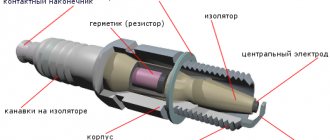
All of the above types of ignition systems are similar to each other, they differ only in the method of creating a control pulse. So the ignition system includes: The power source for the ignition system is the battery (at the time the engine starts) and the generator (while the engine is running). The ignition switch is a mechanical or electrical contact device that supplies voltage to the ignition system, or in other words, the ignition switch. As a rule, it performs two functions: supplying voltage to the on-board network and ignition system, supplying voltage to the vehicle starter solenoid relay. Energy accumulator - a unit designed to accumulate and convert energy sufficient to cause an electrical discharge between the electrodes of the spark plug. Conventionally, energy storage devices can be divided into inductive and capacitive. The simplest inductive accumulator is an ignition coil, which is an autotransformer; its primary winding is connected to the positive pole and through an interruption device to the negative one. During operation of a breaking device, such as an ignition cam, a self-induction voltage arises in the primary winding. An increased voltage is generated in the secondary winding, sufficient to breakdown the air gap of the spark plug. A capacitive storage device is a container that is charged with increased voltage and at the right moment transfers its energy to the spark plug. Spark plugs are a device with two electrodes located at a distance of 0.15-0.25 mm from each other. This is a porcelain insulator mounted on a metal thread. In the center there is a central conductor, which serves as an electrode, the second electrode is the thread. The ignition distribution system is designed to supply energy from the accumulator to the spark plugs at the right moment. The system includes a distributor and/or switch, and an ignition system control unit. Ignition distributor (distributor) is a device for distributing high voltage along the wires leading to the cylinder spark plugs. Usually the distributor also contains a cam mechanism. Ignition distribution can be mechanical or static. The mechanical distributor is a shaft that is driven by the engine and, using a “runner,” distributes the voltage along high-voltage wires. Static ignition distribution implies the absence of rotating parts. With this option, the ignition coil is connected directly to the spark plug, and control comes from the ignition control unit. If, for example, a car engine has four cylinders, then there will be four coils. There are no high-voltage wires in this system. The switch is an electronic device for generating control pulses for the ignition coil; it is connected to the power circuit of the primary winding of the coil and, upon a signal from the control unit, interrupts the power supply, resulting in a self-induction voltage. The ignition system control unit is a microprocessor device that determines the moment at which an impulse is sent to the ignition coil, depending on the data from the crankshaft position sensors, lambda probes, temperature sensors and the camshaft position sensor. A high-voltage wire is a single-core wire with increased insulation. The inner conductor can be in the shape of a spiral to eliminate interference in the radio range.
Source
Advantages of BSZ
The task of the ignition system is to provide the ignition spark with sufficient energy at the right moment to ignite the fuel mixture.
The more accurately this process is performed, the greater the engine's power and efficiency. Correctly set ignition allows you to increase engine power, reduce fuel consumption and emissions of harmful substances. In recent years and decades, these goals have become increasingly relevant. The contact ignition system could not cope with the demands placed on it. The maximum transmitted energy required to ignite the working mixture could not be increased, although this was necessary for engines with high compression and power, the rotation speed of which became increasingly higher.
In addition, due to constant wear of the contacts, it is not possible to ensure exact compliance with the specified ignition moment. This caused interruptions in engine operation, increased fuel consumption and emissions of harmful substances into the atmosphere.
Thanks to the development of electronics, it was possible to initiate the ignition process without contact, thereby solving wear and maintenance problems. In this case, the specified ignition timing is precisely maintained throughout almost the entire service life.
First of all, this is achieved thanks to inductive signal formation (contactless transistor ignition system with energy storage in inductance) and signal formation by a Hall sensor (TSZ-h).
Because both of these systems are economical and relatively inexpensive, they are still used today on some small engines.
The main advantages of a contactless ignition system:
- no wear or maintenance,
- constant ignition moment,
- absence of contact bounce and, as a consequence, the possibility of increasing the rotation speed,
- regulation of energy storage and limitation of primary current,
- higher secondary voltage of the ignition system
- DC switch off.
Electronic ignition connection diagrams: VAZ 2101-VAZ 2107
Scheme of a contactless ignition system for VAZ cars:
How contactless ignition works
The sequence and principle of operation of the BSZ is as follows:
ECMs are sometimes interchangeable, but sometimes they are not repairable.
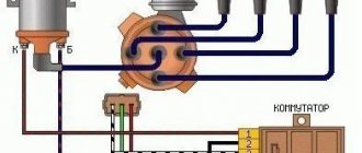
Diagram of an outdated VAZ ignition system (without switch)
1 — distributor (distributor);
2 - breaker; 3 - capacitor; 4 — ignition coil (bobbin); 5 - battery; 6 — ignition switch; 7 - spark plugs. This scheme is in systems where there is no switch. The circuit is broken mechanically using a breaker.
Disadvantages of contact ignition:
Disadvantages of contactless ignition:
Scheme and principle of operation of BSZ
All elements of the system are connected to each other and to the engine as follows:
- The distributor shaft rotates from the motor drive gear;
- The Hall sensor installed inside the distributor is connected to the switch;
- the coil is connected by a low voltage line to the controller, a high voltage line to the central electrode of the distributor cover;
- high-voltage wires from the spark plugs are connected to the side contacts of the main distributor cap.
The threaded clamp “K” on the coil is connected to the positive contact of the ignition switch relay and terminal “4” of the switch. The second clamp marked “K” is connected to contact “1” of the controller, and the tachometer wire also comes here. Terminals “3”, “5” and “6” of the switch are used to connect a Hall sensor.
Selection of BSZ
When purchasing a new BSZ, you should pay attention to the presence of the components of the entire kit. The factory kit should contain:
In appearance, the BSZ kit for the VAZ 2121 NIVA is very similar. But it’s better not to install this kit on a VAZ 2107 or a VAZ 2106, because the characteristics of the “six” and “seven” are very different from the “Niva”. Distributor brands for Niva: 3810.3706 or 38.3706–10.
The best manufacturer of electronic ignition systems for old VAZ cars is. The production capacity base is located in the city of Stary Oskol. According to reviews from car owners of classic BSZ SOATE models, this is an excellent option.
Complete non-contact ignition system
Naturally, you won’t be able to get all the benefits of the BSZ by installing only a sensor-interrupter. This module only improves the reliability of sparking (without skipping) and relieves owners from the need to constantly monitor the condition of the mechanical contact group. In order to equip your car with a full-fledged BSZ, you need to purchase a kit consisting of:
- distributor, with installed Hall sensor;
- semiconductor switch;
- high voltage coil;
- connecting wires with installed blocks.
Such a set for classic VAZ cars from SOATE (Russia, Stary Oskol) currently costs about 2,500 rubles. The video below describes in detail the process of installing it yourself:
Installation of contactless ignition for VAZ 2107, 2106
To install the BSZ with your own hands, you will need the following tools:
An inspection hole for installing the ignition is not required. Here, in fact, is the procedure for removing the old contact ignition:
The procedure for installing contactless electronic ignition on a VAZ 2106-2107.
After installation in the correct sequence, we start the engine and begin setting up the ignition. If after installing a new electronic contactless ignition the engine does not start, you should check the correct connection of the coil wires and the high-voltage wires to the spark plugs. If the wires are normal, then the marks are not aligned.
Ignition adjustment
At home, you can set the ignition timing “by ear”, setting the timing so that in this position the speed of the warmed-up engine is the highest and most even. When driving at a speed of 50 km/h in fourth gear, when the gas pedal is fully pressed, a “knock” sound should occur until the speed increases by 3-5 km/h. If the sound is heard longer, the advance angle must be reduced.
In a car service center, ignition adjustment is carried out using specialized equipment.
Installation of electronic ignition on video for classic VAZ 2101-2107 cars.
This video covers all the nuances.
How to adjust contactless ignition
Before setting the ignition on VAZ 2101-2107 cars, you need to warm up the engine a little, without letting it stall.
You can adjust either by ear or using a special device called a strobe to set the ignition.
A strobe light is a device with which even a beginner can set the ignition correctly. For more information on setting up the ignition with a strobe, watch the video.
Source
A budget option for switching to a contactless system
The contacts of the mechanical breaker “burn out” and wear out, so they have to be periodically cleaned and the gap adjusted. Installing the Sonar IR module (costing 700÷900 rubles) in the distributor allows owners of classic VAZs (2101-2107) to be spared from this routine work.
The device consists of:
- optical sensor (infrared radiation source and photodetector);
- electrical signal amplifier;
- switching transistor.
Important! All of the above is mounted in a miniature waterproof housing, which makes it quite easy to install it in place of a standard contact breaker.
The operating principle of the module is as follows:
- When the distributor rotor rotates, its cams periodically block the light flux of the optical sensor.
- Electrical impulses from the photodetector are amplified by a built-in microcircuit and supplied to a control transistor, which opens/closes the circuit of the primary winding of the coil.
On a note! LED indicators (red and green) inform about the state of the electronic switching key (closed/open).
How to install and configure Sonar IR is described in detail in the video below:
What is the difference between a non-contact contact distributor and an electronic one?
Modern contactless distributor and coil
The modern contactless ignition system or BSZ is an advanced and constructive solution, a kind of continuation of the old contact-transistor system. Here the usual fuse contact is replaced by a special and efficient regulator. How else do these two systems differ? Let's find out.
KSZ is the first, already outdated, ignition option that is still used on rare cars. In the KSZ, the current and its segregation are carried out by a distributor using a contact group.
The KSZ includes such components as a mechanical distributor and a mechanical interrupter, an ignition coil, a vacuum sensor, etc.
Mechanical interrupter or circuit breaker
Contact ignition system circuit
This is the component that is responsible for disconnecting the low current section. In other words, the current generated in the primary winding. The voltage goes to the contact group, the elements of which are protected from burning by a special coating. In addition, there is a condenser-heat exchanger connected simultaneously to the contact group.
The ignition coil in the KSZ is a current converter. This is where low voltage current is transformed into high current. As in the case of BSZ, two types of windings are used.
Mechanical distributor or just distributor
This component is capable of efficiently supplying high current to the SZ. The distributor itself consists of many elements, but the main ones are the cover and the rotor or slider (people).
The cover is made so that on the inside it is equipped with connectors of the main and additional types. The high current is received by the central contact, and is distributed over the spark plugs - through the side (additional) ones.
The mechanical interrupter and distribution are a single tandem, just like the hall sensor with the switch in the BSZ. They are driven by the crankshaft drive. In common parlance, both elements are called the single word “distributor”.
TsROZ is a regulator used to change the SOP depending on the number of revolutions of the crankshaft of the power plant. A priori, it consists of 2 weights acting on the plate.
Setting up OZ
In other words, the UOZ is the angle of rotation of the crankshaft, such that direct transmission of high-voltage current to the SZ occurs. In order for the combustible mixture to burn without residue, ignition is advanced.
The OZ in the KSZ is set using a special device.
VROZ or vacuum sensor
It provides a change in SOP depending on the load on the motor. In other words, this indicator is a direct consequence of the degree of throttle opening, which depends on the force of pressing the accelerator pedal. The VROZ is located behind the throttle valve and is capable of changing the SOP.
Armored wires are mandatory elements, a kind of communications that serve to transmit high-voltage current to the distributor and from the latter to the spark plugs.
The functioning of the KSZ is carried out as follows.
Vacuum regulator distributor
The contact-transistor ignition system is a further modernization of the old KSZ. The difference is that the switch is now used. As a result, the service life of the contact group has increased.
Coil
In the KSZ, one of the mandatory, important elements is the coil. It includes a line of very significant components such as windings, tube, resistor, core, etc.
The difference between low-voltage and high-voltage windings lies not only in the nature of the voltage. The primary winding has fewer turns than the secondary winding. The difference can be very large. For example, 400 and 25,000 turns, but the size of these same turns will be several times smaller.
Structure and functions of BSZ
Based on the figure, the operating principle of the system is briefly explained:
Drawing. Components of a transistor ignition system
- Accumulator battery
- Ignition and starter switch
- Ignition coil
- Switch
- Ignition sensor
- Sensor-distributor
- Spark plug
When the ignition (2) is turned on, supply voltage is supplied to the primary winding of the ignition coil (3). Current flows through the primary winding; as soon as the commutator (4) receives a signal from the ignition sensor (5), the current in the primary winding is interrupted. Terminal 1 of the ignition coil is connected to ground via a switch. A high voltage of more than 20 kV is induced in the secondary winding.
The secondary voltage of the ignition system is transmitted through terminal 4 of the ignition coil to the distributor sensor to the corresponding cylinder and spark plug.
The control unit determines the crankshaft rotation speed (sensor signals) and, based on it, controls the accumulation time of the current of the primary winding of the ignition coil (the duration of the open state of the output transistor or thyristor of the ignition system) and its magnitude. In accordance with the speed and voltage of the battery, shortly before the appearance of the ignition spark, the set value of the primary current is set, that is, as the speed increases, the duration of the current flow increases in the same way as when the battery voltage decreases.
When the ignition is turned on and the engine is not running (no sensor signal), after a while (usually after one second), the current in the primary winding of the ignition coil is turned off. As soon as the control unit receives a sensor signal (for example, during startup), it returns to operating status.
To adapt the ignition timing to different load conditions, adjustment is carried out in the same way as in contact ignition systems, mechanically through a membrane mechanism of a vacuum regulator, as well as a centrifugal regulator. As a result, the sensor signal (and with it the ignition timing) changes depending on the engine speed and load.
Drawing. Interaction diagram of vacuum and centrifugal adjustment when controlling the ignition using an inductive sensor
- Centrifugal regulator
- Vacuum ignition timing regulator with membrane mechanism
- Ignition distributor shaft 4 - Hollow shaft
- Ignition distributor inductive sensor stator
- Control pulse sensor rotor
- Ignition distributor rotor
Inductive signal formation in a contactless transistor ignition system by storing energy in inductance
As a result of rotation of the rotor of the control pulse sensor, the magnetic field changes and an alternating voltage shown in Figure a, b is created in the induction winding (stator). In this case, the voltage increases as the rotor teeth approach the stator teeth. The positive half-cycle of the voltage reaches its maximum value when the distance between the stator and rotor teeth is minimal. As the distance increases, the magnetic flux sharply changes its direction and the voltage becomes negative.
Drawing. Control pulse sensor based on the induction principle a) Process diagram
- Permanent magnet
- Core induction winding
- Variable air gap
- Control pulse sensor rotor
b) time characteristic of alternating voltage induced by the control pulse sensor tz = ignition timing
At this point in time (tz), as a result of interruption of the primary current by the commutator, the ignition process is initiated.
The number of rotor and stator teeth in most cases corresponds to the number of cylinders. In this case, the rotor rotates at a reduced crankshaft speed. Peak voltage (± U) at low speed is approx. 0.5 V, at high - approx. up to 100 V.
The ignition timing can only be monitored when the engine is running, since without rotation of the rotor the magnetic field does not change and, as a result, no signal is created.
What elements does the BSZ consist of?
BSZ is a modernized transformation of KSZ. In it, the mechanical breaker is replaced by a sensor. Today, most domestic models and foreign cars are equipped with such ignition.
Note. The BSZ can act as an additional element of the KSZ or function completely autonomously.
The use of BSZ allows one to significantly increase the power parameters of the power plant. It is especially important that fuel consumption is reduced, as well as CO2 emissions.
Ignition coil BSZ
In a word, the BSZ includes a number of components, among which a special place is occupied by a switch, pulse regulator, switch, etc.
BSZ is a device that is similar to a contact ignition system, but has a number of positive aspects. However, according to some experts, it is not without its drawbacks.
Let's look at the main elements of the BSZ to get a more overview.
Hall Sensor
Pulse regulator or DEI* - this component is designed to create low voltage electrical pulses. In the modern technology industry, it is customary to use 3 types of DEI, but in the automotive industry only one of them has found widespread use - the Hall sensor.
As you know, Hall is a brilliant scientist who was the first to come up with the idea of rationally and effectively using a magnetic field.
This type of regulator consists of a magnet, a semiconductor plate with a chip, and a shutter with recesses that actually transmit the magnetic field.
Note. The shutter has slots, but in addition to this, there is also a steel screen. The latter does not sift anything, and thus an alternation is created.
DEI – electrical impulse sensor
Hall Sensor
The regulator is structurally connected to the distributor, thereby creating a device of a single type - a regulator-distributor, outwardly similar in many functions to a breaker. For example, both have a similar crankshaft drive.
A transistor-type switch (CTS) is a useful component that serves to interrupt electricity in the ignition coil circuit. Of course, CTT functions in accordance with DEI, forming together with the latter a single and practical tandem. The electrical charge is interrupted by unlocking/closing the output transistor.
Coil
And in the BSZ the coil performs the same functions as in the KSZ. There are certainly differences (detailed below). In addition, an electrical switch is used here to interrupt the circuit.
The BSZ coil is more reliable and better in every way. The start-up of the power plant is improved, and the operation of the engine in different modes becomes more effective.
How does BSZ work?
The rotation of the crankshaft of the power plant affects the distributor-regulator tandem. In this way, voltage pulses are generated and transmitted to the CHP. The latter creates a current in the ignition coil.
Note. You should know that in auto electrics it is customary to talk about two types of windings: primary (low) and secondary (high). A current pulse is created in low voltage, and high voltage is created in high voltage.
BSZ functioning diagram
Next, high voltage is transmitted from the coil to the distributor. In the distributor it is received by the central contact, from which the current is transmitted through all armored wires to the spark plugs. The latter ignite the combustible mixture, and the internal combustion engine starts.
As soon as the crankshaft speed increases, the CROS* regulates the SOP**. And if the load on the power plant changes, then the vacuum sensor is responsible for the OZ.
TsROZ – centrifugal ignition timing regulator
UOZ – ignition timing angle
Of course, the distributor itself, be it old or new, is a mandatory element of the car’s ignition system, contributing to the appearance of high-quality sparking.
The new model distributor eliminates all the shortcomings of the contact distributor. True, a new one costs an order of magnitude more, but it usually pays off later.
As was written above, when operating the BSZ, a new distributor is used that does not have a contact group. Here the role of a breaker and connector is performed by a CCT and a Hall sensor.
The ignition system, in which the distribution of high voltage across the engine cylinders is carried out using electrical devices, is called ESZ. In some cases, this system is also called “microprocessor-based”.
Note that both previous systems - KSZ and BSZ also included some elements of electrical devices, but ESZ does not imply the use of any mechanical components at all. In essence, this is the same BSZ, only more modernized.
Electronic ignition system
On modern cars, the ESZ is an essential part of the internal combustion engine control system. And on newer cars, released more recently, the ESZ works in a group with the exhaust, intake and cooling systems.
There are many models of such systems today. These are the world-famous Bosch Motronic, Simos, Magnetic Marelli, and less famous analogues.
There are also differences between the coils. Both systems have different markings and different ignition coils. So, the BSZ coil has more turns. In addition, the BSZ coil is considered more reliable and powerful.
Thus, we found out that today there are 3 ignition options in use. Accordingly, different distributors are used.
Source
Replacing old with new
Many people, faced with problems caused by the contact ignition system, prefer to improve it or replace it altogether, but lovers of classic cars and car restorers prefer to keep the original. And this procedure is quite expensive - although the replacement work is quite simple and consists mainly of replacing parts and assembly, the kit itself is expensive.
The non-contact type is better than the contact type in that it is devoid of contacts, which often burn during prolonged use.
Unlike contact, contactless has a switch - this device replaces contacts, but performs the same functions. This is, in fact, the only difference between these ignition systems.
Differences between contact and non-contact ignition systems, advantages and disadvantages of each option
A car is a structurally and technically complex means of transportation, consisting of units, parts and systems that work in regular interaction. Damage or failure of any mechanism entails significant deviations in the functionality of the vehicle, and sometimes even complete breakdown of the car. One of the important designs that affects the possibility of uninterrupted operation is positioned by professionals as the vehicle ignition system. Most car owners know that it is directly responsible for supplying a spark category discharge to the spark plugs with specific sensitivity to the rhythm of the engine’s functioning. As technological progress progresses, history includes three types of ignitions installed on cars: contact, non-contact and the newest microprocessor-class ignitions. In this article, we will look at the differences between contact and non-contact systems that are installed on domestic cars and some foreign-made vehicles, and we will talk about the operating features, structure and advantages of second-generation systems.
Selecting the ignition type: contact or contactless.
And lastly
It should also be noted that the non-contact type has better current characteristics - higher frequency and voltage, which significantly extends the life of the spark plugs. However, this difference also has its drawbacks - you will have to replace standard high-voltage wires with silicone ones, which conduct current better, but are much more expensive.
VAZ 2107 cars use two types of ignition: an outdated contact system and a modern contactless system. The latter type began to be used on VAZ classics relatively recently, mainly on models equipped with injection engines. However, the advantages of the contactless circuit are fully realized on VAZ carburetor engines.
Contact category ignition systems
The classical mechanism, despite its technical obsolescence and concessions in characteristics to new systems, represents an extremely complex structure. The system consists of the following elements:
The fundamental feature of the functioning of the contact system is the activity of the so-called “cams”, driven by torsion of the distributor shaft drive. By disconnecting the cams, they interrupt the twelve volt supply to the outer winding of the bobbin. When the transformer loses voltage, electromotive induction is formed in the primary winding, which provokes the formation in the internal winding of a voltage of three thousand units necessary for the operation of the system. The high-voltage voltage is generated mechanically by a distributor, from where it is supplied alternately to the spark plugs through a battery or generator, changing with the rhythm of the engine. Voltage is generated in a sufficient volume for the occurrence of a spark discharge capable of breaking through the air gap between the electrodes of the spark plugs, which is a necessary aspect for igniting the working, fuel fluid.
Professionals consider the advantages of contact-type ignition to be its simplicity, which initially determines the reliability and simplicity of the configuration. The system does not involve complex design solutions of electronic class, in the form of modern block electrical systems, which are characterized by malfunctions and high commodity costs. The cam system also has certain disadvantages, since otherwise there would be no need for its structural improvement and modernization. The main disadvantage of the cam configuration is the formation of a spark: during the process of splitting the cams, carbon deposits appear on the metal contacts over time, which reduces the quality of contact, which results in problems with starting the engine. Carbon formation provokes the need for regular monitoring of the gap on the spark plugs, their cleaning and more frequent replacement for the correct functioning of the system.
Design and operating features of non-contact type ignition
Professionals position the non-contact ignition system - BSZ - as a technological improvement of the contact-transistor design, where instead of a vulnerable mechanical contact current interrupter, a special non-contact type sensor is installed. The design structure of the BSZ is similar to the previous variation, with modernization with a pulse sensor and a transistor-type switch. To understand how a contactless ignition system copes with the accumulation, conversion and distribution of voltage, it is necessary to understand the principle of interaction between the switch and the pulse sensor, which structurally distinguish the concept of the devices. The sensor procedurally implements the function of organizing low-voltage electric pulse activity. By type, sensors are divided into optical and induction class elements, as well as the most common converters that operate using the Hall effect, which consists in the formation of a diametrical potential difference in a conductor plate under the influence of a stable magnetic force. The pulse sensor in combination with the distributor is visually similar to a mechanical distributor and operates from the crankshaft drive of the internal combustion engine.
The current interrupter in the primary electrical winding of the coil is a switch of a transistor modification, responding to signals supplied by the sensor. Breaking the current supply process is accomplished by opening and closing the transistor output element. The operating principle of the contactless ignition system, taking into account the modernized elements, is based on the generation and transmission of signals by the sensor to the switch while the crankshaft of the power unit is running. The commutator generates electric current pulses in the outer turn winding. After the current is interrupted, the logical continuation of the process is the induction of high voltage voltage on the secondary electrical winding of the bobbin. Next, the process of transmitting voltage to the operating elements of the distributor, identical to the contact functioning of the system, occurs, followed by its distribution through the electrical wires to the spark plugs. The spark plugs, in turn, directly ignite the working fluid.
Differences between KSZ and BSZ
The question of which ignition is better, contact or contactless, is popular among owners of domestic vehicles, since professionals often position the possibility of replacing analog contact ignition with an improved contactless ignition. Each of the variations has both advantages and disadvantages, which forces car owners to weigh the differences between the systems, determining the priority of each of them. If we analyze the characteristics of the contact system, then its benefits are evidenced by the qualities of reliability and ease of maintenance, and the relatively low cost of structural elements. The non-contact design is a more modern solution, requires less adjustment, and is distinguished by the absence of vulnerable contacts, which are prone to burning during operation. Let's try to analyze in detail how to distinguish visually and in terms of parameters contact ignition from non-contact ignition, focusing on the main components of the systems that determine the difference. The problematic elements were replaced by a switch that performs the tasks of contacting structural parts, without the accompanying formation of carbon deposits, due to the absence of the need for direct mechanical contact during operation. The next thing that fundamentally distinguishes a contact system from a non-contact system is improved technical characteristics, such as frequency and voltage of increased parameters, predetermined by the structural features of the coils, which is reflected in the service life of the spark plugs. The difference between the coils of a contactless ignition system and analog elements of a contact configuration lies in the following nuances:
When replacing an analog ignition system with an improved, non-contact one, you will have to replace not only important operating structural elements, but also change the high-voltage wiring. Instead of conventional wires, it is necessary to install improved, however, expensive silicone ones, which allow them to conduct current with greater parameters. The replacement requires significant investment in the purchase of modernized BSZ components, however, the consumer will receive a lot of positive aspects as a result of upgrading the system:
Installation of BSZ
Installing contactless ignition is a completely accessible process, of course, for people with steady hands. Before you begin, be sure to make sure that the ignition on the old distributor is set correctly; if necessary, leave marks; otherwise, it is not recommended to start the procedure. So, there is a connection diagram for contactless ignition (in the photo), then let’s get started with what to do.
- We dismantle the distributor cover along with the wires; the central one from the coil also needs to be disconnected.
- Next, you need to set the slider exactly perpendicular to the power unit; to do this, jerkily engage the starter.
- We remove the old distributor.
- On the new one, remove the cover and install it in the seat.
- We adjust the distributor according to the marked marks and fix it.
- We replace the old coil with a new one.
- We connect all the wiring.
- Next, you need to install the switch; to do this, find a suitable place under the hood and secure it to the body.
- Check the work done with the diagram.
- Let's start the engine.
That's all, just 10 steps and about 3 thousand rubles and BSZ is already functioning on your car. And believe me, after this, the question “Which ignition is better?” will disappear by itself. Well, that’s all, the conversation about contactless ignition is coming to an end, but in the next publications we will examine in detail an equally important topic called “Ignition Module”. I'm sure everything worked out for you! See you later!
A car is a set of devices that create a spark and ignite the mixture of fuel and air inside the cylinder at the required moment in time. Since the beginning of its emergence it has been an integral part of them.
On modern cars they can be either contact or contactless, the main difference being the configuration. Otherwise, the operating principle of both systems is almost identical.
Let's sum it up
Despite the significant priority aspects of the contactless ignition system, the cam mechanism has still not lost its relevance and has adherents among car owners. Democracy of details, simplicity and reliability of the design are the main advantages of KSZ. In turn, the BSZ is considered a modernized and improved design that corresponds to the times, allowing to minimize the likelihood of breakdowns and improve the performance of the vehicle. A description of the operating features of the systems and their significant differences presented in this article will help car owners make a choice, giving preference to one of the designs.
Source