By a method of exclusion, I realized that there is no K-line going to my MK, everything that is needed except information from the ECU is shown by the computer. An inspection of the rear of the MK and the diagnostic connector under the ashtray confirmed its absence.
1. There is no wire, where can I get it? what to make it from?
2. What is the best and easiest way to install it in the 2114i from the standard place at the top? (in detail because I haven’t climbed into the panel and have no experience yet)
Today I tried it with a piece of wire - it worked! At the same time I reset the MK.
as a result: MK saw the ECU, etc. The only thing it doesn’t show is consumption/hour, apparently the car doesn’t consume gasoline :)))))
Let's start with the fact that installing an on-board computer in a standard place on a VAZ 2114 and other Samara models is not so difficult. In principle, there is no hassle with wires and nuts in installing an on-board computer (unless, of course, no one tried or changed anything in the car before you). A knowledgeable person will install your on-board computer in about 2 minutes, so you shouldn’t be afraid, put your hands on your feet and go ahead with a song =).
How to remove the on-board computer on a VAZ 2114
Unfortunately, many drivers are not satisfied with the performance of the electronic system of the car installed during the assembly of the VAZ.
You can remove this gadget yourself without any problems. The first step is to study the machine's instructions; it provides for the process of dismantling the on-board system.
Be sure to check with the car dealership where you purchased the car about the warranty period. Most dealerships can cancel the warranty if you tamper with the car yourself.
Let's start removing the on-board computer:
First you need to take out the radio, but first disconnect the negative terminal from the battery. Remove the outer panel of the radio. Then remove the entire body of the radio, making sure to unfasten the wires connected to it. Place your hand through the opened hole and carefully open the fastenings of the computer unit. Remove the on-board computer, having first unfastened all the wires connected to it. If you do not plan to install a new electronic system, it is necessary to connect the wiring. Also gently remove all devices connected to the computer. Connect the radio tape recorder back and install it in its place.. You can watch the video from YouTube hosting:
You can watch the video from YouTube hosting:
https://youtube.com/watch?v=grVMDc_lXSs
The principle of operation of the BC on the VAZ-2114
Not a standard on-board computer
The operating principle of the on-board computer will seem primitive at first glance, however, in fact, it is a technically complex device that simultaneously receives, processes and, if necessary, notifies about the presence of faults. The notification function occurs by displaying a special icon on the screen and giving a certain sound signal.
Brief user instructions
All on-board computers supplied to the VAZ-2114 have their own user manual, and if it is not in paper form, you can easily find it on the Internet; all you need to do is know the make and model of the device. Despite the fact that there are many options and models, their basic functionality is basically the same.
On-board computer readings.
If you are just going to purchase a BC, then you should know whether a specific model is suitable for your car's ECU. As a rule, the seller already has all the information, and this should not be difficult. It is better, first of all, when familiarizing yourself with the on-board computer, to devote time to the emergency command symbols and visual icons that appear on the display
Pay attention to the location of the buttons and the rules for working with them, in order to quickly respond to changes in parameters while driving (on some BC models, the keys can be blocked at a certain vehicle speed - approx.)
Error codes for VAZ-2114
Since the ECU on all VAZ-2114 is similar or at least similar, it makes no sense to write them down in advance, much less remember them, fortunately some models are able to not only display it on the screen, but also voice all the problems present in the car .
The best option for identifying and clarifying faults is a printed version of the error codes for the VAZ-2114. You can get them on the official websites of manufacturers of BCs for the VAZ-2114, and below we will present to you the most common errors that occur on the “fourteeners”:
| Codes | Description |
| 0102, 0103 | Incorrect signal level of the mass air flow control indicator. |
| 0112, 0113 | Incorrect signal from the intake air temperature indicator - the element needs to be replaced. |
| 0115 — 0118 | Incorrect signal from the coolant temperature measurement element - the sensor needs to be replaced. |
| 0122, 0123 | Interference or incorrect signal from the throttle position control indicator - it is advisable to replace the element. |
| 0300 | The on-board computer (BC) has detected random or multiple misfires - in this case, the car may not start immediately. |
| 0201 — 0204 | An open circuit was detected in the injector control circuit. |
| 0325 | The on-board computer detected an open circuit in the detonation device. |
| 0327, 0328 | The knock sensor is malfunctioning—the device needs to be replaced. |
| 0480 | The cooling fan has failed - the element needs to be replaced. |
| 0505 — 0507 | There are malfunctions in the functioning of the idle speed controller, which affect the number of revolutions (lower or higher). If this code occurs, the regulators must be replaced. |
| 0615 — 0617 | During the diagnostic process, breaks or short circuits in the starter relay circuit were identified. |
| 230 | This error code means the fuel pump relay is broken - the device needs to be replaced as soon as possible. |
| 1602 | It is one of the most common codes when diagnosing fault codes. Indicates a loss of on-board power supply voltage to the electronic control unit. |
What to do if the bookmaker stops working
It happens that the bookmaker stops working or the information that it should transmit and analyze is not transmitted
First of all, you need to pay attention to the integrity of the electrical circuit. Namely, fuse F3, which is responsible for its operation, then you should check the integrity of the wires that go to the diagnostic block and provide its power
You can find out how to properly connect the on-board computer to the VAZ-2114 system in this article.
Source
Differences between bookmaker and control panel
Experienced drivers know that the speedometer simply converts engine revolutions into speed, and as soon as you change the wheels to a larger diameter, the speed will increase, although the indicator will work the “old-fashioned way.” In order not to get into trouble at the next traffic police post, you cannot do without a BC. But much remains not taken into account by simple fixators, and on a long journey such factors as actual and average fuel consumption, information about the mileage already covered, the amount of fuel used, etc. will be quite appropriate. These parameters of the VAZ 2114 can be calculated, but is there any time for the driver, who is primarily obliged to watch the road and not do calculations.
The “smart” car 2114 will itself monitor that the car does not overheat in the heat, and the most advanced on-board computers will even alert you to the danger of ice formation in cold weather. The computer will also report the voltage inside the engine system. With such an assistant, the trip will be much safer, over short or long distances. The main thing is not to ignore your computer's warning signals.
It may seem that an indicator appeared on board and began to count indicators. But in fact, the data on the operation of the car’s equipment was already known, it was simply not displayed in front of the driver. However, why was it necessary to turn the interior of a passenger car into a pilot’s cockpit? Connecting the “on-board” (on-board computer) to all existing sensors inside the car, processing the received data and presenting them in a form convenient for the driver - this is the main task that is assigned to the BC.
The task of the On-Board Computer is not only to collect information from the car’s sensors, but also to process it, correct it, analyze it and present it in a form convenient for the driver.
Main video: broken wire to the K-line 81 3e Niva Chevrolet
Now they are reading about MAZ
Repair of foreign cars and our cars
2014 – 2022 Copying materials from a web resource without consent from the site administration is strictly prohibited.
Every modern car owner knows about the existence of an on-board computer, which can not only indicate the basic parameters of the operating mode (speed, consumption, temperature), but also recognize errors caused by various malfunctions. Unfortunately, Chevrolet Niva error codes cannot be deciphered without additional tables, since there are too many of them. Let's consider various diagnostic methods.
We receive the first signal about the presence of a malfunction using the indicator on the “Check-Engene” panel.
After turning on the ignition, all systems are tested, and if no errors are detected, this indicator goes out. Otherwise it remains burning. Specialized centers will quickly identify the error and not for free, but the Chevrolet Niva has a built-in on-board computer that can allow you to deal with the problem yourself.
Lada 2110 Green Arrow › Logbook › Do-it-yourself diagnostics using the K-line, part 1
Aleksandr Matskovich, 29 years old I drive Lada 2110 Green Arrow Kryvyi Rih, Ukraine
Good day to everyone who is reading this entry! And so I’ll start with the fact that I don’t have an on-board computer, I have a desire to install it, but more on that later. There was an interest in identifying my car with my own hands. In one of the previous articles, I wrote that after a rainstorm I filled up the air flow sensor, the check light came on and I went for diagnostics: they charged me 100 UAH. Within 30 seconds, having discovered that the sensor does not work, it needs to be replaced. I don’t need professional diagnostics; if necessary, I’ll go to a diagnostician, and for easy diagnostics, I decided to buy a K-line scanner
VAG-Com 409.1 K – Line scanner
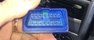
oh, and even though my car is from 2004, it is 1.5l and 8kl with EURO-2, and is equipped with an ODB-1 connector. I googled it: it turns out that ODB-2 was already installed but on 16kL cars with EURO-3 from earlier years. I also had to buy an adapter with
Adapter OBD-II 16pin to GM12
I ordered everything from the online store, along with the cords I received a disk with programs for diagnostics and a bunch of different information on diagnostics. I configured all the com ports on the laptop and went into the garage with the laptop to try. I plugged it in, turned on the ignition, bam, and the fuel pump immediately began to hum without stopping. Naturally, nothing happened and I abandoned the matter (and this was last year at the end of autumn). Well, it’s already warm - there is a desire to resume this business. When I rang the adapter, I didn’t really understand anything, one rings 3 at a time, some don’t ring at all, I decided to redo it all. As you know, for diagnostics via the K-line you only need 3 wires (channels): 1) potassium itself 2) +12V 3) -12V aka ground, ground
OBD2 pinout - 16 PIN
Brands and years:
Gasoline passenger cars and light commercial vehicles manufactured or imported into the United States since 1996 (US CARB and EPA legislation) and in Europe (EOBD) since 2000-2001 (European Union Directive 98/69EG) and Asia (mainly since 1998). ).
Conclusions and their purpose:
| № | Color | Purpose |
| 2 | J1850 Bus + | |
| 4 | Body grounding | |
| 5 | Signal Ground | |
| 6 | Line CAN-High, J-2284 | |
| 7 | K-line diagnostics (ISO 9141-2 and ISO/DIS 14230-4) | |
| 10 | J1850 Bus- | |
| 14 | Line CAN-Low, J-2284 | |
| 15 | L-line diagnostics (ISO 9141-2 and ISO/DIS 14230-4) | |
| 16 | Power supply +12V from battery |
Diagnostic connector pins for used protocols
Pins 4, 5, 7, 15, 16 - ISO 9141-2.
Pins 2, 4, 5, 10, 16 - J1850 PWM.
Pins 2, 4, 5, 16 (without 10) - J1850 VPW.
The ISO 9141-2 protocol is identified by the presence of pin 7 and the absence of pins 2 and/or 10 on the diagnostic connector.
If pin 7 is missing, the system uses the SAE J1850 VPW (Variable Pulse Width Modulation) or SAE J1850 PWM (Pulse Width Modulation) protocol.
All three data exchange protocols operate via a standard OBD-II J1962 connector cable.
OBD1 pinout - 12 PIN (GM12)
Description:
OBD1 (GM12) connector is rectangular in shape, consists of 12 contacts.
Brands and years:
All injection models, except for some models after 2002, which have an OBD-II connector.
Access and location:
Pinout:
| M | L | K | J | H | G |
| A | B | C | D | E | F |
| Key * | |||||
* Connector Keying - A design element of a removable connector that ensures the correct orientation of the plug and socket.
Errors on-board computer VAZ 2114
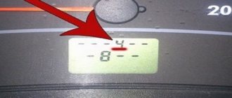
To check the computer, you need to reset the mileage for the day on the dashboard and turn on the ignition at the same time. Then, by pressing the button on the windshield wiper lever, you will see on the display the computer firmware version with error codes, if any.
Main error codes:
- 2 - The machine's mains voltage is too high.
- 3-fuel level sensor.
- 4-fluid cooling temperature sensor.
- 5-malfunction of the overboard temperature sensor.
- 6-motor overheating.
- 7 - critically low oil pressure.
- 8-disadvantages in the braking system.
- 9-battery is low.
The most common on-board system errors are:
- Code 4 mainly appears when the engine is not warmed up enough, or when the sensor indicating the amount of fuel is turned on.
- Code 6 indicates an overheated engine.
- Code 8, when there is a shortage of brake fluid in the system.
Having identified existing errors, you can reset them; just press and hold the car’s daily mileage button for a while.
Before making a transaction to purchase a car, be sure to check the on-board system. Make sure there are no system errors. Or you will discover interesting facts about the condition of the car. For example: engine heating, oil pressure, etc.
Basic error codes for VAZ 2114 injector: decoding
Note!
The table is also relevant for version 2115.
Exhaust system – 0000
- 30 – open circuit of the oxygen sensor heater to the catalytic converter;
- 31 – also with a short circuit to the car body;
- 32 – similar with a short circuit to 12V;
- 36-38 – the same value as 30 only for the output sensor.
Air line defects – 0100
- 102/103 – Mass air flow sensor open circuit or signal violation;
- 112/113 – sensor lines t ˚ overboard, impulse violation;
- 116 – engine overheating;
- 117/118 – damage to the DTOZH circuit;
- 122/123 – TPS line, short circuit or insulation failure;
- 130 – failure of the oxygen sensor in front of the catalyst;
- 131/132 – similar element, signal level violation;
- 133 – slow response of DK1 to commands;
- 134 – break in the power cable DK1;
- 136 – DK2 is broken;
- 137/138 – short circuit or violation of wiring DK2;
- 140 – fuse DK2 burned out;
- 141 – the heater of the same device is broken or damaged;
- 171/172 – excessively lean or enriched fuel mixture.
Features of checking wires included in various devices
The specificity of this situation is that the wiring in the case under consideration consists of one linear conductor with a supply voltage of 12 Volts. In this case, the metal body of the car is used as the second (common or “ground”) conductor, where, as a rule, there is nothing to break.
To prepare the on-board network for inspection, you first need to disconnect the positive terminal from the battery, after which you can safely begin work. Testing of on-board wiring is organized according to the previously described linear circuit testing scheme.
When checking the “ground” of a car, the main attention is paid to the quality of contact of the supply terminals with the body
Electric heating element
Based on the indicator readings on the multimeter, it is possible to make a continuity test on an element such as a water heating element. During the test, the control probes of the device touch the two contact plates of the heater and evaluate its internal resistance using the indicator.
In addition to the heating element itself, when checking boilers and similar devices, it is very important to ring the supply cable for unwanted contact with the device body. For this purpose, one of the multimeter probes is connected in turn to the input contacts; while the second end is constantly held on the heater body
If the digital multimeter shows some resistance during measurement, this means that the protective sheath of the supply cable is damaged. To prevent electric shock to the user, it should be replaced with a new one.
Using a multimeter, you can test the power circuit of any lighting device by testing the wiring and auxiliary elements (switches, in particular) for a short circuit or open circuit. To do this, first of all, you should ring two linear chains ending directly at the contacts of the light bulb.
When testing linear chains, be sure to check the serviceability of the switch located in one of them, as well as the reliability of connecting the conductors to its contacts.
We also note that using this method it will be possible to ring the windings of a linear transformer or electric motor and verify their integrity or the presence of a break (short circuit).
WHAT TO DO WHEN A BC STOPS WORKING
This sometimes happens when the on-board computer does not work. What do experts advise to do in this case? The first step is to determine the type of malfunction of the device. If it does not show “signs of life” at all, you need to check fuse F3, which is installed in the power supply circuit of the VAZ 2114 processor. If replacing it does not “revive” its operation, check the connection connectors.
There is no point in describing the essence of the process of repairing such a complex electronic product, since for this, in addition to having the necessary devices and tools, you also need to have an education in the field of electronics.
How to withdraw BC
Let's not prevaricate, but rightly note that the quality and functionality of the standard on-board computer offered for the VAZ 2114 leaves much to be desired.
Therefore, the decision to install an alternative with expanded functionality and capabilities on the part of car owners is quite fair.
Before removing the BC, make sure that the device is no longer covered by warranty. If you interfere with the design of the machine yourself, you may lose money. However, the new “fourteenth” VAZ models are a rarity, which is why few cars are still under factory warranty.
Having decided all these nuances and selected a new on-board computer, you can safely begin dismantling the old BC.
Disconnect the negative terminal from the battery installed in the engine compartment of your car. This is necessary in order to protect yourself from electric shocks, as well as to avoid damage to all wiring. Remove the radio that is on your console. Remove the outer panel from the audio system. Now you can fully remove the entire cassette cassette
All wires connected to it must be detached. A hole will open in front of you, where you stick your hand and carefully open the computer unit mount. Take out your outdated or unusable on-board vehicle, having first disconnected all the wires connected to it. If you are not going to install a new BC, then the dismantled wiring must be connected. Otherwise, you will have problems while operating the car. A number of devices are connected to your on-board computer
Therefore, they will also have to be disabled. Do this carefully and gradually. No sudden movements. Otherwise you will have to change the wiring. If a new bookmaker claims to take the place of the old one, start connecting at this stage. Insert the radio into place, assemble all the components in their places, observing the reverse dismantling sequence.
The work is not difficult, but it will take some time to complete it.
Features of using the USB K-Line adapter:
- operates in a wide range of device supply voltages from 8.0 to 18 V;
- recommended temperature for use of the device is from -40 to 40 ° C;
- providing communication with a direct one-wire interface directly to a standard connector;
- connecting diagnostic testers;
- simple communication with the vehicle's ECU;
- protection against short circuit to ground;
- low current consumption during operation.
Although the K-Line diagnostic protocol is still widely used today, it no longer plays a significant role in new developments of automotive systems for solving diagnostic tasks performed via K-Line. However, car manufacturers around the world have not ruled out the fact that many vehicle ECUs still use K-Line technology, ensuring the use of this technology for some time to come. ECUs with K-Line interface are still used in passenger cars.
Why do you need an on-board computer?
In previous articles we have already talked about what an on-board computer is. what is it for and what types are they? But let me repeat myself so that you clearly understand all the advantages of having an on-board computer, and there are probably no disadvantages, except perhaps spending money on the purchase and that’s all.
Let's take, for example, the on-board computer STATE 115×24. With this model in your possession, you can:
- set the radiator fan start temperature; this function is very useful, for example, in winter, when you can control the temperature of the coolant, thereby monitoring the temperature of the heater radiator.
- The function of drying and warming up the spark plugs before starting the engine is very useful.
- The function of resetting settings and ECU adjustments is needed to switch to gasoline with a higher or lower octane number (from 92 to 95 and vice versa), and this function is also needed to reset settings after a long trip with increased load on the engine.
- The ability to read errors allows you to monitor the condition of the car and change non-working sensors and elements in a timely manner.
Errors when connecting/operating the on-board computer
Error: “No connection with the controller” or “break in the K-line.”
This error indicates that the K-line is not connected or a contact break has occurred. Check the wire according to the diagram described above. Most likely the contact has come off the diagnostic block.
Error: Incorrect readings of the sea temperature sensor.
If your temperature outside is -40, then this indicates that the wire to the temperature sensor has broken, or there is no such sensor at all. If the temperature is, for example, -25, but it’s only -10 outside, then you need to replace the sensor with a working one.
Possible causes of malfunction of the on-board computer and the main ways to eliminate them
One of the most common reasons is a lack of communication with the controller or line-K. What does the current error indicate and what needs to be done:
- the appearance of this error directly indicates a broken contact, or a poor connection of line-K with the additional block;
- The first thing you need to do is check line K according to the diagram;
- in most cases, the cause of this malfunction is a contact break between line-K and the diagnostic block.
How to diagnose a car
- Connect contact “B”, which has the diagnostic block and “ground”;
- Turn the ignition key to the third position, do not start the car;
- First, the “CHECK ENGINE” lamp displays code 12 with 3 flashes. It shows that the diagnostic programs are working. On the VAZ 2110 this happens in this order: the lamp blinks briefly 1 time (which should be considered the designation of number 1). After a pause lasting at least 2 seconds, it flashes 2 times in a row (two). So we got the number two. And this is repeated 3 times so that the driver understands these signs;
- After the diagnostic program has declared its serviceability, it will begin to display error codes, if there are any, of course. In the same way - flashes and pauses.
Where is the correct connector?
Most often it is located under the torpedo. By the way, it can be located on both the right and left sides. On certain models, the device is located near the steering column. Can be located to the left and below it. For cars that have a Europanel, the connector is located under the cigarette lighter.
Attention! The required connector can be covered with a decorative panel.
It is worth mentioning that two additional contacts, which are located on the diagnostic block of the VAZ 2114, are needed for the external air temperature sensor. After you make the connection, you will need to activate the K-line. It is necessary in order to transfer all important information to the device.
This is done as follows:
- The meter wire is connected to the second contact of the connector block.
- The second end is led to the diagnostic connector.
- The connection is made using the M-socket at the EURO 2 block, or to the seventh socket of the EURO 3 block.
- Connect the on-board computer and install it in the planned location.
Video “Why the ECM does not communicate during testing”
From the video below, you can find out why there may be no communication between the ECM and the laptop during diagnostics (the author of the video is the Billye espada channel).
Please tell me. The on-board computer says “no connection with the maintenance controller.” What to do in this situation?
- Will BOSCH 0-280-150-996 injectors fit the January 7.2 ECU? – 2 answers
- Why does the on-board computer constantly reboot when starting the engine? – 2 answers
- Interruptions in the operation of the VAZ 2114 engine - 2 answers
- Should I flash the VAZ Samara controller? – 2 answers
- How to replace the Bosch ECU for January 2115? – 1 answer
Does the on-board computer have any connection with the controller?
If the engine starts and runs without problems, then you need to deal with the B/C, there is often a break in the K-line (the wire to the OBD-2 comes off), one might say - one of the main wires.
Terminal No. 7 of the diagnostic connector.
Probably the wire of the hog computer jumped out of it.
Even more useful tips in a convenient format
Interruptions in the operation of the VAZ 2114 engine
Why does the on-board computer constantly reboot when starting the engine?
break to the line VAZ 2110
Hello everyone. Auto VAZ 21102, late 2003. I've owned the car for exactly a year, the problems appeared about 2-3 months ago. The point of creating a topic is that I don’t want to immediately go to the service station, because maybe someone has encountered a problem and it can be solved simply.
First things first: 1. Three or four months ago, the check light started to light up from time to time, BC (State) gave the error K-line break. I worked closely on the car, changed a lot of things after the purchase, but I never got around to electrics, I confess.
2. Three months ago the error K-line break appeared very strangely - sometimes 10 times a day, sometimes I drove for a week without receipts. 3.
Two months ago, another error began to appear from time to time, I don’t remember the number, but according to the decoding - Broken line DD (Knock Sensor) 4. Around the same time, terrible confusion began to happen with the battery (it was very old) - I bought a new battery (not very expensive , but in any frost it turned well, did not bring it home). Here's the problem. I park the car in the evening, sound the alarm, everything is ok. When I come in the morning, the car beeps, indicating that the alarm has gone off. Pantera alarm.
The battery drains very badly, to the point that it is impossible to start the car in the morning, the relay clicks, but the starter does not turn. Sometimes it happens that the alarm does not go off, but the battery still goes to zero. So it goes.
The last few days I have been disconnecting the battery at night so that I am not late for work in the morning. I understand that I need to go to the station and carry out diagnostics. But work, time, money.
Naturally, if the problem is not solved by my efforts with the information support of Saratov residents, I will still go to the service station, then I will write down what the problem was. But it would be very cool if I found the reason and solved the problem myself. I bought a knock sensor (Boshevsky, for 600+ rubles), I’ll change it tomorrow, the error will most likely disappear. But I have no idea what to do with the rest. Taken from. https://www.autosaratov.ru.
Things are like this. Yesterday I stopped at a gas station, stood in line, and turned off the engine. When it was time to start - FUCK! I turn the key to the first position,
When converting foreign-made cars to an ECM with an ECU January 5.1, there is a need to install a knock sensor from the same
Hello everyone, a friend of mine has this problem, can anyone tell me what it is? Auto VAZ 2112 2002, 1.5 16V mileage at the time of purchase 91000, at the moment
Things are like this. Yesterday I stopped at a gas station, stood in line, and turned off the engine. When it was time to start - FUCK! I turn the key to the first position,
Hello, I bought a VAZ 21124 3 months ago, drove it for a month and decided to change the filter and oil. Consumables in general. The first thing I did was change the air
Checking the connector contacts
We have already carried out a preliminary check and made sure that power is supplied to the ignition module. Now it’s worth dealing with the contacts separately. With the ignition on, you need to connect a test lamp to contact A and contact B.
The control can be a regular low-power 12-volt lamp with soldered wires, or you can use a car test probe with a 12-volt voltage indicator.
Checking the ignition module
To check the functionality of the module, we attach the contacts from the test lamp or probe to terminals A and B, then crank the engine with the starter.
In this case, everything is in order with contacts A and B.
How to check the ignition module of a VAZ-2114
Interruptions and jerking when driving, a shaking engine, difficult starting or even engine failure are the main signs of failure of the ignition module.
The difficulty of diagnosing on your own is that the module combines several devices at once , and it itself is made in a single housing, and there is no way to check each device separately. At least with your bare hands. Nevertheless, something can be done in order to, if not repair, then at least know for sure the cause of the malfunction.
Checking the quality of contacts
First of all, without dismantling anything, it is worth checking the quality of contact on all blocks of the low voltage circuit , as well as establishing the presence of contact on the high voltage wires.
Checking the presence of power on the ignition module
Checking the voltage on the ignition module pads
In order to know that it is the module that is faulty, let’s check whether power is supplied to it. To do this, we find the connector in the block, and there we look for a contact marked with the letter A. To control the power supply to the module, take a multimeter, set it to measure alternating current up to 20 V , install one probe (negative) to engine ground and turn on the ignition. We install the second probe on terminal A on the block. If the electrical equipment is in good working order, the multimeter will show 12 V, which means that power is supplied to the module, we look further for the cause of the malfunction.
Instructions on how to check the K-line
Most often, the solution to the problem really lies in breaking the K-line wire. That is, the wire has simply moved slightly out of the block (the APS block of the immobilizer, or the BC block) and there is no longer any contact.
If you have checked all the contacts, but the on-board computer still does not see the K-line wire, then you can proceed as follows:
1) Check the voltage on the K-line. We set the multimeter to the mode for measuring constant voltage, connect the red probe to the K-line, and the black probe to ground to any point on the body. The readings on the device should be 12+-2V. You cannot use a lamp to check the voltage, because it has a load.
2) If on your VAZ the connector with the APS is disconnected, then check for the presence of a jumper in the APS block between pins 9 and 18.
3) The problem may be in the immobilizer (the K-line signal comes, but disappears after the immobilizer). Check for the presence of a K-line on pin 18 of the APS block. Using the same method, you can check whether there is a break between the APS block and the BC block.
4) Interference or broken wire. Try replacing the wire from the BC to the diagnostic connector with a new, shorter one.
Does your car have an on-board computer?
K Line connection problems
K - Line adapter ( VAG COM ) does not connect
When making a K-Line adapter yourself or purchasing it in a store, users in some cases encounter problems connecting the adapter.
This problem has two subtypes:
— Problem when connecting the adapter to a PC (with our K-Line 409 adapter, the kit includes a video instruction on how to use the device, we recommend that you read it if you have any questions)
— Problem connecting the K Line 409 (VAG COM) adapter to the car
To solve the first problem, you need to install the driver for the device located on the disk, then go to the device manager and see if your adapter is displayed correctly. If in the device manager you see your adapter in the COM ports and LPT section without any question marks, etc. then you can rest assured that the drivers are installed correctly. To be more confident, you can double-click on it to find an inscription stating that the device is working normally.
If your adapter is indicated with a question mark or is located in the other devices section, apparently you have not installed the driver and you need to reinstall it.
We select our device, select, update the driver and specify the folder with the drivers, then click next and see the installation process, otherwise select another folder and repeat the operation until we achieve success.
If you installed the driver correctly, but when connecting to the car the connection does not occur, first check the cable for functionality, to do this, install the Vasyadiagnostic program, then in the settings section select the port number on which your adapter is located and click the test button ( The car engine must be running or the ignition is on).
If you receive a message about successful detection of the adapter, the next step is to select a program for your car from the disk that comes with the adapter and diagnose it.
If you receive a message that the adapter was not found or the port is closed, then double-check the port number in Device Manager and that the device driver is installed correctly. If everything is done correctly, check the functionality of the cable on another car and another PC.
If, when connected via another PC on another car, the adapter works but refuses to work on your PC, then there may be a problem with the installed OS, antivirus, or computer components. Most often, if the cable on your PC works on another car, but refuses to work on your car, the problem is a broken K-line wire. Perhaps the wire has simply moved a little out of the block (the APS immobilizer block) and there is no normal contact. If you have checked the contacts on the car and everything is in order, but the cable still does not work, then you need to perform the following steps:
Example of wire continuity
Continuity of wires in buzzer mode
Situation: the socket in one room does not work. The user's task will be to find the cause of the failure. To solve it you will need:
- See if the automation in the shield worked. If the elements are turned on, de-energize the specific line or apartment completely.
- Remove the socket from the socket box and perform a visual inspection for external defects and quality of contacts.
- On modern models, the terminal blocks ring.
- If the socket is not damaged, test the quality of the connection of the conductors in the junction box next to the socket.
- The main cable in the distribution box must be broken, connected to the conductors under the socket and routed to the next consumer.
- There are 3 twists in the distribution box - neutral, ground and phase. Use the tip of the probe to touch the exposed twist.
- The second tip rings the socket contacts in turn. You can fix one probe on the contact, and check the twist with the second.
There are no terminal blocks for standard sockets.
Wire testing process
The measurements have several nuances:
- If the twist is without defects, it makes sense to test the live wiring. It is necessary to supply current by turning on the switchboards.
- If you are in doubt about the color marking, the phase is determined by touching the indicator screwdriver - the diode should light up.
- Working and protective grounding are checked in ACV mode greater than 220 V. The red probe is in phase, the black one is used to find zero and ground. The working grounding N is reflected in the range of 220 A, the protective grounding PE is less than 220 V.
- It is taken into account that electricians do not always route wires into the junction box. The outlet can be powered from the adjacent one or the elements of the adjacent room can be placed at common points on the walls.
- Due to the length of the probes 30-50 m, it is allowed to connect the socket contacts with a jumper and a continuity tester in the junction box.
