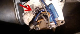
VAZ 2110 window lift diagram
Electric windows (ESP) are convenient devices for controlling the side windows of a car, which are controlled by a special button and make it possible to lower or raise the side windows without rotating the previously used handles. This option is provided only in some modifications of the VAZ car, but nothing prevents you from purchasing a ready-made unit and installing it yourself.
The most preferred are rack-type ESPs, so as an example we will describe the process of their installation.
The connection diagram for the window regulator on a VAZ-2110 car is as follows:
- remove the negative terminal from the car battery to stop the supply of voltage to the on-board power supply network;
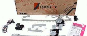
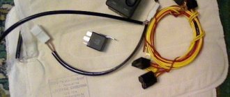
- we take the wires that come standard with rack-and-pinion window lifts and make a kind of harness out of them that makes connection easy;
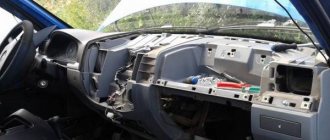
- remove the car mounting block, which will require unscrewing the self-tapping screw that secures the special latch;
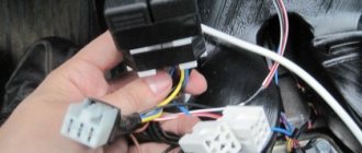
- turn the block over and carefully install block Ш1 of the pre-prepared wiring harness into the corresponding connector;
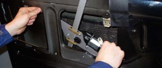
- dismantle the door trim;
- we pull the wires to the electric window drive. To do this, you will need to carefully pass them through the holes in the door itself and the body pillar on the desired side.
After this, buttons or keys are installed that will be used to control the power windows. Depending on your desire, they can be attached either to the door trim of a VAZ-2110 car, or to an existing control panel. In the first case, you will need to use an additional wire, which will allow you to equip the key backlight.
Connecting power windows VAZ-2109
Owners of a VAZ 2109 car can replace power windows with electric windows. On 2109 cars, electric windows can be connected via standard wiring, which already has everything provided for connecting an ESP.
This circuit is used to connect ESP on more “rich” configurations of the nine and it is advisable to use it when connecting independently. Below are diagrams for connecting an ESP with fuse blocks of new and old models.
Wiring diagram for power windows on a VAZ 2109 with an old-style mounting block (17.3722):
- 1 - Mounting block
- 2 - Ignition relay
- 3 — Ignition switch
- 4 — Right door electric window motor
- 5 — Left door electric window motor
- 6 - Right door power window switch
- 7 - Left door power window switch
- K7 - Power window power relay
- A - To terminal “30” of the generator
- B - To the wiring harness block connected to the heater lever illumination display
- B - to the heater lever illumination display
- G - conventional numbering of plugs in the gear motor block
Electrical problems
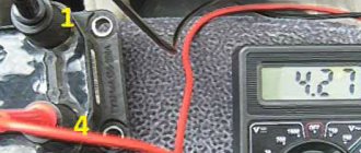
First of all, check the power window fuse (on the VAZ 2110 it is fuse F5). If it is intact, then we check the voltage at the terminals of the window motor using a multimeter or a regular 12V light bulb. If there is no voltage, then we carefully check the wiring, the power window relay, and then the control unit (if any). See also Mounting block.
| Why doesn't the window regulator work? There are many reasons for the malfunction, ranging from the banal freezing of windows to failure of the window lifter mechanisms. Do you know how to check the window regulator? |
Installation of electric windows on a VAZ
The procedure is performed in the following sequence:
- temporarily remove the glass seal located on the inside of the door;
- remove the glass, and then dismantle the window regulator fastening mechanism;
- we install devices that will operate from an electric drive;
- connect the negative terminal to the battery and check the operation of the new window regulator;
- We install the glass in place and trim the door.
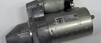
Unlike conventional mechanical devices, power windows are not equipped with traditional gear reducers, but with a special drum. The shaft of a DC electric motor is inserted into its hole located in the center. In this case, the motor is only a component of the gearmotor, on which, as we found out earlier, the speed and quality of raising and lowering the windows depends.
Installation of the lifting device is quite simple. It starts with disconnecting the battery. After this, use a curved screwdriver to unscrew 3 screws, unfasten the door trim latches and remove the door pocket. Using a thin screwdriver, pry off the handle (latch) of the window lifter - the tip of the tool is inserted into the recess between the latch and the socket.
The handle itself is removed. At the next stage, the car door opening handle is dismantled. To do this, use a screwdriver to pry the handle cover and remove it. Now use a screwdriver to remove the 2 fastening screws that were hidden by the cover plate. After this, the handle can be removed without much difficulty. Using a screwdriver, you can also remove the power window button, which serves to lock the door.
After removing 6 pistons, the trim covering the car mirror adjustment mechanism is also removed. As a result, it remains easy to dismantle the door trim. Armed with a 10mm wrench, unscrew the 2 bolts that hold the auto glass clips. Next, 2 nuts securing the lifting mechanism, nuts of the upper and lower fastenings, and 3 nuts securing the lifting mechanism are unscrewed in sequence.
Upon completion of the described stage, it is time to remove the lower guide pin of the lifting device from the door panel. To facilitate and simplify such an operation, the upper pin of the guide must be bent using a screwdriver. Now the entire lifting mechanism can be safely removed through the resulting opening in the door frame.
>Electric window diagram VAZ 2110-2111-2112
Power window lifter.
Electrical circuit diagrams for the VAZ 2110 car. Diagnostics of the electrical equipment for the Lada 2110 car. Instructions for troubleshooting the lighting system. Repair of generator and starter for Lada 2111 - 2112.
Electric windows are used to raise and lower the door windows and are installed on a part. These VAZ 2110 have a plug in the door trim instead of a window lifter handle, and there are corresponding backlit switches on the floor tunnel lining.
In the window lift mechanism, instead of a gear reducer, only a drum is installed, into the hole of which the output shaft of the VAZ 2111 gear motor is inserted.
The gearmotor consists of a worm gearbox and a DC electric motor with excitation from permanent magnets. The direction of rotation of the shaft depends on the direction of the current in the armature winding. To protect against overloads, a built-in thermobimetallic fuse is used. The faulty gear motor is replaced.
Voltage is supplied to the switches only when the ignition is on through a relay of type 904.3747-10 located at the rear of the VAZ 2112 mounting block.
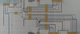
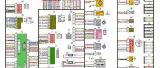
- Wiring diagram for power windows
- 1 – mounting block
- 2 – ignition switch
- 3 – right front door power window switch
- 4 – right rear door power window switch
- 5 – electric window motor reducer of the right front door
- 6 – electric window motor reducer of the right rear door
- 7 – electric window motor reducer of the left rear door
- 8 – electric window motor reducer of the left front door
- 9 – left rear door power window switch
- 10 – left front door power window switch
- 11 – relay for turning on electric windows
- A – to power supplies
- B – to the instrument lighting switch
- C – conventional numbering of plugs in power window blocks
Serial connection - diagram
We connect the output of additional button 1 in the driver's door to input 6, and output 7 to input 3 of the main button on the passenger door. We cut the wires in the block connecting contacts 5-6 and 6-3. The minus of contact 5 now goes only to the backlight, and contacts 6 and 3 now take output from additional buttons 1 and 7 of the driver's door. Installation in parallel will result in short-circuiting during lifting and lowering. Power wires are highlighted in bold.
Read more: How often to change 5w40 engine oil
When using trigger buttons, connect all ESP motors only through a relay. When using a conventional door closer, relays are also needed, since they are not in the long-press closer block and all the current flows through the buttons and wires from them.
Installation and connection of electric windows on a VAZ 2110
Electric windows have greatly simplified life for car owners and increased the level of comfort while using the car. The devices are controlled by a single button, which allows you to adjust the opening of the side windows, taking into account the current situation, and without the need to rotate the handles. The downside is that such a mechanism is not installed on all VAZ 2110 cars, but only in some modifications. But this drawback can be corrected by installing window lifters yourself. We will look at how to do this correctly in the article.
How to choose a window regulator for a VAZ 2110
If you are planning to install and connect window regulators yourself, start by choosing the appropriate device model. The key criterion when choosing is reliability. The installed product must perform its functions for a long time and work without failures. Finding suitable options in the modern market is not difficult:
- Slat mechanisms are window lifters that are not easy to use.
- Traditional designs. The advantages of these products include ease of installation and affordable price. Disadvantages - small service resource (when compared with other types of competitors).
- Rack and pinion windows. Such mechanisms are in greatest demand. They are considered the most suitable and are the most reliable.
Major breakdowns of power windows
Depending on the configuration of the car, it can be equipped with both mechanical (manual) and electric windows. It is from which of these options is installed on your car that you should begin searching for the corresponding faults.
Thus, for manually operated window regulators the following types of damage are most typical:
- failure of rods (bending of rods when excessive force is applied);
- jamming of traction joints;
- spontaneous unwinding and loss of fasteners.
It is quite simple to fix all these malfunctions with your own hands; you just need to correctly dismantle the window regulator and carry out repairs (we will tell you how to remove the device mechanism below).
In turn, if the power windows on a VAZ 2114 do not work, then the possible reasons for this may be:
- fuse blown (at the same time playing the role of a fog light fuse);
- failure of relay K5;
- break in the power supply circuit of the lifts;
- drive motor burnout.
In this case, you should start your search by checking the fuses designated F5 and F16 (this can be done by replacing them with new ones or by regular “diagnosis”). If the fuses are working, then you should continue to look for the problem; if not, replace them with others designed for the same amperage.
The next thing to check is relay K5 in the power window circuit. To test it, you need to replace it with a known working (new) relay and check the functionality of the device. If a malfunction is detected, the old relay must be replaced.
The next stage of the test will be to “test” the wires in the power window circuit using a multimeter. If a break is detected, it will be necessary to replace the burnt wire with a new one with the same (or slightly larger) cross-section.
If the wiring is in order, then all that remains is to check the functionality of the electric drive itself. The easiest way to do this is to connect the lift motor to the network “directly”. A failed electric window motor cannot be repaired and must be replaced with a similar one.
Lada 2110 Carburetor › Logbook › Installing power windows on a VAZ 2110
I would like to save money when installing window regulators. I'll tell you how. So: The window regulator for 2110 costs 1,500 rubles for the front assembly and 1,600 rubles for the rear. Total - 3000 front + 3200 rear = 6200 rubles + installation.
We buy the following: 2 powerful motors for 750 rubles per front. You can do it cheaper, but the front ones are driven more often and would need more power. = 1500 RUR 2 engines "Kalina" x 450 RUR = 900 RUR 2 trapezoids x 250 RUR front bare (without motors) = 500 RUR 2 trapezoids x 250 RUR rear bare (without motors) = 500 RUR 8 bolts of the "receiver" - that's what through threaded rods with a 6-sided boss of 2 washers and elastic inside x 15 RUR = 120 RUR 1 block of buttons 4 pcs. = 120 rub. 16 meters of installation wire for 4 squares of copper stranded soft x 15r = 156r It turns out 3796 rubles. 35% cheaper. We also need door trim pistons. After much torment, I installed the Prirovsky ones. They hold up better than standard hedgehogs. Before installation, we assemble the station - insert the square of the motor drive into the fitting boss. CAREFULLY! The lug with the cable tries to jump away! If the cable unwinds, it will take a long time to insert it back with mats. It’s better to open the engine, coat the gasket with sealant (if there is one) and just coat the space under the gasket (if there is none) and thoroughly hammer the grease onto the worm. It is better to lubricate not lithol or grease, but CV joints. The one that doesn't freeze in the cold. Spray the brush assembly well with silicone grease. Not thick! And not VD-40. We attach the motor to the fittings with the same receiver bolts.
Installation is simple: 1. Remove the door trim. 2. Lower the glass 3. Unscrew the window regulator. 4. We thread it outwards. 5. Install the motor. When installing, you can slightly tighten the glass fastening. Because the glass gets a little warped in the frame and gets stuck. And if you make them a little looser, the glasses themselves find the right position and become as they should without jamming. 6. All holes match, no need to drill anything. 7. We stretch the wires through the door. 8. We check the installation by connecting to the battery (I check by connecting a screwdriver to the battery) 9. I stretch the wires under the central tunnel to the gear shift knob. HERE I have a button block installed. 10. I pull the buttons from the nearest powerful wire fuse (4 mm). 11. Checking the polarity. 12. I close everything in place.
Note. Why did I use 4 square thick wires? And not just sniffles? The fact is that motors consume a lot of current. And there is a lot of heating of the thin snivells. In addition, due to heating, the voltage drops significantly. On thin wires - up to 2 volts. As a result, it closes slowly and eats a lot. On thick wires it buzzes SOOO quickly. Faster than many foreign cars.
Window lifter.RF › Blog › Replacing the rear windows of the VAZ-2110
This report on the installation of electric windows in the rear doors of a VAZ-2110 was prepared by our buyer Andrey Aleksandrovich Serebrennikov from Sevastopol, as part of his participation in our promotion.
And finally the long-awaited rear electric windows have arrived.
It all starts with removing the door card. We unscrew everything that can be unscrewed, and then pull off the card with the pistons, you just need to pull it off carefully, you can break off the leg under the pistons.
Then unscrew the 3 “8” nuts that hold the lowering lever, and the 2 “10” nuts that secure the guide to the door, be careful not to lose the growers!
Then unscrew the 2 bolts securing the guide to the metal base of the window.
Holding the base of the window with your hand, we take out the entire mechanism and place it at the bottom of the door, now we need to secure the window.
Since there was no stick at hand to support the bottom, an L-shaped wrench was used in this way:
Now the window does not try to move down, and will not interfere with us pulling the entire mechanism out.
We pull out the mechanism through the lower left hole of the door (for the left rear door), the whole difficulty lies in removing the mechanism block itself, since the pulley is very long and does not want to fit through.
Then I checked the power windows for functionality by connecting it to the wire going into the door and pressing the button so that I wouldn’t have to take it all back out later.
We begin to put the ESP inside the door. Compared to the stock one, I didn’t experience any difficulties; everything fits in quite quickly.
We begin to attach it all to the door. And then I discovered a small problem: there are only 2 fastenings of the ESP unit to the door and they are designed for nuts at “10”, while the standard ones were at “8”. It's good that I take it with me in reserve. In total, instead of 5 fastenings we get 4, but now everything is turnkey to “10”.
We check the functionality and fasten the card in place. And we are waiting for the deluxe 2 cards to arrive so that we can fully enjoy the view of the salon!
Selecting window regulators for installation on a VAZ-2110
If you want to install electric windows on your car, you will first need to choose the most reliable device that will serve for many years without causing any problems. On the modern market you can find the following options:
- traditional cable structures, which are relatively easy to install, but differ from others by not having a very long service life, wear out quickly;
- strip devices that are not very convenient to use;
- rack and pinion window lifters, which are deservedly recognized as the most suitable and reliable in operation.
When choosing devices suitable for your car, pay attention to factors such as:
- the speed of raising and lowering the glass, which largely depends on the gear motor installed on the car;
- the ability to use the device in the cold season;
- noise level during product operation.
Taking into account all these factors, you will be able to choose window lifters that will not only work flawlessly, but also will not create any problems in specific operating conditions.
How to install and connect power windows on a VAZ-2110
The most preferred devices are rack type, so we will describe the installation process as an example. The connection diagram for the window regulator on a VAZ-2110 car is as follows:
- remove the negative terminal from the car battery to stop the supply of voltage to the on-board power supply network;
- we take the wires that come standard with rack-and-pinion window lifts and make a kind of harness out of them that makes connection easy;
- remove the car mounting block, which will require unscrewing the self-tapping screw that secures the special latch;
- turn the block over and carefully install block Ш1 of the pre-prepared wiring harness into the corresponding connector;
- dismantle the door trim;
- we pull the wires to the electric window drive. To do this, you will need to carefully pass them through the holes in the door itself and the body pillar on the desired side.
After this, buttons or keys are installed that will be used to control the power windows. Depending on your desire, they can be attached either to the door trim of a VAZ-2110 car, or to an existing control panel. In the first case, you will need to use an additional wire, which will allow you to equip the key backlight.
Types of window regulators and the main causes of their breakdowns
Today the following types of window lifters are in use on VAZ:
- rack type (experts consider them the most reliable of all known designs);
- cable;
- plank.
Depending on which company produced the product in question, it can be installed in the car door as standard, or, if it does not fit in size or other technical characteristics, it can be altered without unnecessary problems.
Since both domestic and imported gear motors can be installed on the lift, the described devices, depending on the type and origin of the electric motor, may differ:
- by the speed at which the glass is raised or lowered;
- according to the noise level recorded during operation of the window lifter;
- if possible, its normal operation in winter conditions.
The parts in question can fail for a number of reasons, which can be summarized into two main groups: mechanical and electrical failures. The list of possible reasons looks like this.
- The whole design doesn't work. The cable has broken or become jammed. Lifting mechanism malfunction.
- The electric motor failed due to moisture getting into it. Such a malfunction occurs quite often, since the gearmotor has a leaky housing into which water leaks, which is why rust forms inside the device over time. As a result, spreading corrosion destroys the entire mechanism.
- The power window relay has failed. The performance of this component can be determined by replacing the problematic relay for testing with a guaranteed working one.
- The corresponding fuse has blown. If after installing a new element the device starts to work, then this is the reason. If the new fuse blows again, you need to look for the short circuit.
- Short circuit in the circuit. Its location is determined by which fuse burns when turned on. The cause of this malfunction can be either burnt out wire insulation or a failed gear motor or mechanism switch.
- Breakage of the switch. Determined after replacing the problematic one with a new, known-good switch.
- Break in the common circuit. This can happen due to a mechanical break in the electrical wire, disconnection of the block or poor contact in it.
Installation process of electric windows
In addition, it is necessary to install the power windows themselves. The procedure is performed in the following sequence:
- temporarily remove the glass seal located on the inside of the door;
- remove the glass, and then dismantle the window regulator fastening mechanism;
- we install devices that will operate from an electric drive;
- connect the negative terminal to the battery and check the operation of the new window regulator;
- We install the glass in place and trim the door.
Our instructions in pictures will help you understand the installation procedure in more detail.
Features of connecting power windows
Unlike conventional mechanical devices, power windows are not equipped with traditional gear reducers, but with a special drum. The shaft of a DC electric motor is inserted into its hole located in the center. In this case, the motor is only a component of the gearmotor, on which, as we found out earlier, the speed and quality of raising and lowering the windows depends.
Before installing a new power window, you must select the correct device based on its technical characteristics, and also make sure that the product is in a fully folded state. Otherwise, you are unlikely to be able to install the product efficiently and ensure its flawless operation after connecting it to the vehicle’s on-board network.
You've probably noticed that on almost all foreign cars the power window buttons are duplicated on each car door. To connect additional ESP buttons in the doors, you need to run an additional three wires into each door .
Standard ESP connection diagram
Changed to this scheme (here without rear ESP)
Connection diagram for additional ESP button.
How the additional ESP button is made on Kalina
To install one duplicate button in the door you will need:
- 2x contact (plastic connector) block male + female 1 pair
- Large male terminals 2 pcs.
- Mom large 2 pcs.
- Mom little 7pcs
- Earth 1pc.
- Power window button 1 pc.
- Button installation cup 1 pc.
- Power window button connector 1 pc.
- Wire diameter 0.75 4 met.
- Door pistons 7pcs
If your ESP buttons have been moved to the doors. then the insert into the harness for additional buttons will look like this. The meaning is that we need to run 3 wires :
- Ground (Ground, in theory, can be taken into the doors, but there is not always good contact there, so it is better to run a separate ground wire)
- +12V “after ignition” (with power window relay at ChYa)
- illumination (take it from the cigarette lighter, since it is in the middle between the doors.)
Disconnect the negative terminal from the battery.
We look for +12V on the ESP relay (black and white wire) to it and screw both of our red +12V
Then we climb through the door. There are 2 wires going to the ESP motor - gray and blue, through a connector. Unplug the connector:
We take 2 wires (I have black and black and white), of such length that we can reach from the original chip with the blue and gray wire going into the corrugated door to our future button. We crimp 2 large male terminals onto them and insert them into the connector. We put it on the chip with blue and gray going into the corrugated door, so that the black comes from the gray, and the black and white comes from the blue:
Insert the wires into the button connector:
- Red +12V
- Black mass
- White backlight
- Black with gray wire chips
- Black and white with blue wire chips
We crimp with small “mothers” and insert the ESP buttons into the connector. We do it according to the scheme:
- Red +12V to slot 2
- Black ground - in slot 5
- White backlight - in slot 4
- The black wire from the gray wire of the chip goes into slot 6
- Black and white from the blue wire chips - into slot 3 (THREE).
Do not mix up the button connector sockets! That's not all, we need two more short wires, through which we will now connect our button to the ESP motor, like we'll do it as before. For beauty, we take the same colors of wires that were attached to the original chip going into the corrugated door, i.e. black and black and white. It will be like a continuation of the original wires, and in the middle of them is our button. We insert the black wire into socket 1 of the button connector. Black and white - into socket 7. We crimp the other ends of these wires with large “mothers” and put the purchased connector on them so that when putting this connector on the dangling chip going to the ESP motor:
- The black wire went to the gray ESP motor chips
- Black and white - to the blue wire of the ESP motor chip.
In principle, that's all. Don't pay attention to the orange wire in the photo - it's a mass for heating the mirrors.
You can use the button from Kalina. it is more beautiful and a little more expensive than the VAZ 2110.
Electrical circuits of cars VAZ 2110, VAZ 2111, VAZ 2112, repair
Electrical diagrams of VAZ 2110, VAZ 2111, VAZ 2112
Features of the new model
The electrical wiring of the VAZ 2114 has a different design than its predecessor:
- Inside the car;
- In the engine compartment;
- In the rear of the body.
The new engines were equipped with a more powerful ignition system, as a result of which the wiring diagram of the VAZ 2114 to the injector had some peculiarities.
- A wiring harness was added to connect to the terminal of the ignition module, which supplied impulses to the spark plugs;
- A wiring harness has been added for connecting to the electronic switch;
- Wiring has been added to connect the adsorber valve to the injection system controller.
Photo of the ignition module pinout
For reference: there is a misconception that the ignition module replaces the coil. In fact, the ignition module has 2 coils and 2 switches at once. The first coil supplies an impulse to the 1st and 4th cylinders, and the second - to the 2nd and 3rd cylinders.
The wiring for the VAZ 2114 has undergone changes not only due to the addition of new electronic devices, but also due to the automaker's further plans to modernize the functionality of the car.
- It is possible to connect heated exterior mirrors;
- It is possible to install heated front seats;
- It is possible to install front fog lights, etc.
Connection diagram for fog lights: instructions for VAZ 2114
Engine compartment
The first thing that owners of a carburetor power system pay attention to is the modified wiring diagram of the VAZ 2114 to the injector. To operate on a lean mixture, the vehicle is equipped with:. To operate on a lean mixture, the vehicle is equipped with:
To operate on a lean mixture, the vehicle is equipped with:
- Forced fuel injection system directly into each cylinder;
- Installation of an increased power ignition system on the vehicle;
- Self-learning ECM - electronic engine control system.
The ignition module on the VAZ 2114 allows you to increase spark generation power
For reference: a feature of EURO 3 standards is the low content of unburned fuel components in the exhaust gases. To this end, the car's fuel system reduces the amount of gasoline in the air-fuel mixture, compensating for this by better filling the cylinders due to forced fuel injection.
To ignite a lean air-fuel mixture in the engine cylinders, it is necessary to provide a more powerful spark at the moment when the piston is at TDC (top dead center).
This is realized by installing an ignition module, the operating principle of which is implemented:
- The generator produces alternating electric current;
- It is supplied to the ECU, which converts it to direct current;
- From the control unit, current is supplied to the windings of the ignition module coils;
- High voltage is generated in the secondary winding (according to the law of induction) of the coils;
- It is supplied to the spark plugs at the start of the ignition phase.
Advice: if you want to understand the operation of a car’s ignition and power system, it would be a good idea to watch video materials from a school physics course. Or find videos on automotive websites.
Vehicle interior
For the VAZ 2114 model, the automaker developed and installed a new dashboard, which differed from its predecessor:
- the absence of a glove compartment in the upper part - it was moved lower;
- new instrument panel;
- the advent of an on-board computer
For reference: the on-board (trip) computer gave readings about the outside air temperature, the voltage in the vehicle's on-board network, current fuel consumption, power reserve and other parameters.
Torpedo VAZ 2114 with a new instrument panel, better known as “Europanel”
The emergence of new electronic components has led to a change in the wiring diagram of the VAZ 2114 panel.
- a wiring harness with a connector for the on-board computer was added;
- an outside air temperature sensor has appeared, installed in front of the radiator;
- The voltmeter relay appeared.
Wiring diagram for power windows on a VAZ 2114
In addition, a wiring harness was added to the front door panels, which were equipped with electric windows.
The diagram below shows:
- mounting block with terminal “A” to the power source and “B” to the external lighting switch;
- relay for turning on electric windows “K5”;
- switch for the right front door “2” and “5” for the left door;
- gearmotor of the right door “”3” and “4” - left door;
- ignition switch "6".
The wiring for the VAZ 2114 window regulators was also completed with an actuator unit
Diagram of electric windows VAZ 2110, VAZ 2111, VAZ 2112, Lada Ten
Electric windows are used to raise and lower door windows and are installed on some cars. These VAZ 2110 cars have a plug in the door trim instead of a window lifter handle, and there are corresponding illuminated switches on the floor tunnel lining.
In the window lift mechanism, instead of a gear reducer, only a drum is installed, into the hole of which the output shaft of the VAZ 2111 gear motor is inserted.
The gearmotor consists of a worm gearbox and a DC electric motor with excitation from permanent magnets. The direction of rotation of the shaft depends on the direction of the current in the armature winding. To protect against overloads, a built-in thermobimetallic fuse is used. The faulty gear motor is replaced.
Voltage is supplied to the switches only when the ignition is on through a relay of type 904.3747-10 located at the rear of the VAZ 2112 mounting block.
Possible malfunctions and ways to eliminate them
Now we suggest that you familiarize yourself with the causes of the main malfunctions that can occur in the operation of a joint venture. If there is a problem, the window regulators will either refuse to work at all, or will function incorrectly or be noisy.
Main causes of problems:
- Malfunctions in the operation of the electrical circuit, that is, wiring. If the wiring is damaged, the control motor of the joint venture will no longer receive a signal about the need to raise and lower, and accordingly, the operation of the joint venture will be impossible. The wiring may be damaged, in some cases the reason lies in insulation failure or oxidation of contacts. Damaged sections of the electrical circuit must be replaced, oxidized contacts must be cleaned or replaced.
- Inoperability of the gear motor. Electric motor failure usually occurs after several years of intensive use. If the unit fails, normal operation of the joint venture will be impossible, the drive must be repaired or replaced, here the specific nature of the breakdown must be taken into account.
- Damage to the control module with keys. If all the power windows do not work at once, then most likely the reason lies in the inoperability of the control unit. Perhaps the contact with the car's electrical network has been broken or the board itself has failed. The board itself must be replaced. If only one or more lifts do not function, then the reason may lie in poor contact of the control button with the network. Again, you need to get rid of the oxidation and reconnect the button.
- Mechanical wear of the gear. This problem is usually caused by long-term and intensive use of the joint venture; the gear teeth can be damaged as a result of wear. Repair is impractical; the gear must be replaced.
- The fuse responsible for the operation of the joint venture has blown. The fuse element may be located in the mounting block with all other fuses and relays. But if you installed the joint venture yourself, then the fuse may be located next to the battery. A failed device must be replaced (the author of the video is the V Village Life channel).