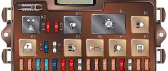
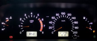
The main symbols that are found on the dashboard of absolutely any car of the VAZ family are: speedometer, fuel gauge, tachometer and sensors to indicate engine temperature.
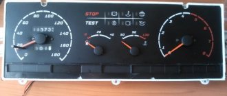
Pinout of the dashboard of VAZ2105, 2106, 2107
Old panel (with oil pressure gauge)
In addition to the presence of an oil pressure indicator, it is worth noting that this instrument panel does not have an air damper indicator lamp (choke), and the emergency oil pressure lamp is located next to the pressure indicator. Because of this, it contains lamps for low brake fluid levels and fog lamps.
White 6-terminal block X1:
- Gasoline level sensor
- Turn signal indicator lamp
- Battery charge sensor (voltmeter -)
- Gasoline level warning lamp
- Overall plus (+)
- Battery charge sensor (voltmeter +)
White 8 terminal block X2:
- Fog lamp warning lamp
- High beam warning lamp
- Dimensions indicator lamp
- Empty
- Battery charge indicator lamp
- Brake fluid level warning lamp
- Empty
- Parking brake warning lamp
Orange 6-terminal block X3:
- General minus (-)
- Tachometer VAZ
- Instrument lighting
- Oil pressure sensor
- Oil pressure warning lamp
- Coolant temperature sensor
New instrument panel (with econometer)
Here, everything is the other way around - there is no oil pressure indicator (instead there is an econometer), instead of a brake fluid level lamp there is a suction lamp (or an engine management system lamp on injectors), and instead of a fog lamp lamp there is an oil pressure lamp.
White 6-terminal block X1:
- Gasoline level sensor
- Turn signal indicator lamp
- Battery charge sensor (voltmeter -)
- Gasoline level warning lamp
- Overall plus (+)
- Battery charge sensor (voltmeter +)
White 8 terminal block X2:
- Dimensions indicator lamp
- High beam warning lamp
- Oil pressure warning lamp
- Empty, but there is a terminal in the wiring that goes to the brake fluid level sensor
- Battery charge indicator lamp
- Indicator lamp for the air damper (choke) or engine control unit for injectors
- Empty
- Parking brake warning lamp (handbrake)
Orange 6-terminal block X3:
- General minus (-)
- Tachometer (if this contact is empty, then the tachometer is on pin #4)
- Instrument lighting
- Empty, and if not empty - to the tachometer
- Empty
- Coolant temperature sensor
Second connection diagram option
Pinout of the dashboard VAZ2108, 2109, 21099
Connection diagram of the instrument cluster before 1996.
1 – relay-interrupter for the parking brake warning lamp; 2 – tachometer with voltage stabilizer; 3 – instrument cluster lighting lamp; 4 – temperature indicator; 5 – BSK control unit; 6 – fuel level indicator; 7 – resistor 50 Ohm, 5 W; 8 – control lamp “CHECK ENGINE” for the toxicity reduction system; 9 – control lamp for high beam headlights; 10 – side light indicator lamp; 11 – backup warning lamp; 12 – warning lamp for unfastened seat belts; 13 – control lamp for left direction indicators; 14 – resistor 470 Ohm, 0.25 W; 15 – electronic voltmeter; 16 – control lamp for right direction indicators; 17 – warning lamp for emergency oil pressure; 18 – fuel reserve warning lamp; 19 – control lamp for the carburetor air damper; 20 – indicator lamp “CHECK ENGINE” for the fuel injection system; 21 – parking brake warning lamp.
Instrument cluster wiring diagram after 1996
1 – tachometer; 2 – instrument cluster lighting lamp; 3 – temperature indicator; 4 – BSK control unit; 5 – fuel level indicator; 6 – control lamp “CHECK ENGINE” for the toxicity reduction system; 7 – control lamp for high beam headlights; 8 – side light indicator lamp; 9 – backup warning lamp; 10 – warning lamp for unfastened seat belts; 11 – control lamp for left direction indicators; 12 – battery charge indicator lamp; 13 – control lamp for right direction indicators; 14 – warning lamp for emergency oil pressure; 15 – fuel reserve warning lamp; 16 – control lamp for the carburetor air damper; 17 – indicator lamp “CHECK ENGINE” for the fuel injection system; 18 – parking brake warning lamp; B1 – resistor 91 kOhm; B2 – resistor 50 Ohm, 5 W.
Pinout of the dashboard of VAZ2110, 2111, 2112
- fuel reserve warning lamp;
- dashboard lighting lamps;
- right repeater indicator lamp;
- left repeater indicator lamp;
- VAZ plug block;
- coolant temperature sensor;
- indicator lamp for external lighting;
- carburetor air damper warning lamp;
- oil pressure warning lamp;
- handbrake indicator lamp;
- battery charge indicator lamp;
- VAZ tachometer;
- indicator light “CHECK ENGINE”;
- speedometer dashboard;
- brake fluid level warning lamp;
- hazard warning lamp;
- high beam indicator lamp;
- fuel level indicator.
| White block (X1) | Red block (X2) | ||
| 1 | Housing (weight) | 1 | To terminal “W” of the fuel level indicator sensor |
| 2 | Tachometer (low voltage input from ECU) | 2 | Fuse F19 + 12V power supply |
| 3 | Tachometer (high voltage input from coil) | 3 | Housing (weight) |
| 4 | Const +12V from battery (via 6th fuse) | 4 | Instrument lighting switch |
| 5 | Coolant temperature sensor. | 5 | Turn signal RIGHT |
| 6 | Fuse F1 (side light) | 6 | Turn signal LEFT |
| 7 | Throttle valve (“choke”) | 7 | Brake fluid level |
| 8 | Check Engine Light | 8 | To the trip computer |
| 9 | Fuse F19 + 12V power supply | 9 | Speed sensor |
| 10 | Fuse F19 + 12V power supply | 10 | Terminal “T” fuel gauge |
| 11 | Parking brake, terminal “VK” | 11 | Fuse F3 (high beam) |
| 12 | Generator output “D” | 12 | Hazard switch |
| 13 | Oil pressure sensor | 13 | To terminal “50” of the ignition switch |
Pinout of the dashboard of VAZ2113, 2114, 2115
There are 26 contacts on the VAZ-2114 instrument panel, each of which is responsible for the operation of the indicators of this panel. If a plus is supplied to the panel, then each contact displays information about the state in which the car is currently located.
White block (X1)
Red block (X2)
- Housing (weight) - black
- To ambient temperature sensor - cyan-magenta
- Tachometer (low voltage input from ECU) - brown/purple
- Fuse F16 (to terminal 15 of the ignition switch) - orange
- Tachometer (high voltage input from coil) - yellow
- Housing (weight) - black
- To fuse F3 of the mounting block (+battery) - white-purple
- Instrument lighting control - white
- Coolant temperature sensor. - green-white
- Turn signal RIGHT - blue
- To fuse F10 of the mounting block - brown
- Turn signal LEFT - blue-black
- Brake fluid level - pink-blue
- Check Engine Light to ECU Controller - White-Purple
- To the trip computer - brown
- To the ECU controller - pink and black
- Speed sensor - gray and yellow
- To the fuel gauge sensor - orange
- To the fuel gauge sensor - pink
- To the parking brake switch - brown-blue
- Fuse F14 of the mounting block - green-black
- Alternator terminal "D" through fuse panel - brown and white
- Hazard switch
- Oil pressure sensor - blue
- To terminal “50” of the ignition switch - purple
In addition, special indicators and signal sensors are installed on the instrument panel, and the panel itself is controlled by a special electronic unit. Having disassembled the instrument panel, you can see that there are two pads inside it: red and white. And all inputs, outputs and fuses are connected to the plug. If the sensors fail, they will need to be replaced. It is also better to replace damaged or oxidized wires. Indicator lights, like any other, sometimes burn out. Undoubtedly, they need to be replaced with whole ones. Along with them, the lamp sensor often burns out.
VAZ 2114 instrument panel connection diagram
- rear window heating switch;
- rear fog lamp switch;
- switch for headlights and direction indicators;
- mounting block;
- wiper switch;
- fog light switch;
- on-board control system display unit;
- instrument panel harness block to additional harness;
- instrument cluster;
- instrument panel harness connector to the on-board computer harness;
- instrument panel harness connector to the ignition system harness;
- instrument panel harness connector to the side door harness;
- fuse 16 A;
- fuse 16 A;
- ignition switch;
- lighting switch;
- heater electric motor;
- additional resistance of the heater electric motor;
- ignition switch unloading relay;
- rear fog light relay;
- starter relay;
- socket for connecting a portable lamp;
- cigarette lighter;
- instrument panel harness connector to the glove compartment lamp wiring harness;
- illuminator;
- illuminator;
- illuminator;
- heater switch;
- instrument lighting regulator with rheostat;
- brake light switch;
- horn switch;
- hazard switch;
- heater control lamp;
- fuse 16 A;
- seat heating relay;
Useful: Pinout of twisted pair network 8 wires - color scheme
Another variant of the connector pinout diagram
- checking the brake fluid level indicator. If you apply +, the brake light will light up. You can connect it to the red wire of the ignition switch, then, just like on 2110/2114, the lamp will be checked when the starter is turned on.
- Hazard warning lamp will light up when + is applied.
- high beam lamp, connect to the green-black wire.
- fuel level indicator, connect to the pink-red wire.
- to the speed sensor.
- speed signal output to the on-board computer. If there is one, then take the speed signal from this contact.
- Brake fluid level indicator, connect to the pink-blue wire near the lamp above the cigarette lighter. In the VAZ-2107, the lamp works the other way around: the sensor connects the lamp to ground and it lights up. You will have to either leave the lamp where it is, or in the new device, solder the lamp to + and swap the diodes (in this case, to check the lamp, pin 1 must be connected to ground, for example, to the parking brake lamp), or remove the black wire from the sensor on the tank, and connect instead the orange one from the EPHH unit, or the blue one from the ignition coil, while the diode in the wiring (between the beard and the glove compartment) must be disconnected; if this is not done, there will be a short circuit.
- left turn lamp, connect to the blue-black wire of the steering column switch block.
- Right turn lamp, connect to the blue wire of the steering column switch pad.
- instrument lighting, connect to the white wire.
- ground, connect to the black wire.
- power supply of devices, connect to the orange wire.
- if the device is simple (without microcircuits, etc.), then connect it to the blue-red wire (fuel reserve lamp), if there is a display under the tachometer, then connect it to the temperature sensor (take from a VAZ-2114, one contact to the device, the other to ground, place it either in the passenger compartment or in the engine compartment, but far from the engine and so that the wind does not blow).
- ground, connect to the white-black wire.
- low-voltage tachometer input (from the ECM), connect to the brown-blue wire.
- high-voltage tachometer input (from the coil), connect to the brown-blue wire.
- If there is a display under the speedometer, then connect it to the red and white wire at the brake light switch.
- coolant temperature gauge, connect to the green-white wire.
- outdoor lighting lamp, connect to the yellow wire.
- carburetor choke cover lamp, connect to the gray-orange wire.
- go to the ECM lamp. If the machine is injection, then connect one of the contacts to the orange wire, and the other to the remaining one.
- go to the ECM lamp. If the machine is injection, then connect one of the contacts to the orange wire, and the other to the remaining one.
- power supply of devices, connect to the orange-blue wire.
- handbrake lamp, connect to the brown wire.
- battery charge lamp, connect to the brown-white wire.
- low oil pressure lamp, connect to the gray-blue wire.
Description and location of indicators and instruments on the panel
The VAZ instrument panel may differ depending on the vehicle model.
In general, domestic car equipment can be divided into three groups:
- shields for classic cars - VAZ 2101-VAZ 2107;
- devices for the Lada Samara family of cars - 2108, 2109, 21099;
- PP VAZ of the tenth family - 2110, 2111, 2112, etc.;
- tidy of more modern VAZ models - Priora, Granta, Kalina.
Seven dashboard
Since the last two options have already been discussed in previous articles, we will not focus on them.
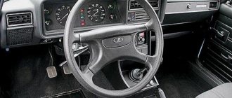
The VAZ 2107 dashboard includes the following components (all indicators are marked in accordance with the numbers indicated in the diagram below):
- Voltmeter. This device shows the current voltage in the car's electrical network.
- Speedometer showing the speed of the vehicle.
- Odometer. Essentially, this is a counter that shows the mileage traveled by the car.
- Tachometer. This device demonstrates the engine speed. It is not advisable to allow the needle to move into the red zone.
- Antifreeze temperature sensor. Likewise, the needle must not be allowed to move into the red zone, as this will lead to overheating of the power unit.
- One of the features of the instrument panel on a VAZ is the presence of an econometer. Thanks to this device, the driver can choose the most optimal travel option in terms of fuel consumption.
- Indicators. From top to bottom - turn signals and light alarm, Check icon (for engine diagnostics, placed on injectors), discharged battery, side lights, high beams, low oil pressure, parking brake.
- Another car mileage counter, only in this case we are talking about daily mileage.
- Indicator light that turns on when there is a minimum amount of fuel left in the gas tank.
- Fuel level sensor.
Nine panel with a low panel.
Separately, we should dwell on the dashboards of the cars of the Samara family. The panel on VAZ 2108, 2109 and 21099 can be low or high - in this case it all depends on the torpedo installed in the cabin.
Low panel devices include the following elements:
- Speedometer.
- DTOZH - engine temperature.
- Voltmeter.
- Fuel level sensor in the tank.
- Minimum gasoline volume indicator.
- The econometer and its purpose were discussed above.
- Car daily mileage counter.
- Odometer, where the total mileage is displayed.
- STOP screen.
- The low battery indicator, as well as its appearance on the instrument panel with a low trim, may be caused by incorrect operation of the generator unit.
- Indicator of the opening of the air damper or suction.
- Light signaling.
- Brake fluid reduction icon.
- Handbrake activation indicator.
- An icon for reducing engine fluid pressure in the system; its appearance is usually associated with a decrease in oil level.
- Turn signals.
- Dimensional lighting.
- Rear fog lights activation symbol.
- High beam activation indicator.
- Symbol for turning on the rear window heating system.
Photo gallery “Tidying Samara with a high panel”
1. Nine shield with high panel
2. Description of the shield elements
3. Description of the indicators on the dashboard
Instrument panels VAZ VDO (LED)
You can install a more beautiful and convenient panel with LED indicators, the so-called VDO panel. Here VDO is the panel manufacturer.
| Connecting VDO on a Kalina car | ||
| 1 | Pink-white | To electric power steering |
| 2 | Blue and white | To the hazard warning indicator |
| 3 | Gray-blue | To emergency oil pressure sensor |
| 4 | Brown blue | To the parking brake switch |
| 5 | Yellow-blue | To the immobilizer control unit |
| 6 | Black | To the airbag control unit |
| 7 | Yellow | To the outside light switch |
| 8 | Blue | To the right turn signal switch |
| 9 | Blue with black | To left turn signal switch |
| 10 | White-blue | TO ECU |
| 11 | . | To brake pad wear sensor |
| 12 | . | To seat belt sensor |
| 13 | Black | To the traction control control unit |
| 14 | Red-blue | “RESET” key on the steering column switch |
| 15 | Pink-blue | To brake fluid level sensor |
| 16 | Black | To ABS |
| 17 | Green | To the high beam switch |
| 18 | White | To the instrument cluster light control |
| 19 | Brown | Panel weight |
| 20 | White-red | Terminal “30” |
| 21 | Orange | Terminal “15” |
| 22 | Yellow-red | To fuel flow sensor |
| 23 | Orange-white | MK key “forward” |
| 24 | White black | MK key “back” |
| 25 | Black and white | Outside temperature sensor (-) |
| 26 | Yellow-green | Outside temperature sensor (+) |
| 27 | Pink | Fuel level sensor |
| 28 | Grey | Speed sensor |
| 29 | Green-white | Coolant temperature sensor |
| 30 | Brown-red | Tachometer (low voltage) |
| 31 | . | Official. Panel diagnostics. |
| 32 | Brown-white | Terminal “L” of the generator relay regulator |
High instrument panel
According to the diagram presented below, the VAZ 2109 with a high panel has the following components.
| Item number | What is this |
| 1. | Ignition switch |
| 2. | Hazard switch |
| 3. | Windshield wiper and washer control lever |
| 4. | Radio socket |
| 5. | Central nozzles of the interior heating and ventilation system |
| 6. | On-board computer (not available on all trim levels) |
| 7. | Dashboard |
| 8. | Glove compartment lid (glove compartment) |
| 9. | Side nozzles of the interior heating and ventilation system |
| 10. | Speaker (loudspeaker) trim |
| 11. | Shelf |
| 12. | Power window switches (available on certain trim levels) |
| 13. | Cigarette lighter |
| 14. | Control panel for heating and interior ventilation system |
| 15. | Gearbox shift lever |
| 16. | Hand brake lever |
| 17. | Ashtray |
| 18. | Carburetor choke handle |
| 19. | Gas pedal |
| 20. | Brake pedal |
| 21. | Clutch |
| 22. | Horn switch (horn) |
| 23. | Instrument panel light switch |
| 24. | Headlight hydrocorrector |
| 25. | Front seat heating switch (available as standard) |
| 26. | Rear fog light switch |
| 27. | Front fog lamp switch (not available on all trim levels) |
| 28. | Rear defogger switch |
| 29. | Hood lock drive lever |
| 30. | Turn signal and light control lever |
| 31. | Outdoor optics switch |
| 32. | Instrument cluster |
In order to eliminate certain malfunctions, monitor the operating parameters of the engine and vehicle systems, it is necessary to learn how the instrument cluster with a high panel is designed when you first get acquainted with the VAZ 2109.
VAZ instrument panel indicators - explanation
- coolant temperature gauge.
- tachometer;
- left turn signal indicator lamp;
- right turn signal indicator lamp;
- speedometer;
- fuel level indicator;
- fuel reserve warning lamp;
- side light indicator lamp;
- service brake system warning lamp;
- high beam indicator lamp;
- reset button;
- mileage indicator;
- warning lamp for turning on the hazard warning lights;
- "check engine" warning light;
- time and temperature indicator;
- battery charge indicator lamp or battery lamp;
- parking brake warning lamp;
- oil pressure warning lamp;
- reserve.
VAZ dashboard indicators play an important role in informing the user about malfunctions. They help prevent errors in the system, so it is important to know which indicator means what. How does the panel work? If any problem occurs, the sensor immediately sends information to the panel, and the driver will see an orange signal light up.
The earlier version of the instrument panel had some other symbols, such as emergency oil pressure, handbrake engaged, Chek Engine light, and several others that indicate minor operating errors, but which are no longer used.
Bottom part
Let's look at the indicators at the bottom of the control panel. If they don’t light up, it means the machine is working normally, and when any of them lights up, this indicates a malfunction in certain components. Most often, this is a signal that repairs are needed, and the sooner the better. From left to right:
- The indicator on the far left at the bottom is the air damper light (if you have a carburetor engine);
- Icon in the form of an oil can. If this light comes on, it means there is insufficient oil pressure in the engine. An alarming signal. You need to stop, find the reason;
- A round icon with the letter P inside on the control panel indicates that you have the parking brake on, which, as you know, should be turned off when moving away;
- Indicator of a fault related to the generator or battery (a symbolic image of the battery is shown on the indicator). Perhaps the battery is not charging from the generator, there is an open circuit, or the generator belt is loose or broken. In any case, your intervention and repairs are needed, otherwise troubles cannot be avoided;
- If the engine is running and the Check Engine indicator is on on the control panel, this is the most unpleasant thing for the driver, since it indicates serious malfunctions in the engine. In general, when this indicator lights up, it is recommended to stop driving and turn off the engine. Most likely it needs repairs;
- Typically there is a red triangle above the Check Engine. It lights up when the “hazard light” is on - an emergency signal sign;
- The headlight light indicates that the high beam is on. Designed to control headlights: when an oncoming car appears, do not forget to switch to low beam;
- A very important indication icon on the front panel (in a red circle) is a signal that there is not enough brake fluid. Perhaps it is leaking somewhere, which it is advisable to find out as soon as possible and, if necessary, carry out urgent repairs and replenish the level;
- The icon of a burning light is a control for turning on the dimensions;
- In addition to the indicated lights, the front control panel has time indicators (and a button for setting hours and minutes) as well as a display that shows the total and daily mileage. On the new panel, this display may be narrow.
Decoding of car error codes is presented in this material:
Repair or replacement of the VAZ dashboard
If on a car on the instrument panel none of the indicators installed on it work (speedometer, odometer, tachometer, fuel level and coolant temperature indicators), then the first thing the driver will have to do is check the integrity of fuse F3, which is located in the mounting block . If it has burned out, then before replacing it, you need to find the reason why it burned out, otherwise the newly installed new fuse will have the same fate as the previous one. Most often, fuses burn as a result of a short circuit.
Even if the fuse is intact, then do not be lazy to take it out and check the condition of the contacts. There are cases when the contacts oxidize, and the electrical circuit in this place is interrupted. After making sure that the fuse is intact, the next step is to check the ignition relay, which is located inside the car to the left of the steering column. It is attached to a pin upside down. In the block where this relay is inserted, you can try to short-circuit the power wires using a jumper. If the instrument panel comes to life, the ignition relay will have to be replaced.
If the ignition relay is working properly, there are only two possible reasons for the instrument panel not working: the ignition switch and the mounting block. Before installation on the VAZ-2109 car, the ignition relay and lock contacts often burned out and had to be cleaned by disconnecting the contact group from the lock itself. After changes were made to the principle of supplying voltage to the ignition switch, its contacts began to burn very rarely, but the likelihood of this phenomenon still remained. On the mounting block, in its board, tracks may burn out; in order to see this, the mounting block will have to be removed from the car.
In addition to the reasons listed above, which can lead to failure of the instrument panel, it is also necessary to check the reliability of the fastening of the ground wire. Most common problems:
- burnout of incandescent lamps or failure of the LED group;
- oxidation of connectors;
- electrical wiring fault;
- failure of the fuse box;
- damage to the common contact board;
- no weight on the body (minus) or damage to the dimensions system.
To find a fault, you must use diagnostic equipment, a tester or a voltmeter. If a breakdown is found, you can begin repairs.
Installation and repair instructions
If you are faced with the problem of a failure of the dashboard of a VAZ 2109 vehicle, then the best option would be to replace the dashboard yourself. To properly replace, you will need instructions for dismantling and installing the shield, which are given below. To perform these steps, you only need screwdrivers - flat-head and Phillips-head. The instructions are given on the example of a low panel, but in general they are identical for other versions of instrument panels. Don't forget to disconnect the battery!
Unscrew the screws of the shield visor. Disconnect the speedometer cable. Disconnect the ecometer hose.
- First of all, you need to de-energize the system; to do this, disconnect the terminals from the battery.
- Using a Phillips screwdriver, unscrew the plastic trim around the steering wheel. You don’t have to remove it, but it is advisable to do so for greater convenience.
- You can also disconnect the steering column switches by simply unplugging the wiring harness.
- Using a Phillips screwdriver, unscrew the two small screws securing the dashboard visor and remove this element.
- After these steps, you can compress the springs and remove the electronic panel from the center console.
- The next step is to disconnect the speedometer cable. It is necessary to be very careful when dismantling so as not to damage the cable, especially if it is old. Otherwise, it will need to be replaced.
- Next, turn off the white outlet and remove the econometer hose.
- Then you should disconnect the cable for resetting the car’s daily mileage data from the speedometer.
- The final step will be to disconnect the red connector and dismantle the shield itself. A new panel is replaced and installed, after which further assembly is carried out in the reverse order.
As you can see, the procedure for replacing the instrument panel is not particularly complicated - just do everything in accordance with the instructions and there will be no problems in the further operation of the device.
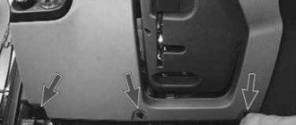
Removing the car dashboard
- Using a Phillips screwdriver, remove the three screws that secure the center console;
- remove the cover, the protrusion located at the bottom, remove the protrusion from the bracket;
- Using a nozzle, unscrew the five screws located in the console on the right and remove the screen;
- Disconnect the terminal with the (-) sign from the battery. If there is a radio receiver, you need to remove it, remove the plug from the shield;
- Disconnect the wires coming from the cigarette lighter, remove the cartridge;
- Using a narrow screwdriver, remove the handle from the levers;
- pull the handle towards the heating and fan switch;
- unscrew the two screws above the panel and the two located under it using a screwdriver;
- unscrew the screw located behind the panel;
- Also unscrew the two self-tapping screws securing the cover;
- disconnect the harness and wire connectors. To avoid confusion when installing the panels, you should mark the order in which they are connected;
- unscrew the fastening bolts;
- unscrew the two self-tapping screws, those that secure the bottom bracket using an 8 key;
- unscrew the self-tapping screw securing the light guide and remove it;
- Also unscrew the screws securing the heating unit;
- remove lamp sockets;
- after removing the external parts, remove the decorative insert;
- unscrew all nuts with a 21 key;
- hydrocorrector, remove its lamp;
- Unscrew the screws that are attached to the cross member on the left.
- Finally, the panel itself is removed. The panel is assembled accordingly in the reverse order.
In general, the repair work is quite doable even with your own hands, but before starting dismantling work, you need at least a pinout mapped on paper, otherwise it will be difficult: you will need to “trace” every wire and every connection that is on the “path” from devices to the power button.