Dismantling and assembling suspension components of the VAZ 2115 Lada
The front struts on VAZ 2114-2115 cars wear out much faster than the rear ones, and this is due to the fact that the front part of the car bears a large load, since the main units are located there. If the shock absorbers are leaking, or are starting to leak heavily in potholes, then it would be best to completely replace them. Many people are used to dealing with such problems at a service station, although if you try a little, you can do it all on your own. The main thing is to have all the necessary tools and equipment at hand. Below is a detailed list of everything:
- spring ties
- ball joint or steering wheel remover
- pliers
- hammer
- keys for 13 and 19 as well as similar heads
- crank and ratchet handle
- breakdown
I recommend that you first familiarize yourself with the video, which will be presented below, and then read my photo report on the work done.
Front suspension of VAZ 2115 Lada
- Repair manuals
- Repair manual for VAZ 2115 (Samara 2) 1997+.
- Front suspension
4.1.1 Front suspension Features of the device Possible malfunctions, their causes and methods of elimination Determining the technical condition of the suspension parts on the car Checking and adjusting the wheel alignment angles Removing and installing the front suspension Checking the telescopic strut and shock absorber of the rear ...
4.1.2 Features of the device The front suspension is independent, telescopic, with hydraulic shock absorbers, coil springs, lower wishbones with braces and a stabilizer bar. Rice. 4.1. Front suspension assembly: 1 – upper telescopic support…
4.1.3 Possible malfunctions, their causes and methods of elimination Cause of malfunction Method of elimination Noise and knocking in the suspension when the vehicle is moving 1. Suspension struts are faulty 1. Replace or repair the struts 2. The bolts for fastening the brace brackets or the bolts for fastening the stabilizer bar to the ...
4.1.4 Determining the technical condition of suspension parts on a vehicle During each maintenance, as well as during repairs, it is necessary to check the condition of the protective covers of the suspension ball joints, paying special attention to the absence of mechanical damage to the covers. Find out if there are any cracks or traces of contact with road obstacles on the suspension parts...
4.1.5 Checking and adjusting wheel alignment angles Checking and adjusting wheel alignment angles is carried out on special stands according to the instructions for the stand. WARNING Checking the wheel alignment angles is mandatory when replacing or repairing suspension parts that may result in a change in the alignment angles...
4.1.6 Removing and installing the front suspension Removal Place the car on a lift or inspection ditch and brake it with the parking brake, remove the wheel cap, loosen the front wheel mounting bolts and unscrew the hub mounting nut. Raise the front of the car and remove the front wheel. Rice. 4.3. Vypres...
4.1.7 Checking the telescopic strut and shock absorber of the rear suspension on a stand To determine the functionality of the telescopic strut and shock absorber, check their operating diagrams on a dynamometer stand. Take operating diagrams according to the instructions supplied with the stand, after performing at least 5 working cycles, at a working fluid temperature of (20±5) °C, often...
4.1.8 Disassembly and assembly of suspension units Disassembly and assembly of the telescopic stand Disassembly Fig. 4.1. Front suspension assembly: 1 – upper support of the telescopic strut; 2 – upper support cup; 3 – compression stroke buffer with protective casing; 4 – compression buffer support; 5 – suspension spring; 6 – lower spring support cup;…
↓ Comments ↓
1. General information
1.0 General data 1.1 Technical characteristics of vehicles 1.2. Vehicle controls 1.3. Vehicle operation 1.4 Vehicle maintenance
2. Engine
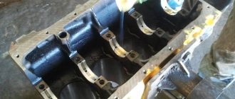
2.1 Possible malfunctions, their causes and methods of elimination 2.2 Removal and installation of the power unit 2.3 Disassembly and assembly of the power unit 2.4 Disassembling the engine 2.5 Assembling the engine 2.6 Running in the engine after repair 2.7 Checking the engine on the car after repair 2.8. Cylinder block 2.9. Connecting rod and piston group 2.10. Crankshaft and flywheel 2.11. Cylinder head 2.12. Camshaft and its drive 2.13. Lubrication system 2.14. Cooling system 2.15. Supply system
3. Transmission
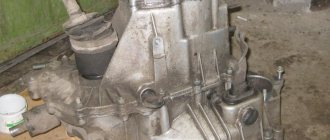
3.0 Transmission 3.1. Clutch 3.2. Gearbox 3.3. Front wheel drive
4. Chassis
4.0 Chassis 4.1. Front suspension 4.2. Rear suspension
5. Steering
5.0 Steering 5.1. Features of the device 5.2 Possible malfunctions, their causes and methods of elimination 5.3 Inspection and testing of the steering control of the car 5.4. Removal and installation 5.5 Checking the gap between the rack stop and the nut 5.6. Disassembly, technical condition check and assembly 5.7 Replacing the rivets of the elastic coupling of the steering shaft
6. Brake system
6.0 Brake system 6.1. Features of the device 6.2 Possible malfunctions, their causes and methods of elimination 6.3. Checking and adjusting brakes 6.4. Vacuum booster 6.5. Main cylinder 6.6. Pressure regulator 6.7. Front wheel brake 6.8. Rear wheel brake 6.9. Dismantling and assembling wheel cylinders 6.10. Parking brake system
7. Electrical equipment
7.0 Electrical equipment 7.1. Wires and fuses 7.2. Battery 7.3. Generator 7.4. Starter 7.5. Lighting and light signaling 7.6 Sound signal 7.7. Windshield cleaner 7.8. Heater fan electric motor 7.9. Electric motor of the engine cooling system fan 7.10. Instrument cluster 7.11. On-board control system display unit 7.14. Electric windows and front door lifts 7.15. Door lock system
8. Body
8.0 Body 8.1. Device Features 8.2. Body frame repair 8.3. Paint and varnish coatings 8.4. Anti-corrosion protection of the body 8.5 Sealing of the body 8.6. Doors 8.7. Hood, trunk lid, bumpers 8.8. Body glazing 8.9. Instrument panel, seats 8.10. Heater
9. Cars VAZ-2115-01, VAZ-2114-20
9.0 Cars VAZ-2115-01, VAZ-2114-20 9.1. Car VAZ-2115-01 9.2. Car VAZ-2114-20
10. Applications
10.0 Appendices 10.1 Appendix 1. Tightening torques for threaded connections 10.2 Appendix 2. Special tools for repair and maintenance 10.3 Appendix 3. Basic data for adjustments and monitoring 10.4 Appendix 4. Fuels and lubricants and operating fluids
Front suspension device
The main element of the front chassis of the VAZ 2114 is the shock absorber strut, which is designated as number “9”. It is attached to the steering knuckle with two bolts. Compared to the rear system, the front suspension has a more complex design, which can be understood by the number of parts. Number “11” indicates a bolt that passes through the holes of the rack bracket; it has an eccentric washer and an eccentric collar. When the steering gear turns, the top bolt turns. The result is that the car turns. Most often, shock absorber struts fail, since they do the main job.
The design of the VAZ 2114 chassis - rear and front suspension
The chassis of the car includes two suspensions - front and rear. During operation of the machine, most of the load falls on the chassis. The quality and comfort of the ride, as well as the safety of the driver and passengers, depend on the condition of the front and rear suspensions. The main function of each suspension is to eliminate vibrations and soften the ride. Also, the tasks of the chassis include reducing roll when turning, ensuring a smooth ride, and providing high information content for the driver in the city and on the highway.
On the roads of the CIS countries, the chassis is subject to excessive load, since the condition of the road surface leaves much to be desired. As a result, motorists often turn to car service centers. Things are better with the VAZ 2114, since it has more modern systems compared to previous Lada models. Many motorists choose to solve the problem on their own. But in order to understand what has gone wrong, you need to know the suspension structure.
/ Chassis vaz 21144 front suspension diagram.md
Chassis VAZ 21144 front suspension diagram - Design features of the chassis of the VAZ 2114
The design of the VAZ 2114 chassis - rear and front suspension Front suspension How is the VAZ 2114 chassis repaired? Review of the front suspension on the VAZ-2114: detailed repair diagram, individual elements and description Design of the front suspension of the VAZ 2114 VAZ-2114: front and rear suspension
The chassis of the car includes two suspensions - front and rear. During operation of the machine, most of the load falls on the chassis. The quality and comfort of the ride, as well as the safety of the driver and passengers, depend on the condition of the front and rear suspensions. The main function of each suspension is to eliminate vibrations and soften the ride. Also, the tasks of the chassis include reducing roll when turning, ensuring a smooth ride, and providing high information content for the driver in the city and on the highway. On the roads of the CIS countries, the chassis is subject to excessive load, since the condition of the road surface leaves much to be desired. As a result, motorists often turn to car service centers. Things are better with VAZ, since they have more modern systems compared to previous Lada models. Many motorists choose to solve the problem on their own. But in order to understand what has gone wrong, you need to know the suspension structure. The image below shows all the main elements of the rear suspension that can fail. The parts are fastened together by welding. The axles of the rear pair of wheels along with the brake elements are screwed to the flanges. Bushings are installed on the rear suspension arms at the front. One end of the spring rests on the support through a rubber gasket, and the other on the shock-absorbing cup. A complete disassembly of the rear suspension is required if the motorist decides to lubricate all the parts or change them. Most often you need to get to a specific element and replace it. The analysis proceeds as follows: Components of the VAZ rear pillar IMPORTANT. The shock-absorbing spring must be removed using special ties. If they are not used, serious injury may occur as the iron spring is under high pressure. It is attached to the steering knuckle with two bolts. Compared to the rear system, the front suspension has a more complex design, which can be understood by the number of parts. When the steering gear turns, the top bolt turns. The result is that the car turns. Most often, shock absorber struts fail, since they do the main job. Removing Springs Using Ties When removing the bolts that secure the ball joint to the steering knuckle, you must use a socket wrench. Otherwise, the protective cover of the hinge may be seriously damaged, resulting in additional costs. In the case of the front suspension, its assembly proceeds in the reverse order, with the exception of a few features. When installing the mounting bracket to the VAZ body, you need to make sure that the threads of the bushings are not damaged. To do this, you must perform operations carefully. Also, longitudinal displacement of the cushions on the bar must not be allowed. This can happen during installation of the anti-roll bar. A complete set of VAZ chassis elements. VAZ rear suspension diagram. The main parts of the rear suspension are highlighted in color. Components of the VAZ rear pillar Diagram and explanations for it. Removing springs using ties. Select the model VAZ OKA Kalina Granta Priora Niva Vesta Largus Year of manufacture Calculation of tire pressure by car make. Calculation of tire sizes by car make.
How it works and works
The front suspension of the VAZ 2112, inherited from the legendary 2108–2109, has not undergone any major changes, and decades of operation have shown that the capabilities of this system are more than enough for a car with an engine power of up to 150 hp. With..
MacPherson strut
The basis of the front suspension of these cars is a MacPherson strut, also known as the “Swinging Candle”. It consists of:
- shock absorber struts;
- springs;
- steering knuckle.
All parts are combined into one structure, which is held on top by a support bearing, which takes on the weight of the machine, and on the bottom by a lever with a ball joint, which ensures rotation of the rack around its axis. The eccentric bolts that secure the steering knuckle to the shock absorber strut determine the camber angle of the wheels; by turning the eccentric, this parameter is adjusted.
The entire structure rotates at two points - the ball joint and the support bearing, and the constant velocity joint (CV joint) shaft passes through the hole in the steering knuckle. This design of the front suspension of the VAZ 2109 solves the main problem of front-wheel drive cars - combining the normal operation of the spring and shock absorber with the ability to rotate the shaft that rotates the wheels.
Qualified chassis repairs
Before the invention of the “swinging spark plug,” the main type of front suspension was a design with two trailing arms, between which a steering knuckle was located on kingpins or ball joints.
The advantage of this scheme was its high reliability and efficiency, but it was extremely difficult to pass a shaft through it to turn the car into a front-wheel drive one; the levers often collided with it and could be bent. On SUVs with a driven front axle, a bridge was used with CV joints installed at the edges, while the spring or spring, as well as the shock absorber, were attached to the steel/cast iron body (stocking) of the bridge. This scheme showed itself well on army equipment, but due to its high metal consumption and high cost, it was not used even on the legendary Niva.
That is why the MacPherson strut was an ideal solution, because it protected the drive shaft, and also ensured that the fist rotated to the required angle, and its production was much cheaper than the production of other circuits.
Other elements
In addition to the MacPherson strut, the front suspension includes:
- levers;
- ball joints;
- guy wires with brackets;
- anti-roll bars;
- stabilizer bars;
- pillows;
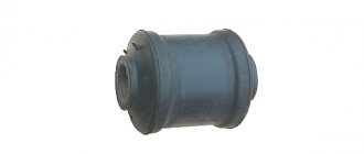
- silent blocks.
The arm with the ball joint and spacer creates a triangle, the two sides of which (the back of the arm and the front of the support) are attached to the body using brackets. Silent blocks are installed in the rear and middle parts of the lever, that is, rubber or polyurethane bushings that ensure free rotation of the parts inserted into them. The back of the lever is inserted into the bracket and secured with a bolt, so the lever moves up and down freely, but does not leave its place.
The extension at the front is fixed with a bracket, which is bolted to the body, and at the back it is inserted into the hole in the middle part of the lever closest to the front edge through a silent block. This design allows you to adjust the castor, that is, the angle of inclination of the stand relative to the vertical axis.
A stabilizer bar is attached to the hole in the lever farthest from the ball joint, which is also equipped with a silent block. The edge of the stabilizer is inserted into the upper part of the rod, equipped with a silent block, and its middle is screwed to the body through shock-absorbing pads.
These elements work as follows: a ball joint connects the lever to the rack, due to which the latter takes on the weight of the machine and rotates freely around its axis. The resistance to up and down movement depends only on the stiffness of the strut, that is, the shock absorber-spring pair.
When both wheels rise or fall at the same time, only the MacPherson strut works, but if the height of the wheels is different, then the stabilizer experiences a torsional effect, and therefore acts as a torsion bar.
That is, the greater the difference in height between the wheels, the more the stabilizer twists, which increases its resistance to torque. Its rigidity is sufficient not only for a quiet ride, but also for cornering at high speeds, because the stronger the centrifugal force deflects the body, the stronger the stabilizer resists this, reducing the roll angle. This is how the front suspension of the VAZ 2115, as well as all other front-wheel drive cars from AvtoVAZ, works.
Rear suspension
The design of the rear suspension of the VAZ 2114 car, as well as other VAZ 2108–2115 cars and their descendants, is much simpler, although the general principle of operation is the same. Its basis is a beam, which performs several functions at once:
- connects wheels and springs with shock absorbers (struts);
- holds the wheels in a certain place, so that they do not catch on the wheel arches;
- reduces lateral roll during turns.
This part is made of relatively thin metal, compared to the anti-roll bar, but due to its shape with stiffening ribs, it turns into a torsion bar with not very high elasticity. When the rear wheels are simultaneously raised or lowered, the beam performs only the function of a lever, forming a triangle with the body and racks, in which:
- one vertex is a bracket with a silent block connecting the beam to the body;
- the second peak is a flange to which both the wheel hub axle and the lower part of the rear pillar are attached;
- the third vertex is the place where the upper part of the rack is attached to the body.
When the Lada drives over an obstacle, the wheel rises and compresses the strut spring, transferring the impact energy to the body through it. As the wheel rises, the spring resistance increases, so that even a sharp blow turns into a smooth rise, and the shock absorber resists any movement, but most strongly when the wheel is lowered. This prevents the wheel from accelerating too much and, having hit the ground, bouncing off it again.
Types of pendants
When driving through an obstacle, the length of one of the sides of the triangle and the angle between the other two sides change, and when the wheels rise to different heights, the rear beam twists. Due to its elasticity, bending resistance increases as the height difference increases, which reduces lateral roll in corners, but it is much less effective than a front-mounted stabilizer.
Disassembling and replacing the front suspension: instructions
- The VAZ 2114 is installed on a viewing hole or raised on a lift. The car must be set to the parking brake. It is necessary to remove the wheel caps, loosen the mounting bolts and unscrew the hub nut. Having secured the front of the car, you can remove the front wheels.
- Next, you need to remove the ball joint pin, which is located in the swing arm of the front strut. The next step is to remove the front stabilizer link (number “24”) from the front suspension arm (number “22”). Next, the stretch marks from the body (30) are removed. Next, you need to completely disconnect the ball joint that is attached to the steering knuckle.
- Now you can remove the front suspension arm. To do this, you need to disconnect it from the body bracket (28). Afterwards the lever is removed along with the bracket and the extension (29, 30). It is also necessary to remove the bolts that secure the pads to the steering knuckle.
- In front of the driver there will be a caliper assembly. To avoid problems with it, you do not need to completely remove it; you need to hang the caliper on a hook in such a way that there is no load on the main hose. The next step is to press the spline shank out of the front wheel hub.
- From the side of the engine compartment, you need to remove the protective fist (“41”). To do this, unscrew the telescopic strut nuts and then remove the solid front suspension strut. It should be together with the wheel hub and steering knuckle. The other front suspension strut is removed in the same way. Next, the racks are removed from the rod.
VAZ chassis repair
The working chassis of the VAZ is a soft ride and excellent handling of the car. To maintain the suspension in excellent condition, we recommend regularly inspecting it at a car service center, since it is in this case that specialists will be able to identify deviations from normal performance at an early stage and, as a result, eliminate the problem that has arisen.
The masters of the Exclusive technical center are experienced professionals in their field. They will be able to do a complete diagnosis and repair of the VAZ running gear. All work is carried out using high-precision equipment, and components are replaced using original spare parts.
About VAZ cars
The largest car manufacturer in Russia. The plant was built on the initiative of the Chairman of the Council of Ministers of the USSR Alexei Kosygin in the 1960s. . Equipment and technologies for it were purchased from the Italian concern Fiat. During the Soviet Union, its model range consisted of the following brands: Zhiguli, Niva, Oka, Sputnik, Samara. Today it produces various modifications of cars under the general name Lada, and also assembles Nissan and Renault cars, since these global brands have a controlling stake in VAZ.
Initially, VAZ cars were designed to saturate the domestic market of the USSR. They were affordable, reliable and easy to repair. At the present stage, these qualities have been supplemented by comfort and ease of operation, thanks to many additional options and modern functional equipment. At the same time, the price remained very affordable.
Types of work when repairing the chassis of a VAZ car
Repair of a VAZ chassis may include the following types of work:
- suspension overhaul
- VAZ beam replacement
- bridge replacement
- replacing axle shaft
- replacing VAZ springs
- replacing the support bearing
- replacing the strut support
- VAZ CV joint replacement
- spring repair
- subframe replacement
- cardan repair
Our car service center on Vasilyevsky Island repairs VAZ chassis of all the following models:
- Lada Kalina 1117/1118/1119
- Lada Samara 2113/2114/2115
- Lada Priora (Lada Priora 2170/2171/2172/21728)
- Lada Granta
- Lada Largus
- VAZ 2104
- VAZ 2105
- VAZ 2106
- VAZ 2107
- VAZ 2108
- VAZ 2109/21099
- VAZ 2110
- VAZ 2111
- VAZ 11113 Oka
- VAZ 2114
- VAZ 2115
When contacting the site, you will receive a 5% discount on your first visit to the service center.
Disassembling and replacing the rear suspension: instructions
A complete disassembly of the rear suspension is required if the motorist decides to lubricate all the parts or change them. Most often you need to get to a specific element and replace it. The parsing proceeds as follows:
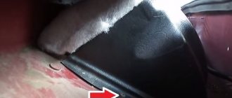
- The VAZ 2114 is installed under an inspection hole, or, as an option, on a lift. In the luggage compartment, the rear and side trims and the seat belt retractor are disconnected. Also in the luggage compartment there are fastenings for the racks to the car body. They need to be loosened; there is no need to unscrew them completely.
- Next, the fastenings of the rear wheel pair are loosened. To do this, you need to remove the hubcaps and then completely dismantle the wheels. Reliable jacks should hold the car at this time; they are usually installed on each side.
- Now it is necessary to dismantle the brake system cables. You need to get them assembled. To do this, the cable fastenings to the suspension arms and the body of the VAZ 2114 are disconnected. Afterwards, the brake drums are dismantled. The cable ends should be removed from the manual drive levers. You also need to disconnect the flanges from the brake flaps.
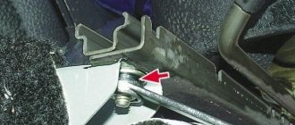
- Before dismantling the hoses and pipes of the brake system, care must be taken to prevent leakage. Next, you need to dismantle the elastic drive lever, which is used to operate the brake pressure regulator. To remove the lever, you need to disconnect it from the bracket by removing the lock washer, then remove the shackle from the wheel axle.
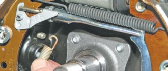
- The next step is to disconnect the struts (shock absorbers). To do this, remove the rubber cushions, nuts attaching to the body part and the washer. After this, you need to install additional stops for the front wheelset. The rear part should be raised. After this, you can remove the compression stroke buffers, springs and shock absorber covers.
- If you disconnect the body mounting brackets, the entire beam can be detached. The rear suspension along with the struts will lie in front of the motorist. If necessary, you can disassemble the shock absorbers, which is no longer difficult.
What's included in the rear suspension?
The image below shows all the main elements of the rear suspension that can fail.
- The first part is a rubber-metal hinge, which is the main attachment to the car body.
- A bracket used to secure the rear suspension arm to the body.
- Shock absorber housing.
- A buffer that takes the load from the compression stroke.
- Casing cover.
- Main support washer.
- Shock-absorbing cushion.
- Spacer sleeve.
- Strut (shock absorber).
- Insulation gasket.
- Solid spring.
- Connecting element for levers.
- Beam lever.
- Bracket for fastening the rack structure.
- Flange.
- Lever bushing.
The beam structure includes a connector and two trailing arms; these elements are indicated in the diagram as numbers “12” and “13”. The parts are fastened together by welding. In the rear part, flanges (number “15”) and brackets for attaching struts (shock absorbers) are attached to the levers. The axles of the rear pair of wheels along with the brake elements are screwed to the flanges. Bushings (16) are installed on the rear suspension arms at the front. They are fastened using rubber-metal hinges - number “1”. One end of the spring rests on the support through a rubber gasket, and the other on the shock-absorbing cup.
What's included in the front suspension?
The front suspension of the VAZ-2114 consists of many elements, but many motorists have encountered repairing them individually, and not as a whole system. The front suspension assembly is replaced if the car is involved in a traffic accident and almost all of its elements are destroyed.
So, it’s worth considering what the car’s front suspension consists of, to see what elements are included.
Vehicle suspension device
Design and decoding of VAZ-2114 suspension elements:
1 – upper support of the telescopic stand; 2 – upper support cup; 3 – compression stroke buffer with protective casing; 4 – compression buffer support; 5 – suspension spring; 6 – lower spring support cup; 7 – steering rod ball joint; 8 – steering knuckle; 9 – telescopic stand; 10 – eccentric washer; 11 – adjusting bolt; 12 – rack bracket; 13 – steering knuckle; 14 – front brake protective cover; 15 – brake disc; 16 – retaining ring; 17 – wheel hub nut; 18 – splined shank of the wheel drive hinge housing; 19 – guide pin; 20 – wheel hub bearing; 21 – ball joint; 22 – suspension arm; 23 – adjusting washers; 24 – stabilizer strut; 25 – stabilizer bar; 26 – stabilizer bar cushion; 27 – stabilizer bar mounting bracket; 28 – body bracket for mounting the suspension arm; 29 – suspension arm extension; 30 – bracket for fastening the extension; 31 – protective cover of the ball pin; 32 – ball pin bearing; 33 – ball pin; 34 – ball pin body; 35 – suspension strut rod; 36 – outer body of the upper support; 37 – inner body of the upper support; 38 – upper support bearing; 39 – rubber element of the upper support; 40 – travel limiter of the upper support; 41 – protective cap of the upper support; B - zone for monitoring the suspension joint.
Individual elements of the front suspension
Front suspension elements
Front suspension view from below
As can be seen from the figure above, the suspension is quite simple, but all elements are interconnected and for repair and replacement, it is often necessary to disconnect other parts. Therefore, we will consider the main elements of the front suspension separately, and also indicate the main purpose of the part.
Front shock absorber strut
Front shock absorbers
The front shock absorber or front suspension strut is one of the main elements. This part provides shock absorption and absorption of uneven road surfaces. Also, it bears all the force that is in the car, including the load.
Usually, if this element is frequently loaded or incorrectly replaced, it has an increased degree of wear. Therefore, all motorists need to know the structure and operating rules of the shock absorber strut.
Let's look at how the shock absorber strut is designed, as well as all the structural elements:
Diagram of the shock absorber strut structure
1 – compression valve body; 2 – compression valve discs; 3 – throttle disk of the compression valve; 4 – compression valve plate; 5 – compression valve spring; 6 – compression valve cage; 7 – recoil valve nut; 8 – recoil valve spring; 9 – recoil valve plate; 10 – recoil valve disc; 11 – throttle disk of the recoil valve; 12 – piston; 13 – bypass valve plate; 14 – bypass valve spring; 15 – plunger; 16 – plunger spring; 17 – rod guide bushing with a fluoroplastic layer; 18 – guide bushing cage; 19 – sealing ring of the rack housing; 20 – rod seal; 21 – oil seal cage; 22 – gasket of the rod protective ring; 23 – rod protective ring; 24 – nut of the strut body; 25 – compression buffer support; 26 – rod; 27 – spring cup; 28 – rotary lever; 29 – rod limit sleeve; 30 – rack body; 31 – cylinder; 32 – drain tube.
Front stabilizer
A stabilizer is a suspension element that provides lateral stability while driving, especially when turning . This part is the least likely to fail.
Repair manual for the suspension of a Lada 2113 car, eliminating noise and knocking in the suspension of a Lada 2114, replacing the strut of a VAZ 2113, VAZ 2115, VAZ 2114. Checking and repairing the chassis of a VAZ 2115 with your own hands. Description of the running gear of fret 2113. Operation of the front and rear suspension of fret 2114.
The front suspension of the Lada Samara 2 is independent, telescopic, with hydraulic shock absorber struts, coil springs, lower wishbones with braces and a stabilizer bar.
VAZ 2115 front suspension assembly: 1 – upper support of the telescopic strut; 2 – upper support cup; 3 – compression stroke buffer with protective casing; 4 – compression buffer support; 5 – suspension spring; 6 – lower spring support cup; 7 – steering rod ball joint; 8 – steering knuckle; 9 – telescopic stand; 10 – eccentric washer; 11 – adjusting bolt; 12 – rack bracket; 13 – steering knuckle; 14 – front brake protective cover; 15 – brake disc; 16 – retaining ring; 17 – wheel hub nut; 18 – splined shank of the wheel drive hinge housing; 19 – guide pin; 20 – wheel hub bearing; 21 – ball joint; 22 – suspension arm; 23 – adjusting washers; 24 – stabilizer strut; 25 – stabilizer bar; 26 – stabilizer bar cushion; 27 – stabilizer bar mounting bracket; 28 – body bracket for mounting the suspension arm; 29 – suspension arm extension; 30 – bracket for fastening the extension; 31 – protective cover of the ball pin; 32 – ball pin bearing; 33 – ball pin; 34 – ball pin body; 35 – suspension strut rod; 36 – outer body of the upper support; 37 – inner body of the upper support; 38 – upper support bearing; 39 – rubber element of the upper support; 40 – travel limiter of the upper support; 41 – protective cap of the upper support; B - zone for monitoring the suspension joint
The main element of the suspension of the VAZ 2114, VAZ 2115, VAZ 2113 is a telescopic, hydraulic shock absorber strut 9, the lower part of which is connected to the steering knuckle 13 with two bolts. The upper bolt 11, passing through the oval hole of the strut bracket, has an eccentric collar and an eccentric washer 10. When the upper bolt is turned, the camber of the front wheels changes. The following are installed on the telescopic rack: a coil spring 5, a polyurethane foam buffer 3 compression strokes, as well as the upper support 1 of the rack assembled with a bearing 38.
Telescopic strut VAZ 2114: 1 – compression valve body; 2 – compression valve discs; 3 – throttle disk of the compression valve; 4 – compression valve plate; 5 – compression valve spring; 6 – compression valve cage; 7 – recoil valve nut; 8 – recoil valve spring; 9 – recoil valve plate; 10 – recoil valve disc; 11 – throttle disk of the recoil valve; 12 – piston; 13 – bypass valve plate; 14 – bypass valve spring; 15 – plunger; 16 – plunger spring; 17 – rod guide bushing with a fluoroplastic layer; 18 – guide bushing cage; 19 – sealing ring of the rack housing; 20 – rod seal; 21 – oil seal cage; 22 – gasket of the rod protective ring; 23 – rod protective ring; 24 – nut of the strut body; 25 – compression buffer support; 26 – rod; 27 – spring cup; 28 – rotary lever; 29 – rod limit sleeve; 30 – rack body; 31 – cylinder; 32 – drain tube
The upper support of the VAZ 2113 is attached with three self-locking nuts to the body mudguard strut. Due to its elasticity, the support ensures that the strut “swings” during suspension movements and dampens high-frequency vibrations. A bearing built into it allows the rack to turn along with the steered wheels. Parts of a telescopic hydraulic shock absorber are mounted in the strut housing. A hydraulic recoil stroke buffer is installed in the upper part of the cylinder, consisting of a plunger 15 and a spring 16. It limits the movement of the rod during the recoil stroke. The lower part of the steering knuckle 13 is connected by a ball joint 21 to the wishbone 22 of the suspension. Braking and traction forces are perceived by longitudinal braces 29, which are connected through rubber-metal hinges to transverse arms 22 and brackets 30. At the junction of the brace with the lever of the VAZ 2113, VAZ 2114, VAZ 2115 and the bracket, adjusting washers 23 are installed, which adjust the angle of the longitudinal inclination of the axis turn. A double-row angular contact bearing 20 of a closed type is mounted in the steering knuckle, on the inner rings of which the wheel hub is mounted with interference. The bearing is tightened with a nut 17 on the shank 18 of the outer wheel drive joint housing and is not adjustable. All front and rear wheel hub nuts are the same and have right-hand threads. The anti-roll bar is a bar 25, the knees of which are connected to the transverse arms 22 of the suspension through drains 24 with rubber and rubber-metal hinges. The middle (torsion) part of the rod is attached to the body with brackets 27 through rubber pads.
Detailed suspension repair diagram
In order to disassemble the suspension you will need quite a lot of tools: a set of keys and sockets, hammers, crowbars, pullers, and also screwdrivers.
So, let's look at a brief diagram of how to disassemble the suspension of a VAZ-2114 car:
- The car must be placed on a lift. Of course, you can use the inspection hole, but this is quite inconvenient and not entirely safe, since dismantling will be carried out on both sides at the same time.
- The first step is to dismantle the caps (if any), disks and loosen the wheel bearing fastenings.
- Next, disconnect the ball joint and also remove the steering rod.
- Unscrew the fastening and remove the stabilizer.
- The next step is to dismantle the lever.
- We remove the caliper.
- We remove the outer CV joint from the hub.
- Now you can remove the brake drum from the steering knuckle mountings.
- We dismantle the steering knuckle.
- Remove the shock absorber strut assembly.
- We disassemble the removed parts.
- Assembly is carried out in reverse order.
Thus, the entire suspension assembly can be replaced. If we take time, then complete disassembly of the VAZ-2114 suspension will take approximately 8-12 hours, if no difficulties arise. Some “kulibins” make it easier to speed up the process, and if the suspension to be removed will no longer be installed. It is worth noting that this method is dangerous and contrary to safety regulations, especially if the motorist has never performed this process. Let's briefly look at how the accelerated process occurs:
- Unscrew the stabilizer.
- We dismantle the upper mount of the shock absorber struts.
- Unscrew the steering rod and brake hoses.
- Carefully unscrew the lever mount.
- The suspension feeds downwards in the assembly.
Tuning
Tuning suspension for VAZ-2114
Many motorists, in order to improve the stability and maneuverability of the car, install a sports version of the suspension, both rear and front.
and “DVT-sport” offer a complete version of the front chassis assembly of the sports version. This kit is specially designed for the 2108-21099 and 2113-2115 car families.
It fits perfectly into the seats and is attached to the body without requiring any modifications. The sports suspension has greater stability and maneuverability, and can also withstand a load on the suspension that is 2 times greater than the standard one. The cost of this option is about 30-40 thousand rubles.
Tuning suspension installed on a car
Chassis of VAZ 2115 Lada
- Repair manuals
- Repair manual for VAZ 2115 (Samara 2) 1997+.
- Chassis
4.0 Chassis Front suspension Features of the device Possible malfunctions, their causes and methods of elimination Determining the technical condition of suspension parts on the car Checking and adjusting the wheel alignment angles Removing and installing the front suspension Checking the telescopic...
4.1. Front suspension (Category). See the list of materials inside...
4.2. Rear suspension (Category). See the list of materials inside...
↓ Comments ↓
1. General information
1.0 General data 1.1 Technical characteristics of vehicles 1.2. Vehicle controls 1.3. Vehicle operation 1.4 Vehicle maintenance
2. Engine
2.1 Possible malfunctions, their causes and methods of elimination 2.2 Removal and installation of the power unit 2.3 Disassembly and assembly of the power unit 2.4 Disassembling the engine 2.5 Assembling the engine 2.6 Running in the engine after repair 2.7 Checking the engine on the car after repair 2.8. Cylinder block 2.9. Connecting rod and piston group 2.10. Crankshaft and flywheel 2.11. Cylinder head 2.12. Camshaft and its drive 2.13. Lubrication system 2.14. Cooling system 2.15. Supply system
3. Transmission
3.0 Transmission 3.1. Clutch 3.2. Gearbox 3.3. Front wheel drive
4. Chassis
4.0 Chassis 4.1. Front suspension 4.2. Rear suspension
5. Steering
5.0 Steering 5.1. Features of the device 5.2 Possible malfunctions, their causes and methods of elimination 5.3 Inspection and testing of the steering control of the car 5.4. Removal and installation 5.5 Checking the gap between the rack stop and the nut 5.6. Disassembly, technical condition check and assembly 5.7 Replacing the rivets of the elastic coupling of the steering shaft
6. Brake system
6.0 Brake system 6.1. Features of the device 6.2 Possible malfunctions, their causes and methods of elimination 6.3. Checking and adjusting brakes 6.4. Vacuum booster 6.5. Main cylinder 6.6. Pressure regulator 6.7. Front wheel brake 6.8. Rear wheel brake 6.9. Dismantling and assembling wheel cylinders 6.10. Parking brake system
7. Electrical equipment
7.0 Electrical equipment 7.1. Wires and fuses 7.2. Battery 7.3. Generator 7.4. Starter 7.5. Lighting and light signaling 7.6 Sound signal 7.7. Windshield cleaner 7.8. Heater fan electric motor 7.9. Electric motor of the engine cooling system fan 7.10. Instrument cluster 7.11. On-board control system display unit 7.14. Electric windows and front door lifts 7.15. Door lock system
8. Body
8.0 Body 8.1. Device Features 8.2. Body frame repair 8.3. Paint and varnish coatings 8.4. Anti-corrosion protection of the body 8.5 Sealing of the body 8.6. Doors 8.7. Hood, trunk lid, bumpers 8.8. Body glazing 8.9. Instrument panel, seats 8.10. Heater
9. Cars VAZ-2115-01, VAZ-2114-20
9.0 Cars VAZ-2115-01, VAZ-2114-20 9.1. Car VAZ-2115-01 9.2. Car VAZ-2114-20
10. Applications
10.0 Appendices 10.1 Appendix 1. Tightening torques for threaded connections 10.2 Appendix 2. Special tools for repair and maintenance 10.3 Appendix 3. Basic data for adjustments and monitoring 10.4 Appendix 4. Fuels and lubricants and operating fluids
conclusions
The installation and repair of the front suspension of the VAZ-2114 is quite difficult and not every motorist can do it. This article examined the design and repair of the front suspension.
As you can see, there is a main group of parts that change when worn out and broken, and there are also a number of parts that are considered consumables and are replaced when the main components are repaired.
It is worth noting that suspension repair has a significant degree of danger, because the fall of one of the elements can lead to injury and even death. Therefore, when performing repair operations you must be extremely careful. Also, many suspension elements are quite heavy, so you need to have an assistant on hand.
Source