Repairing the cylinder head (cylinder head) is a necessary measure associated with a malfunction of the internal combustion engine. Symptoms of malfunction:
- Smokes
- Eats oil
- Doesn't start on first crank with starter
- The engine won't start
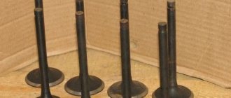
- Due to valve breakage
Repair of the cylinder head is carried out after accurately establishing the cause of the malfunction, which can be determined by diagnostic methods, both on the carburetor engine and on the injector.
On a car, the same malfunction can be caused by different reasons. For example, if the engine begins to run intermittently or is tripping, this does not mean that the culprit of the malfunction is the cylinder head. Repair is an expensive operation and therefore first of all it is necessary to determine:
- whether the spark plugs, high-voltage wires and ignition coil work correctly;
- serviceability of fuel injectors;
- presence of a switching signal at the connectors of the injectors and ignition coil;
- whether the fuel pump provides the required fuel pressure in the rail.
If there are no malfunctions in the injection engine control system, you can begin to repair the cylinder head.
Next, let's look at the example of the 8-valve engine of the VAZ family of cars: 2108, 2109, 2110, 2111, 2113, 2114, 2115, Granta, Kalina, Priora, and the basics of repairing the cylinder head.
Cylinder head repair process
Dismantling
On cars with 8 cl engines, the cylinder heads are the same type and interchangeable. Accordingly, all mechanics of actions are carried out regardless of the car model using a single repair technology. When starting to dismantle the cylinder head, general preparation of the vehicle and tools is carried out. The first necessary action is to disconnect the on-board electrical network from the battery. To do this, simply remove the negative terminal from the battery. The second action is aimed at carrying out work related to draining the coolant from the cylinder block by unscrewing the plug located between the third and fourth cylinders. There is no need to drain the fluid from the radiator.
Remove the air filter housing with the rubber pipe by unscrewing the clamp on the throttle assembly. Disconnect the fuel lines from the injector rail.
Disconnect the throttle control cable from the throttle assembly.
Unscrew the two valve cover nuts and remove it. The valve cover gasket must be replaced with a new one during assembly.
After carrying out the general preparatory work, we proceed directly to disassembling the parts and assemblies that prevent the final lifting of the head from the cylinder block.
Unscrew the three bolts of the timing belt mechanism protective cover and remove the cover.
Set the piston of the first cylinder to the top dead center position, while the mark on the camshaft gear should be located opposite the bent bracket of the cover housing.
Fix the position of the crankshaft with a special comb through the inspection hole on the flywheel housing.
Unscrew the nut holding the timing belt tensioner pulley and remove it with a set of washers.
Remove the belt from the camshaft gear and pump and move it to the side.
While holding the camshaft, unscrew the bolt from the gear and remove it.
Unscrew the bolts securing the reflector to the cylinder head housing and cylinder block and remove it together with the pump.
Next, you need to unscrew the two nuts and bolt from the side camshaft cover and remove it, as well as remove the thermostat housing, which is mounted on studs.
Unscrew the nuts securing the upper camshaft bed covers. Remove the covers and camshaft.
Unscrew all the nuts securing the exhaust and intake manifolds and separate them from the head towards the windshield.
The cylinder head mounting bolts are most often made with a Torx key (Torx External). The head of such a bolt has the shape of a six-pointed star and its use is based on the purpose of reducing its size.
Depressurization of valves
Structurally, in the cylinder head, the valve stem passes through a guide pressed into the body of the head. The operation of the valve mechanism is ensured by sequentially assembled parts: lower spring seat, valve stem seal, external spring, internal spring, upper cone seat, retaining nuts.
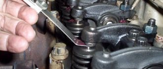
For further work related to replacing the valve or seat, pressing out the guide bushing, the unit must be disassembled. It is not difficult to carry out the disassembly operation if you have a “dehumidifier” device, which is a system of levers. The end point of the lever is attached to the supporting surface, and the middle part rests with a ring on the upper spring seat. By applying pressure on the spring seat with a lever, access to cone-shaped crackers is opened, which are removed with tweezers.
If you perform desiccation with your own hands and do not have a device, this action can be performed with a hammer blow, having previously selected the mandrel to the size of the upper spring seat.
Replacing guides
Valve guides must be replaced if the permissible runout is exceeded, which is no more than 0.6 mm for exhaust valves, and no more than 0.4 mm for intake valves.
The runout is checked using special equipment consisting of a massive plate, which is mounted on the head surface that has already been prepared on a milling machine. A tripod allows you to hold the micrometer in the desired position by moving it vertically and horizontally. Having deflected the valve, inserted into the guide in the direction of movement of the rod until it stops, bring the working head of the micrometer until it touches the valve plate. The arrow on the micrometer is set to zero by rotating the scale and the valve is deflected towards the movement of the micrometer rod. The arrow readings should not exceed 40 divisions for the inlet valve and 60 divisions for the exhaust valve.
If the permissible standards are exceeded, the guide is pressed out with a special drift and a new one is pressed in as well. Then it is processed with sweeps.
It should be borne in mind that the guide for the exhaust valve on the inner surface has a heat-dissipating thread along its entire length, and the intake valve only up to half the length.
Countersink
When installing a new valve guide, the centerline of the valve guide will in most cases not be aligned with the center axis of the seat. To restore the alignment and tight fit of the valve plate to the seat, its edges are processed with special cutters that have three chamfer angles:
- upper correction angle – 300
- valve seat angle - 450
- lower correction angle - 600
A set of cutters for countersinking intake and exhaust valves and mandrels for them can be purchased at specialized retail chains.
Lapping
Lapping of the seat-valve pair is performed to obtain a tight seal. Lapping is carried out using a drill, a manual collet lever equipped with a return spring, or a pneumatic device with a set of suction cups of different sizes. A composition of grinding powder and motor oil is used as an abrasive, or ready-made lapping pastes are used.
Before grinding, you need to lubricate the valve stem with oil and install the valve in the guide. Then prepare the device and, lifting the valve plate above the seat, place lapping paste along the edge of the plate.
By performing rotational movements around the valve axis in combination with reciprocating movements, the valve is ground into the seat. The appearance of a matte gray belt on the seat chamfer indicates the quality of the surfaces being ground.
Leak test
Upon completion of the grinding operation, finally check the quality of the seal with kerosene with the valves closed. If a kerosene leak is not detected after holding for 2-3 hours, then the cylinder head can be finally assembled. If a leak is detected, the grinding operation should be repeated.
Replacing valve stem seals
Replacement of valve stem seals is mandatory when repairing the cylinder head. During engine operation, options are possible when a defective oil seal (oil seal) flies off the top of the valve guide and moves freely along its rod. A symptom of a malfunction associated with the valve stem seal is the appearance of smoke from the muffler during re-gassing and a slight drop in the oil level in the crankcase. If a malfunction occurs during engine operation, the valve stem seals can be replaced without removing the cylinder head from the engine. It is enough to disassemble the valve cover and remove the camshaft.
Dry out the valve assembly, remove the springs and remove the damaged caps with a special tool (puller pliers, impact collet).
Lubricate the new caps with oil and press them lightly with a hammer through a special mandrel onto the upper part of the guide.
Reassemble the valve assembly and camshaft in reverse order and adjust the valve clearances.
Replacing the cylinder head gasket
During repairs or in case of damage to the cylinder head gasket, it is necessary to remove the head from the engine. The working part of the surface must be leveled by grinding (this is done more efficiently on a milling machine). Clean the mating surface of the cylinder block from traces of the old gasket, blow air to remove particles and dust, as well as the threaded wells for the bolts securing the head.
Place a new gasket on the surface of the cylinder block and perform installation in the reverse order.
VAZ cylinder head assembly
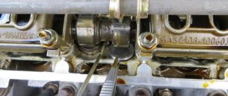
Assembling the cylinder head must begin after thoroughly purging the surface from foreign objects and particles. Pay special attention to the cleanliness of the internal surfaces of the valve guides and oil supply channels on the camshaft beds. Lubricate the camshaft seats and oil seal, valve stems, tappets and valve stem seals with engine oil.
Insert the valves into the guides (each valve, after grinding in, strictly belongs to the corresponding cylinder). Orient the cylinder head on the table for assembling the valve assemblies and place the lower spring washers. Using a special impact mandrel, press in the valve stem seals and continue assembling the outer and inner springs. Place the upper conical washers on the springs and install the crackers - clamps - with a special tool - a desiccant tool.
The next stage of assembly is the installation of pushers, which, like valves, are inserted in strict accordance with the corresponding cylinder. The final step in assembling the cylinder head is installing the camshaft. The camshaft along with the oil seal is placed on the bed and the covers are placed on top. A thin layer of sealant is first applied to the extreme points of contact with the cylinder head surface. The covers are tightened with nuts and the head is ready for installation on the engine.
Is camshaft seal needed? This is a question that novice motorists ask. Rubber parts, if they are of good quality, do not require additional use of sealant.
Mounting on cylinder block
Before installation, it is necessary to clean and blow with compressed air the surface of the cylinder block from foreign particles, dust, drops of oil and antifreeze.
Place the cylinder head gasket on the surface of the cylinder block and carefully install the head, monitoring its position along the fixing bushings.
Next, the head mounting bolts are installed and 4 stages of tightening are done with a torque wrench:
- 20 N*m.
- 85.7 N*m
- 90°
- 90°
Pulling scheme
The following stages of installation are performed according to the technological process diagram in the reverse order of disassembly described above.
Characteristics of motors 2114
Since the release of the Lada Samara VAZ-2114, the technical characteristics of the gasoline drive have been constantly improved. Owners of domestic cars, in principle, do not have questions about what kind of oil to pour into the engine, since standard requirements apply for Zhiguli, Lada and Samara - 5W30 or 10W30.
In addition, you should know what kind of oil to use in transmission gears - the instructions from the AvtoVAZ manufacturer recommend using the GL-4 group of lubricants with a viscosity of 80W85 (mineral), 75W90T (synthetic) or 85W90 (semi-synthetic).
After filling with synthetics, the box becomes noisy, the oil is more expensive, but the lubricant is mostly imported, which provides additional guarantees. Domestic manufacturers most often produce semi-synthetics of average quality for engines and transmission gearboxes.
The technical characteristics of the engine are as follows:
| Characteristics | Engine modification | ||||||||
| 2111 | 21114 | 11183 | 21124 | 21126 | |||||
| Years of installation | 2003 – 2007 | 2003 – 2007 | 2007 – 2009 | 2009 – 2013 | 2009 – 2013 | ||||
| Volume | 1500 cm 3 (97.9 hp) | ||||||||
| Torque moment | 115.7 Nm (3200 rpm) | 125 Nm (3000 rpm) | 120 Nm (3200 rpm) | 131 Nm (3700 rpm) | 145 Nm (4000 rpm) | ||||
| Weight | 127.3 kg | 112 kg | 112 kg | 121 kg | 115 kg | ||||
| Compression ratio | 9,8 | 9,6 | 9,6 | 10,3 | 11 | ||||
| Nutrition | injector | ||||||||
| Engine diagram | Inline (L) | ||||||||
| Ignition | module | coil | coil | coil for each spark plug | |||||
| Number of cylinders | 4 | ||||||||
| Location of the first cylinder | TVE | ||||||||
| Number of valves on each cylinder | 2 | 2 | 2 | 4 | 4 | ||||
| Cylinder head material | aluminum alloy | ||||||||
| Intake manifold | aluminum | plastic with receiver | |||||||
| An exhaust manifold | with catalyst | ||||||||
| Camshaft | 2110 | 2111 | 2112 | ||||||
| Cylinder diameter | 82 mm | ||||||||
| Piston stroke | 71 mm | 75.6 mm | |||||||
| Pistons | Yes | No | No | Yes | No | ||||
| Valve bend | Yes | No | No | Yes | No | ||||
| Crankshaft | 2112 | 11183 | |||||||
| Fuel | AI-95 | ||||||||
| Environmental standards | Euro 4 | Euro 2 – 4 | Euro 3 – 4 | ||||||
| Fuel consumption highway/combined cycle/city | 5,7/7,3/10 | 6/7,3/10,4 | 6/7,8/11 | 5/7/9,5 | 5,4/7,2/9,8 | ||||
| Oil consumption per 1000 km | 0,7 | 0,5 | |||||||
| Engine oil for 2114 | 5W-30 and 10W-30 | ||||||||
| Engine oil volume | 4 l | 3.8 l | 3.5 l | 3.6 l | |||||
| Operating temperature | 95° | ||||||||
| Motor life | declared 150,000 km, real 250,000 km | ||||||||
| Adjustment of valves | washers between camshaft cams and tappets | hydraulic pushers | |||||||
| Cooling system | forced, antifreeze/antifreeze | ||||||||
| Coolant quantity | 7.8 l | ||||||||
| water pump | plastic impeller | ||||||||
| Candles for 2114 | A17DVRM, BPR6ES | AU17DVRM, BCPR6ES | |||||||
| Gap between spark plug electrodes | 1.1 mm | ||||||||
| Timing belt | length 698 – 1125 mm depending on attachments | ||||||||
| Cylinder operating order | 1-3-4-2 | ||||||||
| Air filter | Nitto, Knecht, Fram, WIX, Hengst | ||||||||
| Oil filter | Mann W914/2 | ||||||||
| Flywheel | 2110 | ||||||||
| Flywheel mounting bolts | M10x1.25 mm, length 26 mm | ||||||||
| Valve stem seals | code 90913-02090 inlet light code 90913-02088 exhaust dark | ||||||||
| Compression | from 14 bar | ||||||||
| XX speed | 750 – 800 | 800 – 850 | |||||||
| Tightening force of threaded connections | spark plug – 31 – 39 Nm clutch bolt – 54 – 87 Nm bearing cap – 59 Nm (main) and 43 – 53 Nm (rod) cylinder head – four stages 20 Nm, 71 Nm + 90° + 90° | ||||||||
For high-quality maintenance of internal combustion engines, the engine manufacturer issues a manual containing a description of the drive parameters, the frequency of replacing consumables and step-by-step repair operations. The same operating manual recommends the volume of oil in the gearboxes in the engine.
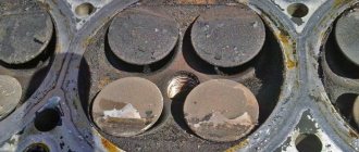
Replacing valve seats
If the seats burn out and are destroyed, as well as if the heads are strongly recessed into the body (“sucked”) or have been subjected to repeated countersinking, they need to be replaced. The seats are replaced on a milling machine. The defective seat is bored with a milling cutter and removed from the socket. Then, according to the technology, the head is placed in a thermal oven and heated to 120-150 degrees. Saddle blanks in the form of rings are placed in liquid nitrogen to reduce their temperature to minus 40 degrees. Using tongs, place the cooled rings of future saddles into the sockets and lightly tap them into the body of the head. Further operations for processing seat chamfers are performed on a special milling machine or manually with a set of cutters.
Maintenance schedule
To avoid having to carry out expensive overhauls of the Lada Samara 2114 yourself, you should follow the manufacturer’s recommendations for servicing the internal combustion engine:
| Maintenance object | Time or mileage (whichever comes first) |
| Timing belt | replacement after 100,000 km |
| Battery | 1 year/20000 |
| Valve clearance | 2 years/20000 |
| Crankcase ventilation | 2 years/20000 |
| Belts that drive attachments | 2 years/20000 |
| Fuel line and tank cap | 2 years/40000 |
| Motor oil | 1 year/10000 |
| Oil filter | 1 year/10000 |
| Air filter | 1 – 2 years/40000 |
| Fuel filter | 4 years/40000 |
| Heating/Cooling Fittings and Hoses | 2 years/40000 |
| Coolant | 2 years/40000 |
| Oxygen sensor | 100000 |
| Spark plug | 1 – 2 years/20000 |
| Exhaust manifold | 1 year |
If consumables are replaced within the recommended time frame, the operational life of the internal combustion engine will increase.
Features of repairing the cylinder head of the Lada Granta
The engine of the Lada Granta car has differences with the Kalina engine. The block head, in comparison with the Kalinovskaya one, has been increased in height by 1.2 mm. This is due to a change in the combustion chamber. Lightweight pistons installed. The timing belt has been modified and operates in a temperature range from minus 40 to plus 40 degrees. The declared belt mileage is up to 200 thousand kilometers.
The main feature of Granta cylinder head repair is the use of metal-ceramic seats. By car Kalina, 2114, etc. Cast iron saddles are used, which can be processed manually using a set of domestic cutters.
Machining cermet seats requires wear-resistant cutting tools. In order to successfully process them, the head is installed on the NEWENContour - BB machine, designed specifically for the rapid processing of seats and valve guides with digital control or manually with a Neway tool.
Cons and pros
Depending on which 2114 engine is used, the owner’s risks differ:
- 2111, 21183, 21114 and 21124 – do not bend the valve if the timing belt breaks;
- 21126 – valve bending due to insufficient groove.
The main disadvantage of the latest 16 valve versions is the lighter crank mechanism:
- the engine is adjusted to Euro-4 standards;
- to reduce weight, the length of the piston skirt is reduced;
- Accordingly, the width of the oil scraper and compression rings decreases;
- The resource of the internal combustion engine is sharply reduced.
For example, in Japan, manufacturers abandoned Euro-4 standards, considering that the reliability and high service life of the motor are more important for the consumer.
The drive power increased from 77 horsepower to 81 hp, then 82 hp, 89 hp, and 98 hp. In models with hydraulic compensators, periodic adjustment of this unit is not required, however, the quality of the oil in the system must be high for normal operation of the pushers.
Malfunctions after cylinder head repair or gasket replacement
The car won't start
If the car does not start after replacing the gasket, it is necessary to check the presence of a spark on the spark plugs and the fuel pressure in the rail. Make sure that there is no air leak through the fitting on the receiver intended for the vacuum brake booster tube.
Engine troubles
Just as with a major overhaul of the head, replacing the cylinder head gasket involves removing the head and, accordingly, disconnecting the connectors from the sensors, removing high-voltage wires, tubes connected to the intake manifold (receiver) from the vacuum brake booster, adsorber, and fuel pressure regulator.
If the engine stalls after installing the cylinder head, it is necessary to check all electrical connections and the presence of air leaks, as well as the thermal clearances of the timing valves. Rehabilitation after valve replacement usually lasts for 500 km, but there may be cases when, after the first start, it is necessary to adjust the thermal clearances.
A malfunction associated with engine tripping after repair may also be temporary, since the spark plugs may be wet and after several starts, thanks to purging and calcination, the engine begins to run smoothly.
The engine smokes
After replacing the gasket, the engine smokes as the temperature increases. This situation is quite normal. The antifreeze is drained, during disassembly, engine oil gets onto the surface of the engine, and as the engine heats up, all these liquids evaporate, causing smoke.
Burns oil after valve replacement
The valve stem seals were replaced without removing the cylinder head. It is possible that the valve stem seals are defective or damaged during pressing with a faulty mandrel.
No compression after valve replacement
After replacing the valves, it is recommended to warm up the internal combustion engine and measure the compression. If low compression is detected in one or more cylinders, check and adjust the valve clearances. If there is no compression in all cylinders and it is zero, then it is necessary to remove the cylinder head in order to inspect the integrity of the gas distribution mechanism parts and, if necessary, carry out a comprehensive engine repair.
Tightening torque of the cylinder head VAZ 2114 8 valves: correct operation with a torque wrench
A tool such as a torque wrench, which allows you to tighten bolts with equal force, requires great care in operation and certain skills.
Torque wrench
An approximate sequence for tightening bolts with this wrench is as follows:
- set the holder to the “zero” position;
- begin smooth rotation of the instrument, while simultaneously monitoring its readings;
- if the tool rotates (especially at the initial stage of tightening) without changing the torque on the indicator, this may indicate a slight internal stretch of the fasteners. This phenomenon is absolutely normal and the rotation of the tool should be continued;
- When the tightening torque corresponding to the required one is reached, the movement of the tool should be stopped.
Bolt tightening
Instead of using a torque wrench, you should not use any other tool (including a mechanized one, with the ability to regulate the tightening force). After all, only with a wrench can you achieve absolutely precise and smooth tightening of the bolts, thanks to which the gasket will be evenly pressed over the entire surface of the block. This will help maximize its service life, avoid burnouts, oil leaks and coolant leakage.
Removal
1. Prepare the car for work and disconnect the wire terminal from the negative terminal of the battery (see “Preparing the car for maintenance and repair”).
2. Drain the coolant from the engine (see “Coolant - replacement”).
4. Remove the intake pipe and exhaust manifold from the engine (see “Lasing the intake pipe and exhaust manifold - replacement”).
Note: If necessary, the cylinder head can be removed complete with parts of the power system and exhaust manifold.
6. On engines with phased fuel injection
disconnect the wire connector from the camshaft position sensor (see “Camshaft position sensor - check and replacement”).
7. Disconnect the wire tips from the coolant temperature sensor (see “Coolant temperature sensor - check and replacement”). For ease of operation, disconnect the wiring harness block from the knock sensor (see “Knock sensor - checking and replacement”) and move the sensor wiring harness to the side.
8. Disconnect the wire tip from the coolant temperature indicator sensor (see “Coolant temperature indicator sensor - check and replacement”).
13 mm socket wrench
Unscrew the nut securing the “mass” wire to the engine and remove the wire tip from the stud.
13 mm socket wrench
Unscrew the two nuts securing the pipe.
11. Remove the pipe from the cylinder head studs and, without disconnecting the hoses, move it to the side.
12. Remove the sealing gasket from the studs.
14. Unscrew the nut and bolt of the upper fastening of the rear timing belt cover (see “Coolant pump - replacement”).
15. Remove the oil level indicator.
Torx E14 socket wrench
with a narrow head, unscrew the ten bolts securing the cylinder head.
Tip: Some of the cylinder head bolts can only be unscrewed with a socket wrench with a narrow head. If you do not have such a key, remove the camshaft (see “Camshaft - removal and installation”) and then unscrew the cylinder head bolts.
17. Pulling the rear timing belt cover slightly to the side, remove the cylinder head.
18. Remove the cylinder head gasket.
19. We take out two guide bushings.
Typical breakdowns
The very first 1.5 liter engine 2114 has disadvantages:
- periodic valve adjustment;
- unreliable injection system;
- loosening the exhaust manifold nuts;
- Leaking gaskets of the fuel pump, distribution sensor of the ignition system.
The next 1.6 liter engine does not cause any particular problems for the owner, with the exception of high vibration and noise loads. The weak point traditionally remains the valves, which have to be constantly adjusted.
The internal combustion engine from Lada Kalina 11183 was installed on the fourteenth model solely to meet Euro-3 standards. It has typical disadvantages for a linear series and is no different.
The first sixteen-valve engine 21124 does not bend the valves, the gaps in which are adjusted by hydraulic pushers. However, the belt needs to be tightened after 15,000 km due to the large number of attachments. The second and last in the line of fourteenth ICE models, ICE 21126, has increased power. In addition to typical malfunctions, if the timing belt breaks, the piston will bend the valve due to insufficient recess depth.
Necessary tool
To carry out the work, we will need to have the right tool to do it correctly:
- Set of heads;
- Extensions;
- Driver or ratchet;
- Torque wrench.
The complexity of the process is that we will need to find or purchase the last key. Its price starts from 2000 for the simplest one. If you frequently repair your vehicle, this wrench will be a great addition to your garage as it is essential in many processes that require precise bolt tightening.
Useful : 7 reasons why the engine on a VAZ 2114 gets hot?
Method 1 - bolt shrinkage
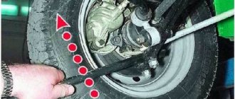
Suitable for VAZ 2107 (other classic models), as well as cars where the cylinder head is secured with bolts to the outer edges. On models of the 2108 series and higher, this method is also acceptable, but at a certain stage of the work there you will have to resort to drilling.
Our goal is to seat the bolt using strong blows. As a result of vibrations and other complex physical processes, it will weaken.
But before you hit, try setting the head to 11 on the bolt with the licked edges and try to unscrew it that way.
If it doesn’t help, then take two hammers. We place the first one with the flat side on the problem bolt, and with the second hammer we hit the first one hard.
Next, the head is pressed onto the flattened head and the bolt is unscrewed using a large lever.
If the first attempt fails, then the second and third will definitely be successful. Typically this can take up to 20 minutes.
It is advisable that all other cylinder head bolts are tightened in order to press the head as much as possible. The method is described in more detail in the video.
Method 2 - drilling and unscrewing with a chisel
Suitable for cylinder head bolts with outer edges that have been torn off.
Algorithm of actions:
- Using a drill and a 10 mm drill bit, drill a hole in the center of the bolt, the depth of which should extend beyond the height of the edges of the head.
- Place the chisel at a right angle and, with strong blows, punch an edge in the bolt 2-3 mm deep.
- Place the chisel at a 45-degree angle to the surface of the head and begin to unscrew it with strong counterclockwise blows. Usually you have to beat for 4 to 5 minutes for the process to start.
When is it time to change?
Even an experienced specialist will not give you the answer to this question. This is because when certain elements fail, the cylinder head of an 8 or 16 valve engine is repaired, rather than replaced.
The only reason for replacing the head can only be its deformation, which does not allow the unit to be adjusted correctly.
In addition, these may be cracks that, for one reason or another, cannot be eliminated. In all other cases, the unit is repaired.
Cylinder head of VAZ 2110 disassembled