01/26/2022 7,651 VAZ Kalina
Author: Ivan Baranov
Auto manufacturers today use many technological solutions to ensure more comfortable driving. One of such devices is CBKE. What is the central unit of body electronics Kalina 2 needed for, what functions does it perform and what malfunctions are typical for it - read in this article.
[Hide]
Conversion of the comfort block
- Connect VAG-COM to the car, turn the key and connect to comfort unit
. Next, you need to remember the coding code for your comfort unit. - In the “Encoding” field, you must enter the comfort code on the official Vag-Com website and click the “Decrypt” option. After this, a complete list of the enabled and disabled functions that your comfort unit contains will be displayed - the active ones will be marked with a tick and colored green.
- Those functions that you do not need can be disabled and, accordingly, enabled the functions you need. Next, you need to click on the option to receive the code for the selected options.
- A new code must be entered into Vag-Com to activate the selected options for the comfort unit.
Checking the functionality of the controller
After replacing the controller or resetting the controller using a scan tool, you must perform the Throttle Zero Adaptation procedure and the Misfire Diagnostic Adaptation procedure.
The procedure for adapting the throttle zero of Priora, Kalina: with the car standing, you must turn on the ignition, wait 30 s, turn off the ignition, wait until the main relay turns off.
Adaptation will be interrupted if:
- the engine turns over;
- the car is moving;
- the accelerator pedal is pressed;
- engine temperature is below 5 °C or above 100 °C;
- Ambient temperature is below 5 °C.
The procedure for adapting the misfire diagnostic function of Priora, Kalina:
- warm up the engine to operating temperature (controlled parameter TMOT_W = 60...90 °C);
- accelerate the car in 2nd gear until higher crankshaft speeds are reached (NMOT-W = 4000 min-1) and perform engine braking (NMOT-W = 1000 min-1);
- Perform engine braking six times in one trip.
It is recommended to replace the control unit with a new model with the immobilizer function not activated. This way the ECU will not prevent the engine from starting. To activate the anti-theft system, you need to teach the immobilizer new keys.
Also watch a useful video on disassembling and repairing the ECU:
Disassembly and repair of ECU on Priora
Comfort block problems and their elimination
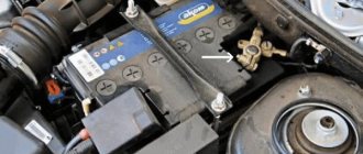
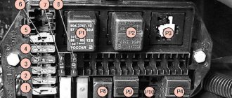
The main cause of a malfunction of the comfort unit is the failure of the control unit relay
. This type of repair involves re-soldering it to a new one.
The most likely cause of a breakdown of the comfort unit is a problem with the relay. Often such blocks cost a lot, and used ones cannot guarantee a long service life. In addition, there are many problems with linking other blocks. There are many examples of failure of comfort units, for example, doors cannot be opened due to a broken relay. To repair the comfort control unit
, it is necessary to determine which relay has broken down.
There are several options:
- The most economical and lightweight.
Having resorted to the help of an electrician, we call the wiring and thus determine which contact of the comfort unit connector is where the breakdown is located. Next, you need to put the tester on the continuity test, touching the contact with one probe, and the connector of the block with the second, we determine which relay it will fit to. - More labor intensive.
It is necessary to take the block, disassemble it and unsolder the relays one by one, thus checking exactly where the bad contact is located. Next, you need to check the resistance at the relay contacts in the operating state and in the off state. The contacts must have no resistance. If even slight resistance is detected at the contacts, this indicates burnt contacts and that voltage is dropping across them.
Thus, it was possible to identify the relay, then all that remains is to replace it.
Basket
Double-glazed window control unit “Norma” 1118 – 6512010 for VAZ 11183 “Kalina”
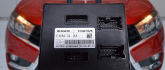
©Aktuator On cars of the Kalina family, 2 types of non-interchangeable (by wiring) glass control controller 1118 - 6512010 and 11180 - 3763040 can be installed. 1118 – 6512010 has one 25-pin connection connector, 1118 – 3763040 (1118 – 3763040 – 10) – two connectors.
Remote control system for double-glazed windows “norm” on a VAZ 11183, Kalina. Controls power windows and central door locking. When the connector is removed, the engine does not start; the device performs some of the anti-theft functions.
Connection
| № | Wire color | Purpose, addressing |
| 1 |
* A regular shock sensor from any alarm system (Alligator, Saturn, Clifford, APS) is suitable.
+ 12 V connect to pin 12; body – on the 6th; We connect the signal wire (a ground appears on it at the moment of activity) to the 1st contact.
During normal arming, Kalina now reacts to an impact on the body (it sounds a horn and blinks turn signals). Similarly, instead of a shock sensor, you can connect a volume sensor (for example, single-level MMS‑1).
You can also connect a pager: + 12 V of the pager transmitter on pin 12, minus on pin 21.
Double-glazed window control unit 1118 – 3763040 (- 10 ) for VAZ 11183 “Kalina”
| External shock or volume sensor input (Not used)* | ||
| 2 | Pink/Black | To the door lock switch in the switch block |
| 3 | Brown/Green | K-Line. To Kl. 71 ECM, Cl. 18 APS‑6 |
| 4 | Brown | Connects to ground when the driver's door is closed |
| 5 | Grey | To rear window heating element |
| 6 | Black | Weight |
| 7 | Pink/White | To the door lock switch in the switch block |
| 8 | Yellow/Blue | In the instrument cluster, to the APS-6 indicator |
| 9 | Black/White | Connects to ground when opening the hood. C VK engine compartment lamp |
| 10 | Two White/Red | Connects to ground when opening the rear doors |
| 11 | Brown/Red | Connects to ground when opening the right front door |
| 12 | Output 12 V power supply for external sensor (Not used)* | |
| 13 | Not used | |
| 14 | Yellow | Pulse + 12 V, closing all doors and trunk |
| 15 | Red/Blue | To class 14 APS‑6 |
| 16 | Blue with Black | To the left direction indicator |
| 17 | Red/Blue | Impulse + 12 V, opening passenger doors |
| 18 | Red/Black | Pulse + 12 V, driver's door opening |
| 19 | Pink/Red | Impulse + 12 V, opening the trunk lock |
| 20 | Yellow/Blue | To terminal “15”, through fuse F 9, in the mounting block |
| 21 | Grey/Black | "-" Horn relay |
| 22 | White/Blue | Connects to ground when the driver's door is opened |
| 23 | Red | To permanent plus through fuse F 5, in the mounting block |
| 24 | Blue | To the right turn signal |
| 25 | White black | Connects to ground when opening the trunk |
| Controller board | ||
| Controller board |
Sign
| Possible reasons | Elimination method |
| The key code is not readable |
1 . 1 Malfunction in the VZ communication coil circuit
1 . 2 Malfunction in the circuit from the block to the communication coil to the APS ECU
1 . 3 Transponder missing in OK
1 . 4 The transponder in OK is faulty (detected during pre-production preparation)
1 . 5 The transponder in the Republic of Kazakhstan is faulty (detected during pre-production preparation)
1 . 6 Malfunction of the input transponder circuit in the APS ECU
1 . 8 The communication coil came off from the VZ pad on the inside
Abbreviations: IS – status indicator; VZ – ignition switch; OK – training key; RK – working key; RC – remote control; KSUD – engine control system controller; ECU - electronic control unit
The Kalina electrical package control unit is used to automatically raise and lower windows and control doors. Additionally, it makes it possible to control alarm activation and trunk opening.
If we are talking about the luxury configuration of Kalina 2, then the electrical package control unit is responsible for blocking the ignition switch. That is why any malfunctions in its operation negatively affect the driving performance of the vehicle.
Advantages of cars with a comfort unit
The standard list of comfort systems on new versions of cars includes:
- interior lighting;
- remote opening and closing of locks;
- window regulators;
- signaling;
- anti-theft systems;
- mirror adjustment;
- heating of the rear machine.
Premium class cars are also equipped with other latest electronics developments that make it possible to create comfort in the cabin.
The driver can recode the settings to suit his own menu.
CBKE schemes
_x000D_
_x000D_
Electrical connection diagram for TsBKE on LADA VESTA: 2 – rechargeable battery; 3 – starter; 4 – rear left outer lamp; 5 – left headlight; 7 – rear window heating relay (K3); 8 – right headlight; 10 – rear outer right lamp; 13 – trunk light; 15 – fuse 60 A (F70); 16 – additional relay (K8); 17 – ignition switch; 26 – alarm switch; 30 – fuse 5 A (F20); 32 – left steering column switch (light alarm switch); 34 – fuse 60 A (F75); 35 – rear window heater; 44 – windshield heating relay 1 (K21); 46 – windshield heater; 47 – lampshade lighting of the glove box; 48 – switch for the glove compartment lamp; 51 – TsBKE (VSM controller); 58 – fuse 30 A (F61); 59 – left threshold lamp (installed on luxury equipment); 60 – right threshold lighting lamp (installed on the “luxury” configuration); 61 – relay of additional consumers (K2); 63 – fuse 10 A (F32); 84 – fuse 3 A (F43); 87 – left outside mirror; 88 – right outside mirror; 120 – additional starter relay (K23); 134 – brake signal switch; 138 – fuse 5 A (F15); 164 – air conditioner control panel (connection diagram for the “comfort” package); 185 – interior lighting unit with ERA-GLONASS interface module; 196 – fuse 5 A (F24); 200 – fuse 15 A (F11); 201 – fuse 15 A (F12); 202 – fuse 10 A (F13); 203 – fuse 10 A (F14); 204 – fuse 5 A (F17); 205 – fuse 5 A (F16); 229 – fuse 3 A (F49); 230 – clutch pedal position signal switch; 231 – windshield heating relay 2 (K22); 233 – fuse 5 A (F80)
_x000D_
- _x000D_
- location of fuses F1-F59 and relays K1-K20 in the interior mounting block;
_x000D_
location of fuses F60-F80 and relays K21-K28 in the motor mounting block
_x000D_
_x000D_
_x000D_
Electrical connection diagram of the TsBKE on LADA VESTA (Comfort package): 2 – rechargeable battery; 3 – starter; 9 – rear inner left lamp; 15 – fuse 60 A (F70); 16 – additional relay (K8); 17 – ignition switch; 20 – fuse 15 A (F1); 23 – rear inner right lamp; 28 – fuse 5 A (F74); 31 – reverse light switch; 33 – right steering column switch (windshield wiper switch); 51 – TsBKE (VSM controller); 63 – fuse 10 A (F32); 79 – electric motor for windshield wiper; 80 – washer motor; 120 – additional starter relay (K23); 198 – fuse 25 A (F40);
_x000D_
- _x000D_
- location of fuses F1-F59 and relays K1-K20 in the interior mounting block;
_x000D_
location of fuses F60-F80 and relays K21-K28 in the motor mounting block
_x000D_
_x000D_
After replacing the TsBKE, it is necessary to perform the training procedure (entering parameters) and automatic configuration of the TsBKE using the Grade-X diagnostic device. You can also view error (fault) codes using this device. You can get acquainted with the functionality of the CBKE in more detail, as well as its diagnostics, using the TI (device, fault diagnosis of the CBKE).
_x000D_
On the one hand, this functional device allows you to more finely tune the operation of the electronics. On the other hand, the unit has a complex structure, which makes independent repairs more problematic. If the TsBKE fails, you will have to contact the dealer, because It is unlikely that the necessary equipment for programming or diagnostics will be at hand.
_x000D_
Attention! It is impossible to retrain a CBKE taken from another vehicle. _x000D_
_x000D_
Which implementation do you like best? The presence of a simple circuit, where there are turn relays, ESP, etc., or the presence of a central electronics control unit? Find other materials on repair, maintenance, modifications and tuning of these cars in the contents (XRAY crossover, Lada Vesta sedan).
Categories of products that may be of interest to you based on the article “Central unit of body electronics Lada Vesta and XRAY (description, reviews)”:
Conversion of the comfort block
To recode the comfort unit, you need to connect the VAG-COM diagnostic adapter to the car and computer. To connect it to the vehicle's comfort unit, you need to turn the key, check the coding code for the comfort unit used on your vehicle and write it down, as it may still be required.
Go to the official Vag-Com website, enter the code of your comfort unit in the “Encoding” field and click the “Decrypt” option. A complete breakdown of the unit’s functions will appear on the monitor. Active functions are marked with a green light and a check mark. If you don’t need some functions, make them inactive, and enable the inactive ones that you need.
Check if everything is connected and activate. To activate the selected options, enter the new code in VAG-COM. If you mess up, you'll have to reset the new settings, enter the old code and start all over again.
Location, purpose and device
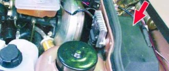
The speed controller in the Lada Kalina car is a device made in a plastic case in the form of a cylinder. Inside the body there is a sensitive component that determines the speed of movement. As you can understand, the main purpose of the device is to accurately determine the speed limit.
As for where the sensor is located, it is located on the car's gearbox, on top. To access it, you need to open the hood - in the engine compartment, an air hose connects the throttle to the air filter. If you remove this pipe, you will be able to see the controller directly below it, on the top of the transmission.
Comfort block problems and their elimination
The most common cause of malfunctioning lighting, opening and closing windows and doors, locks and other elements are rusted or burnt (sticking) contacts of the comfort unit relay. They usually deteriorate due to moisture getting on the wires and the comfort unit.
If a faulty device is left in place or removed, the comfort functions will no longer function. Many car owners, due to the high price and complexity of connecting new blocks, tend to buy a used block or try to repair an old one.
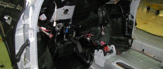
The repair involves re-soldering, since the comfort block is a circuit, and if it doesn’t work, it means something has fallen off, burned or become corroded. Before starting repairs, you need to find out which relay is broken. In most cars, the comfort unit is located under the driver's seat.
The ECU on Kalina is filled with antifreeze - what to do?
After the block filled with antifreeze has been removed, its initial inspection should be carried out. For these purposes, it is necessary to remove 4 screws using a star screwdriver. Then you should slowly remove the control board for a visual inspection. The most common failure is the burnout of the ignition coil output switch. In this case, repair will not help.
As a result of such a malfunction, the Lada Kalina starts working on only 2 cylinders, and sometimes refuses to start at all. You can cope with a similar problem in a stationary workshop. There they will remove the damaged element, wash and dry it. The second most common problem is board burnout. It is not difficult to detect such a defect: the characteristic blackening of the board will leave no doubt.
Is it possible to repair the ECU in this case? The answer to this question can only be given by a service center, but experience shows that repairs will not help here. A complete replacement is required. It happens that sometimes the brain circuitry is slightly damaged. If this happens, then the car owner can get off easy. To restore the car to working order, you will need some minor repairs:
- wipe the block with a dry cloth;
- rinse with WD-40 several times and blow it out with a compressor;
- rinse several times in alcohol and blow again with a compressor;
- dry well, otherwise the Lada Kalina will not move;
- drying takes at least 1-2 hours.
Replacing the relay on the comfort unit
The sequence for replacing the relay on the comfort unit:
- Open the back cover of the unit; to do this, press the connector contacts to pull out the board.
- Call the contact and after detecting a breakdown, proceed to replacing the relay.
- Using a utility knife, remove the anti-corrosion varnish from the contacts of the relay that is to be replaced.
- Lubricate the contacts with flux and solder them with a soldering iron.
- Remove all tin using a special tin sucker to free the burnt relay from the board.
- Remove the faulty relay, insert a new one and solder it carefully.
- Remove any remaining flux with a cloth soaked in alcohol.
- Reassemble the comfort block in reverse order.
- Install it in your car.
If the comfort unit has been replaced, the keys need to be “trained” so that they recognize the car. This procedure is usually performed using VCDS.
Video “Independent repair of the control module”
How to properly dismantle the CBKE and how to subsequently repair it - detailed instructions describing all the nuances are presented in the video below (author - MultiAlexander9).
After restyling, instead of fuses and numerous relays, the Lada Kalina is equipped with a central body electronics control unit (CBEC). The device is available in “Lux” and “Norma” trim levels.
Let's sum it up
If symptoms appear, the owner of LADA Kalina should contact service as soon as possible, because the cost of repairs can be significantly reduced. It is advisable to independently carry out the procedures we have indicated if the owner of LADA Kalina has a sufficient level of experience in dealing with automotive electronic devices. To do this, at a minimum, you need to know where the ECU is located, as well as how to remove the ECU. However, a 100% positive outcome of the event should not be expected. In case of failure, we recommend contacting the service specialists.
Installing the controller
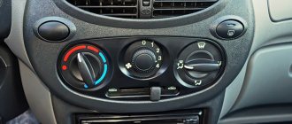
1) For the LADA PRIORA family, attach the bracket to the controller and secure it with screws. Screw tightening torque 1.2…1.6 Nm (Phillips screwdriver, Phillips head, torque screwdriver). Install the controller on the car and secure it with nuts. The tightening torque of the nuts is 1.9…4.5 Nm (spanner 8, interchangeable head “8”, torque wrench).
For the LADA KALINA family, attach the bracket to the controller and secure it with screws. Screw tightening torque 1.2…1.6 Nm (Phillips screwdriver, Phillips head, torque screwdriver). Install the controller on the car and secure it with a screw. The tightening torque of the screw is 1.7…3.5 Nm (Phillips screwdriver, Phillips head, torque screwdriver).
For the LADA 4x4 family, install the controller on the car and secure it with nuts. The tightening torque of the nuts is 1.9…4.5 Nm (spanner “8”, interchangeable head “8”, torque wrench).
2) Connect the wiring harness connectors to the controller.
3) Install the instrument panel console screen into place (using a Phillips screwdriver). For the LADA 4x4 family, install the left front upholstery.
4) Connect the wire to the negative terminal of the battery (spanner “10”).
Removing the controller
To quickly remove the electronic control unit, follow these steps:
Location of the controller in the interior of cars of the LADA 4x4 family
- Turn off the ignition.
- Disconnect the wire from the negative terminal of the battery (spanner “10”).
- Unscrew the fastening screws and remove the right screen of the instrument panel console (using a Phillips screwdriver). For the LADA 4x4 family, remove the left front upholstery.
- Disconnect the wiring harness connectors from the controller.
- For the LADA PRIORA family, unscrew the two nuts securing the controller and remove the controller assembly with bracket from the car (wrench “8”). Unscrew the four screws and disconnect the bracket from the controller (using a Phillips screwdriver).
For the LADA KALINA family, unscrew the screw securing the controller and remove the controller assembly with bracket from the car (a Phillips screwdriver). Unscrew the four screws and disconnect the bracket from the controller (using a Phillips screwdriver).
New Lada: DIY connection diagram for fog lights on Kalina • Auto electrician himself
For the LADA 4x4 family, unscrew the four nuts and remove the controller (wrench “8”).
If the controller malfunctions, a “clean” controller must be used for replacement.