A normal level of pressure ensures vehicle controllability, long-term tire operation, economical fuel consumption and driving safety. Automatic pressure control systems began to be developed in the 70s of the twentieth century and were initially installed on military trucks along with an automatic inflation system:
- in 1987-1989 - the first automatic control system was installed on the Porsche 959 model;
- since 1991 - for all Chevrolet Corvette cars;
- since 2008 - the option has become mandatory for all cars produced in the USA and then in a number of EU countries.
The pressure sensor is the main part of the automatic system.
In Russia you can select the systems and pressure sensors you need. If you are interested in purchasing new tires and wheels, then you can safely contact the online store https://www.planetakoles.ru/.
Working principle of the tire pressure sensor
Today, most modern cars in the mid-price segment are equipped with a special pressure sensor. This implies the ability to constantly monitor the amount of air in the tires.
To designate the system in question, the abbreviation TPMS is used - Tires Pressure Monitoring System. The system, built into the vehicle from the factory, automatically alerts you when the pressure is too low. The system in question can be purchased and subsequently installed separately. In the USA, EU and some Asian countries, the installation of TPMS is mandatory for all vehicles without exception.
All sensors that allow you to control air pressure levels can be divided into two main categories:
- indirect;
- direct
The operating principle of these is different.
Tire replacement / maintenance / TPMS service
- When replacing tires for TPMS systems, the following must be observed:
- Check the sensors for functionality and carry out maintenance if necessary. Valve repair.
- Every time you change a tire, you should check the TPMS batteries and replace them if necessary. Switch.
- Direct TPMS systems require special software that must be adapted to the vehicle, sensor manufacturers provide this. Each built-in sensor has its own ID, this ID must be learned from the vehicle in order for the vehicle to correctly recognize which wheel is losing air.
- TPMS systems require specialized knowledge and absolutely require a tire dealer to change the tires.
- If your vehicle doesn't already have a TPMS, it doesn't need to be upgraded. New vehicles must only be equipped with a TPMS system from November 2014 onwards.
Indirect pressure measurement system
This design is the most simply constructed. Therefore, its cost is relatively low. In fact, it is an extension of the ABS software block. In fact, the system does not register a lack of pressure, but a decrease in wheel dimensions.
If there is a puncture, air and tire escape, its diameter decreases. The relevant information is transmitted to the ECU, after which it is compared with the specified standard parameters. Detection of discrepancies allows you to determine which wheel has a puncture. Then the signal about insufficient pressure “lights up”.
Another variation is to measure the wheel speed. This solution is also a subroutine built into the ABS system. The length of the path for each bus is determined. Next, the information received is checked and compared with that recorded in the ABS. A discrepancy is indicated by an appropriate signal.
Since the determination of the proper pressure level is determined on the basis of the data obtained and their comparison, calibration is required after service work. The ECU receives new data for subsequent comparison with information received from the ABS subsystem. The main advantages of the indirect system:
- relatively low price;
- lack of additional structural elements.
There is also a significant drawback: low accuracy. The threshold for deviation from the specified pressure is 30%.
Direct pressure measurement system
This scheme involves receiving data from each wheel through a special sensor. The work scheme assumes the presence of:
- tire pressure sensor;
- Control block;
- display;
- special antenna.
Installing pressure sensors usually does not cause any difficulties. This device is a regular valve; it is inserted into the wheel instead of the standard one. Information is transmitted to the central control node via a wireless channel. A certain frequency is established. Typically the interval is 1 minute.
It should be noted that the battery needs to be replaced periodically. Typically, the service life of one battery is 7-10 years. The battery itself is most often a compact battery in the form of a small tablet.
An important component is the receiving antenna. It receives information from all sensors simultaneously and transmits them to the control unit. Typically, the central locking antenna acts as a receiving antenna.
On expensive cars or in the maximum configurations of mid-level vehicles, an individual antenna is used for each sensor. Such a receiver is usually located in the wheel arch of the vehicle. An important advantage of this design is the ability to control the pressure in all wheels individually. Resetting an error usually does not require special equipment.
The main computing device in such systems is the control unit. It receives information from all sensors without exception. Then it analyzes them: compares the obtained values with the standard ones. If there is a discrepancy, it displays a message on the vehicle’s instrument panel. It is worth noting: not all systems allow monitoring tire pressure on each wheel.
You will need to stop the car, check the level in all wheels, and then fix the problem. Some systems allow you to display text and graphic information on a special display. This greatly simplifies wheel diagnostics and makes it more accessible.
Some TPMS allow you to evaluate the level of pressure change and determine its intensity:
- minor;
- strong;
- sudden.
Certain types of TPMS provide for automatic adaptation: no manipulation of the system is required. In some cases, when replacing tires or sensors, reprogramming is required using special equipment. You can also enter the required values yourself. But this is not possible on all TPMS models.
Vehicle Tire Pressure Monitoring System (TPMS) Protocol Study
Tire Pressure Remote Monitoring System (TPMS )
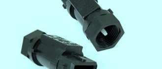
— Tire Pressure Monitoring System) is designed to promptly inform the user about a decrease in tire pressure and the critical temperature of the tires. Sensors are available in internal or external versions. The internal ones are installed inside the tire of a tubeless wheel, the external ones are screwed onto the wheel fitting. A wheel with an internal sensor is completely identical in appearance to a wheel without a sensor. Such a wheel is easy to inflate. The external sensor is noticeable, it can be stolen, and when inflating the wheel, it must first be unscrewed. It is also exposed to atmospheric phenomena.
I was prompted to study the operating protocol of the TPMS system by the idea of installing such a system on a baby stroller for operational monitoring of tire pressure.
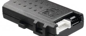
Fig.1. Appearance of the TPMS system
Fig.2.
TPMS system controller board It was not possible to simply install a standard receiving unit, since its minimum permissible pressure value is 1.1 Bar, and in a stroller it is less. Therefore, the module constantly beeps, informing about low tire pressure. You can read about the development of a controller for the “Smart” baby stroller “Maximka”, in which the research results were applied, in my article [1].
I started collecting information about the work of TPMS by searching for articles on the Internet. But, unfortunately, there is little information. Yes, and it usually concerns standard car systems, which are a little more complicated and much more expensive. But I needed information about a simple Chinese cheap system. I had some minimal understanding, now I had to start experimenting.
So, we arm ourselves with the USB whistle of the DVB tuner, launch RTL-SDR and watch the broadcast. The sensors operate at a frequency of 433.92 MHz in FSK modulation. Initially, I recorded the broadcast and then manually parsed the protocol. This is where the difficulties began. Previously I only encountered OOK modulation. Everything is simple there. It's a little more complicated here. Information is encoded at two frequencies. Therefore, I studied examples and theory on modulations. Then I saw how the URH-Universal Radio Hacker program was used [2, 3]. I tried to install it, but it doesn’t work on my WinXP 32bit. I had to look for a computer with win8 64bit and then the program was installed. You can read more about its work on the developer’s website. URH made the process easier for me in some ways, because... it captures a signal from the air, displays it as an oscillogram and immediately decodes it into raw digital form in both binary and hex form.
Fig.3. Screenshot of a program with a captured frame of a TPMS message
The sensor sends several parcels one after another in one session. The period between sessions can reach a minute or even more. If an alarming situation occurs, the sensor immediately begins sending data packets. Sound file of the message from the sensor [8]. An example of one message from a sensor taken from the URH program:
010101010101010101010101010101010101010101010101010101010101010101010101010101010101010101010101010101010101010101010101010 1010101010101010101010101010101010101010101010101010101010101010101010101010101010101010101010101010101010101010101010101010101 01010101010101010101010101010110011001101001101010010110010110100110101001101010011001010101010110100101010101010101101010010 11001101010010101100101101001010101011001011001100110101001 In hexadecimal form, this premise will take the form: 5555555555555555555555555555555555555555555555555555 5555555555555556669a965a6a6a6555a5555a966a565a556599a9 It was clear that all 4 parcels in one session had the same data, which means the packet was received correctly and we can begin to analyze it.
In the example above you can see the preamble (sequence 01010101....), then comes the data. After reading the Internet, we understand that this is a parcel encoded with Manchester encoding (GE Thomas). Each bit is encoded by two bits 01 or 10. I initially encoded by hand, thereby reinforcing the encoding/decoding theory. But then I decided to turn to an online decoder [4,5,6], which greatly speeded up the process.
So, having decoded the original message from the sensor using the Manchester code, we get
000000000000000000000000000000000000000000000000000000000000000000000000000000000000000000000000000000000000000000000000000000000000000000000000000000000000000000000000000000000000 000000000000000010101101110010011011101110100000011000000001110010111000100110000010010101110 The first 136 zeros are a preamble, it can be discarded. We are only interested in data.
Converting them to hexadecimal form, we get: 0x15B937740C03971304AE
This already has beautiful initial data, which somewhere contains an identifier, tire pressure and temperature.
For further research it is necessary to collect data statistics. To do this, I screwed one sensor to the wheel and captured the air, while simultaneously recording what the original system display showed. I released the pressure, pumped it up, put the wheel in the freezer for a negative temperature, and heated it up. Then I achieved the same conditions for another sensor to find out the temperature and pressure bytes.
The entire package takes 10 bytes. If you arrange the received decoded data in a column, you can see constant data and changing data.
15B937740C03971304AE 15B937740C03A1FC00A4 15B937740C03A700087B The sensors have stickers on the housing. Each sensor has a different one: 0A, 1B, 2C, 3D.
Stereotypical thinking did not help here. I thought that this was the ID sensor. I doubted why the ID took up only 1 byte, but then I forgot about it and tried to look for these identifiers in the stream. Then in the menu of the original system receiver I saw that other sensors can be linked to this receiver, and the receiver itself shows the sensor identifier on each wheel. And, lo and behold, I discovered that the fourth wheel sensor has ID = 3774.
15B937740C03971304AE This means that the 3rd and 4th bytes of the parcel are the wheel identifier. I compared it with other sensors and the identifiers also coincided with those displayed by the standard panel.
I counted the 1st byte as the prefix of the beginning of the data, and the 2nd byte as the identifier of the TPMS subsystem. Below I have provided parcels from different sensors for comparison.
15B9F3FA2300BE1B007B Sensor 0A ID=0xF3FA 15B91AA43201B71B002A Sensor 1B ID=0x1AA4 15B9ABFF32027B1B029B Sensor 2C ID=0xABFF 15B937740C03971304AE Sensor 3D ID =0x3774
And I realized that the inscriptions on the sensors (0A, 1B, 2C, 3D) are just wheel numbering in digital and alphabetic form, and not a hexadecimal wheel identifier. But, nevertheless, the 6th byte in the parcel is very similar to the serial number of the sensor. I concluded for myself that this is the wheel identifier. This means that one more byte has been decoded.
The last byte is most likely a checksum, which I don’t know how to calculate yet. This remained a mystery to me until the very end.
The next byte decoded is the wheel temperature. Lucky here. The temperature takes 1 byte and is presented in whole degrees. Negative temperature in additional code. This means that a temperature of -127…128 degrees Celsius will fit into a byte.
In our package, temperature is the 8th byte
15B9F3FA2300BE1B007B 0x1B corresponds to +27 degrees 15B937740C03A1FC00A4 0xFC corresponds to -4 degrees
There are three unrecognized bytes left: 5th, 7th, 9th. Judging by the dynamics of changes in tire pressure, the tire pressure is hidden in 7 bytes, and in the 9th byte, most likely, the status bits of the sensor. According to various sources of information on the Internet, as well as the functionality of my TPMS system, there should be a low battery bit, a rapid pressure loss bit, and a couple more bits that are not clear for what.
So, we will analyze the 7th byte, because we mean that the pressure is hidden in it. Having collected statistics on different sensors with different pressures, I could not clearly determine the formula that recalculates the pressure. And it is not clear in what default units the sensor transmits pressure (Bar, PSI). As a result, the table built in Excel did not provide an exact match with the standard TPMS display. One could neglect this difference of 0.1 Bar, but I wanted the concept of a protocol down to the last bit. The excitement took over.
If you can’t understand how the pressure byte is generated, then you need to make an emulator of the pressure sensor and, changing the pressure value, see what the standard panel displays.
It remains to find out the purpose of the 5th and 9th bytes of the packet, but they rarely change, so you can take their values as in the original packet, changing only the pressure byte. Now the only question is calculating the checksum. Without it, the standard panel will ignore my package and show nothing.
To emulate the sensor, it was necessary to transmit a packet. To do this, I had an SI4432 transceiver connected to a PIC16F88, once used for other purposes.
Fig.4. Photo of the test board
Taking advantage of old data transfer practices, I sketched out a program for PIC that transmits one of the packets that I received from the URH program. Some time after turning on the transmitter, the panel displayed the data that was transmitted to it! But this is a ready-made package with a ready-made CRC, and in order for me to change the pressure byte, I also need to recalculate the CRC.
I started reading, looking for information about what CRCs are used, tried different Xor, And, etc., but nothing worked. I already thought that nothing would work out and that I would have to be content with the pressure that I received according to my table, but it did not coincide a little with the original scoreboard. But on the Internet I saw an article about the selection of CRC. There was a program to which you give several packets, and it tries to find a checksum and, if successful, produces the value of the polynomial and the CRC initialization value. [7]
We specify several packages for the program:
reveng -w 8 -s 15B9ABFF3202AA1B0017 15B9ABFF3202AA1B0249 15B9F3FA2300D01A00D8 15B937740C037B130089 15B937740C03BD18025E 15B9ABFF32028F150834 The program produces: width=8 poly=0x2f init=0x43 refin=false refout=false xorout=0x00 check=0x0c residue=0x00 name=(none) I wrote a program for calculating CRC taking into account this data and ran it through the packages that I received earlier - everything came together! // I consider the CRC for this crc=0x43; // Initial value for correct calculation for(j=0;j<9;j++) { crc ^= tmp[j]; for(i=0;i<8;i++) crc=crc&0x80 ? (crc<<1)^0x2F : crc<<1; // Polynomial 0x2F to calculate the correct CRC } My hands were itching to broadcast pressure data. Having supplemented the test program with CRC calculations, I transmitted the first packet. The standard panel received the signal and displayed pressure and temperature. A small problem was that the standard panel had one decimal place and, when transmitting the value on the air, the same pressure was always displayed on the screen, because the remaining digits were invisible. Transmitted byte value 0..255. But again it’s somehow not clear. It turned out that the pressure of 0.00 Bar begins when the 7th byte contains the value 97. It is not clear why this is so. But then, with a discreteness of 0.01 Bar, everything is clear.
Byte P Pressure, Bar 255 1.58 254 1.57 … … 107 0.10 106 0.09 105 0.08 104 0.07 103 0.06 102 0.05 101 0.04 100 0.03 99 0, 02 98 0.01 97 0.00
Judging by the table, the maximum pressure that fits in one byte is only 1.58 Bar, but the system allows you to measure pressure up to 4 Atm. This means that 1 bit of the most significant bit is hidden somewhere else. There was no desire to go through all the bytes and change the bits in them. A car wheel was found, a sensor was screwed onto it, and the signal was captured. Curiosity got the better of me and I made mental bets on where this bit would appear. And that it will be exactly one bit, and not some other encoding scheme.
After decoding the packet, I saw this bit. It is the 7th bit of the 6th byte. This means that the 6th byte contains not only the wheel number, but also the most significant bit of the tire pressure. 15B937740C833C18025C
The most significant bit from 0x83 and 0x3C gives 0x13C = 219 which corresponds to a pressure of 2.19 Bar Formula for converting pressure to Bar: P=(ADC-97)/100, Where ADC = (B7>>7)*0x100+B6, where B6 and B7 is the value of byte 6 and byte 7.
With a value of 511 we have a maximum pressure of 4.14 Bar. It was also not clear why the bar is 4.14 Bar, but I guess that this is equal to 4 Atm - the maximum permissible pressure for the sensor.
It remains to understand what the status bits are responsible for. By releasing the pressure, connecting the sensor to a regulated power supply and reducing the voltage, the bits were obtained. 2 bits remained unclear. There may be more, but they never took the value of one during all the experiments.
To simplify the analysis, a program was written [8]
Fig.5. Appearance of the program interface for studying TPMS packages
The program can be given a raw packet from the URH program in hexadecimal form and the program decodes the packet, calculates the checksum and displays the data in normal units of temperature and pressure.
Somehow I went back to the standard panel menu and saw that the sensor identifier was not two bytes, but four. The panel has large and small indicators and I did not immediately notice that the 2nd and 5th bytes are also included in the sensor identifier.
15B937740C833C18025C
Thus, only the 1st byte remains unrecognized, but it is always 0x15 (0b010101), and this looks like some kind of packet preamble or identifier of its beginning.
Also, the status bits are not accurately recognized, but there are enough of those that exist.
Curiosity to find out what was inside the sensor took over and I disassembled one of them (Fig. 6)
Fig.6. TPMS sensor
It is based on an Infineon SP372 chip with a small trim. A search for documentation for this particular microcircuit yielded nothing. The ones I found were either review or advertising. So it was not possible to find out about the protocol. But the articles mention that this is a programmable controller, so the program can be anything. Therefore, I did not risk buying the microcircuit separately.
Protocol
Now about receiving data from the sensor to the SI4432 transceiver.
The original plan was to receive raw data from the SI4432 so that the controller would decode Manchester and collect the bytes. But this transceiver has a packet processing function. That is, for transmission, you can set the transmitter to the desired frequency, modulation, deviation, set the preamble length, encoding, sync word, bit rate, data length. Then write the original data packet into the transmitter buffer (for example, our 15B937740C833C18025C) and start the transmission. The transceiver itself will generate a packet and broadcast it, observing all the specified parameters, and the controller at this time is free to process other information. Ideally, I wanted to get batch processing of data from the SI4432 when receiving. For the receiver to receive the packet and generate an interrupt indicating that the packet has been received. Then the controller simply reads the receive buffer, which already stores data in its pure form, thereby freeing up processor time for other functions.
I began to study setting up registers for the reception transceiver. This turned out to be much more difficult than transmitting the package. Here you need to know well the theory of radio reception, which I don’t have. There are register calculation tables in Excel for this transceiver, but they either do not work due to the fact that Excel is Russian, or they are truncated. There is also an application from the developer, but everything there is also not very transparent. After going through many examples and looking at calculation tables, I manually calculated the register values according to the documentation.
I connected a logger to the receiver output and captured the air, looking at what the receiver outputs. As a result, I managed to configure the receiver filters so that it would let my packet through. He manipulated the speed of the flow, beat the tambourine. The theory, unfortunately, is still not clear to me.
In order for the receiver to receive a data packet, it must indicate the length of the preamble, the sync word, which must be present, and the length of the data. It is also possible for the receiver to calculate the checksum itself, but in the SI4432 the calculation algorithm does not correspond to the CRC algorithm of pressure sensors.
The mandatory presence of a two-byte sync word could have clouded the idea of receiving the packet, but it was lucky that the message from the sensor starts at 0x15B9 (15B937740C833C18025C) and is the same for all sensors. This means that 0x15B9 was set for the sync word. The data packet length is 8 bytes, checksum analysis is disabled. We set the interrupt to be generated when a packet is received and start the reception procedure.
When the receiver receives the preamble, sync word 0x15B9 and 8 bytes of data, it will issue an interrupt to the main controller, which simply reads 8 bytes of data from the receiver buffer. Next, the main controller will calculate the checksum, compare it and decode the received data. Fortunately, everything worked out as planned!
Fig.7. Photo of the standard TPMS indicator and smart stroller display
Below is an example of initializing the SI4432 transceiver for reception:
WriteSI4432(0x06, 0x05); // interrupt all disable WriteSI4432(0x07, 0x01); // to ready mode WriteSI4432(0x09, 0x7f); // cap = 12.5pf WriteSI4432(0x0A, 0x06); // uC CLK: 1 MHz WriteSI4432(0x73, 0x00); // no frequency offset WriteSI4432(0x74, 0x00); // no frequency offset WriteSI4432(0x75, 0x53); // 430-440MHz range WriteSI4432(0x76, 0x62); // 0x621A-433.924 kHz WriteSI4432(0x77, 0x1A); // low part WriteSI4432(0x79, 0x00); // no frequency hopping WriteSI4432(0x7a, 0x00); // no frequency hopping // Configuring receiver registers for speed 9090/2 WriteSI4432(0x1C, 0x81); // 01 IF Filter Bandwidth register WriteSI4432(0x1D, 0x44); // 44 AFC Loop Gearshift Override register WriteSI4432(0x1E, 0x0A); // 0A AFC Timing Control WriteSI4432(0x1F, 0x05); // 00 Clock Recovery Gearshift Override WriteSI4432(0x20, 0x28); // 64 Clock Recovery Oversampling Ratio register WriteSI4432(0x21, 0xA0); // 01 Clock Recovery Offset 2 register WriteSI4432(0x22, 0x18); // 47 Clock Recovery Offset 1 register WriteSI4432(0x23, 0xD2); // AE Clock Recovery Offset 0 register WriteSI4432(0x24, 0x08); // 12 Clock Recovery Timing Loop Gain 1 register WriteSI4432(0x25, 0x19); // 8F Clock Recovery Timing Loop Gain 0 register WriteSI4432(0x2A, 0x00); // 00 AFC Limiter register WriteSI4432(0x69, 0x60); // 60 AGC Override 1 WriteSI4432(0x70, 0x26); // Manchester encoding, data in inversion WriteSI4432(0x71, 0x22); // FSK modulation, FIFO WriteSI4432(0x72, 31); // Deviation 31*625=19375 Hz (you can try to remove it in receive mode) WriteSI4432(0x34,10); // 10 — preamble length in 4-bit nibbles WriteSI4432(0x35.0x1A); // preambula threshold WriteSI4432(0x36,0x15); // Sync word 3 is 0x15 WriteSI4432(0x37.0xB9); // Sync word 2 is 0xB9 WriteSI4432(0x27.0x2C); // RSSI // Header settings WriteSI4432(0x33, 0x0A); // fixpklen=1, Synchronization Word 3 and 2 WriteSI4432(0x32, 0x00); // Disable header filtering WriteSI4432(0x30, 0x80); // Skip2ph, Enable Packet RX Handling=0 (you can try removing Skip2ph...) WriteSI4432(0x3E, 0x08); // Received data length is 8 bytes WriteSI4432(0x0B, 0x12); // setting GPIO0 to enable TX transfer mode WriteSI4432(0x0C, 0x15); // configure GPIO1 to enable RX receive mode // Reset FIFO TX WriteSI4432(0x08, 0x01);//write 0x01 to Operating Function Control 2 register WriteSI4432(0x08, 0x00);//write 0x00 to Operating Function Control 2 register // Reset FIFO RX WriteSI4432(0x08, 0x02);//write 0x02 to Operating Function Control 2 register WriteSI4432(0x08, 0x00);//write 0x00 to Operating Function Control 2 register //Disable all interrupts except: Receive preamble, Receive sync word, Receive packet WriteSI4432(0x05, 0x02); // Interrupt when receiving a packet WriteSI4432(0x06, 0x00); //Reading interrupt status registers to clear current interrupts and reset NIRQ to log. 1 SI4432_stat[0] = ReadSI4432(0x03); SI4432_stat[1] = ReadSI4432(0x04); WriteSI4432(0x07, 0x05); // Turn on RECEIVING the air The data reception itself will look like this: if (si_int) // If an interrupt has arrived from the receiver SI4432 { //reading status registers to clear interrupt flags SI4432_stat[0] = ReadSI4432(0x03); SI4432_stat[1] = ReadSI4432(0x04); SI4432_RSSI = ReadSI4432(0x26); if (SI4432_stat[0]&0x02) { WriteSI4432(0x07, 0x01); // I complete the reception. Thus, you can continue later. If you do not complete, then the packets will no longer be accepted SI4432_ReadFIFO(); // Read 8 received bytes from the FIFO TPMS_Parsing(); // Check CRC and parse data // Reset FIFO WriteSI4432(0x08, 0x02); // write 0x02 to Operating Function Control 2 register WriteSI4432(0x08, 0x00); // write 0x00 to Operating Function Control register 2 //WriteSI4432(0x07, 0x05); // Enable RECEIVING ether } else { // Reset FIFO TX WriteSI4432(0x08, 0x01);//write 0x01 to Operating Function Control 2 register WriteSI4432(0x08, 0x00);//write 0x00 to Operating Function Control 2 register // Reset FIFO RX WriteSI4432(0x08, 0x02);//write 0x02 to Operating Function Control register 2 WriteSI4432(0x08, 0x00);//write 0x00 to Operating Function Control register 2 } if (SI4432_stat[0]&0x80) { // Reset FIFO RX WriteSI4432(0x08, 0x02);//write 0x02 to Operating Function Control 2 register WriteSI4432(0x08, 0x00);//write 0x00 to Operating Function Control 2 register } WriteSI4432(0x07, 0x05); // Enable RECEIVING ether si_int=0; } The SI4432_ReadFIFO() function simply reads 8 bytes from the receiver buffer, which contain the data from the sensor.
The TPMS_Parsing() function parses the checksum and decodes the information into final units of pressure and temperature, as well as status information.
Problems
- While reading information about sensors, synchronization of sensors with each other was mentioned. For some reason it is necessary to pair the sensors, there was something about a speed of more than 20 km/h for 30 minutes. It is not clear why this is necessary. This may be due to the timing of the information transfer, but this is my guess.
- I haven’t fully figured out the functions of the pressure sensor status bits.
- It is not clear about setting up the SI4432 transceiver for reception, or about the transmission speed using Manchester encoding. It works for me, but I don’t understand the principle yet.
Results of work
The research covered in this article took about a month of free time.
As a result of the work on studying the protocol for the operation of the tire pressure monitoring system, issues of transmitting and receiving data over the air were raised, signal encoding was briefly considered, and the SI4432 transceiver was tested for transmission and reception. This task made it possible to integrate TPMS into the main project of a “smart” stroller. Knowing the exchange protocol, you can connect more sensors and integrate them into your development. Moreover, the controlled pressure can be within a wide range, and not as in the standard system 1.1-3.2 Bar, because pressure outside this range is accompanied by an alarming squeak from the system of the standard central unit. TPMS can also now be used to monitor tire pressure on a motorcycle, bicycle or, for example, an air mattress. All that remains is to physically install the sensor and write a top-level program.
Links
- “Smart” baby stroller “Maximka”
- github.com/jopohl/urh
- www.rapidtables.com/convert/number/hex-to-binary.html
- www.rapidtables.com/convert/number/binary-to-hex.html
- eleif.net/manchester.html
- hackaday.com/2019/06/27/reverse-engineering-cyclic-redundancy-codes
- My utilities, sample package, CRC selection. Archive password "tPmSutiLity" dropmefiles.com/MtS9W"
- i56578-swl.blogspot.com/2017/08/eavesdropping-wheels-close-look-at-tpms.html
- www.rtl-sdr.com/tag/tpms
Where are the pressure sensors and their main types?
It won’t be difficult to figure out how the pressure sensor works on your own. All of them can be divided into the following main categories:
- mechanical type;
- electric.
Mechanical ones are a structure that transmits data in analog form to a special control unit. After which it is converted into a form convenient for perception. The operating principle of such devices is relatively simple. This is the main reason for reliability. Such devices function in the same way as conventional pressure gauges.
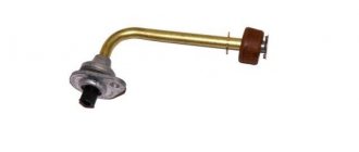
Visually, mechanical sensors look like a regular camera cap - a decorative type. The upper part is transparent, underneath there are 3 coaxial cylinders. They are layers of plastic of different colors. The smallest diameter cylinder is yellow. It is located inside the red one. Under pressure, all layers easily move within each other.
Each color represents pressure. If it is normal, then the color under the cap is green. If it’s a little less than normal, the yellow layer comes out. When it drops below 1.5 atm, the red color is squeezed out.
Electronic sensors are usually installed inside the wheel. The most convenient and accurate is a valve. Installation is expected instead of the standard one installed in the bus. It won’t be difficult to figure out where the sensors are located. Is it easy to figure it out if necessary? how to turn off the system.
Possible faults
Despite the fact that the TPMS is located inside the wheel and is well protected from mechanical damage, its failure can be caused by centrifugal forces, temperature changes and other negative influences. The exact cause of the sensor's malfunction can only be determined through special research, so if you do your own repairs, it is enough to simply replace this part.
The Kia Sportage 4 wheel pressure sensor transmits information to the receiving device via radio frequency, so its performance may be affected by other devices that use a similar principle of data transmission. If the TPMS is malfunctioning due to interference, the warning light on the instrument panel will illuminate yellow. If everything is in order with the wheels and the pressure is at a safe level, then you can turn off the malfunction warning system if the source of the interference is not found.
How to install a pressure sensor in the wheels of a car?
The complexity of self-installation depends on the type of system chosen. For example, conventional mechanical sensors that do not require data transmission to a central control unit do not require special equipment or wheel disassembly. It is enough to install caps with built-in “pressure gauges”.
Electronic sensors in the form of a valve are the most popular. Typically the installation process includes the following main steps:
- the wheel is flanged - instead of standard valves, electronic sensors are installed:
- Next, the sensors are encoded and configured:
- A special receiver is installed in the cabin - to which all data on tire pressure is transmitted:
Sometimes it becomes necessary to install new sensors in place of old ones. The first step is to determine where the system components are located on the vehicle itself. It is necessary to familiarize yourself in advance with all the subtleties and nuances of installation. If you don’t have the necessary experience, you should turn to professionals for help. Especially if the car was purchased new and it is still under warranty.
Using an air pressure control system allows you to avoid serious troubles on the road. Often, the driver simply does not notice that the tire has been punctured and continues to drive on a flat tire. The consequence of this could be a flat tire. Which will lead to skidding and an accident.
The tire pressure sensor allows continuous monitoring of the wheels. It is only necessary to promptly replace the batteries.
Working principle of TPMS
Direct TPMS sensors are a more complex system than indirect monitoring using ABS sensors. In a standard TPMS system, each pressure sensor is combined with temperature, acceleration and voltage sensors. The voltage sensor monitors the condition of the battery, the speed sensor directly activates the pressure sensor itself when the car starts moving, the temperature sensor monitors tire overheating and provides temperature compensation for the transmitted data. The measurement data is transmitted by radio signal to the receiver every 60 s; when the tire pressure changes, the transmission frequency increases to 15 s.