01/25/2022 2,353 Electrical
Author: Victor
CAN bus is a device that makes it easier to control a car by exchanging information with other car systems. Data transfer from one vehicle unit to another is carried out through special channels using encryption.
[Hide]
What is CAN bus
The electronic CAN interface in a car is a network of controllers used to combine all control modules into a single system.
This interface is a block with which the following blocks can be connected via wires:
- an anti-theft system equipped with or without an auto-start function;
- machine motor control systems;
- anti-lock unit;
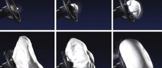
- safety systems, in particular airbags;
- automatic transmission control;
- control panel, etc.
Device and where the bus is located
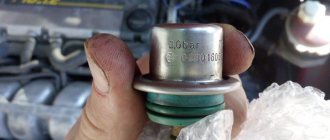
Structurally, the CAN bus is a block made in a plastic case or a connector for connecting cables. The digital interface consists of several conductors called CAN. One cable is used to connect blocks and devices.
The installation location of the device depends on the vehicle model. Usually this nuance is indicated in the service manual. The CAN bus is installed in the vehicle interior, under the control panel, and can sometimes be located in the engine compartment.
How does it work?
The operating principle of the automatic system is to transmit coded messages. Each of them has a special identifier that is unique. For example, “the temperature of the power unit is 100 degrees” or “the vehicle speed is 60 km/h.” When transmitting messages, all electronic modules will receive relevant information, which is verified by identifiers. When data transmitted between devices is related to a specific block, it is processed; if not, it is ignored.
The length of the CAN bus identifier can be 11 or 29 bits.
Each information transmitter simultaneously reads the data transmitted to the interface. The lower priority device must let go of the bus because the high dominant level is distorting its transmission. At the same time, the package with the increased value remains untouched. A transmitter that has lost connection restores it after a certain time.
The interface connected to the alarm or automatic start module can operate in different modes:
- Background, which is called sleeping or standalone. When it is running, all major systems of the machine are disabled. But at the same time, the digital interface receives power from the mains. The voltage is minimal, which prevents battery discharge.
- Startup or wake-up mode. It begins to function when the driver inserts the key into the lock and turns it to activate the ignition. If the machine is equipped with a Start/Stop button, this occurs when it is pressed. The voltage stabilization option is being activated. Power is supplied to controllers and sensors.
- Active. When this mode is activated, the data exchange procedure is carried out between regulators and actuators. The circuit voltage parameter increases because the interface can draw up to 85 mA of current.
- Deactivation or falling asleep. When the powertrain stops, all systems and components connected to the CAN bus stop functioning. They are deactivated from the vehicle's electrical network.
Characteristics
Technical properties of the digital interface:
- the general information transfer speed is about 1 Mb/s;
- when sending data between control units of different systems, this figure decreases to 500 kb/s;
- the information transfer speed in the “Comfort” type interface is always 100 kb/s.
The “Electrical Engineering and Electronics for Programmers” channel talked about the principle of sending packet data, as well as the characteristics of digital adapters.
Working with the terminal
Before operation, you must take into account the recommendations for use, which are indicated in the service manual. The device is pre-configured.
Setting options
If you are using a terminal, there are two options to configure the interface:
- Using a special “Configurator” program for your computer. When starting the utility, go to the “Settings” tab and select the CAN item. In the window that opens, the necessary parameters are indicated.
- Using the "CanRegime" commands. Typically this option is used for remote configuration using SMS messages. Commands that are sent from monitoring software may be used.
More details about the commands that are specified after CanRegime:
- Mode—defines the operating mode. If the number is 0, then the digital interface is disabled, if 1, the standard filter is used. Numbers 2 and 3 indicate that the packets belong to the 29- or 11-bit class.
- BaudRate. The command is intended to determine the speed of the digital interface. It is important that this parameter matches the speed of information transfer in the car.
- TimeOut - Defines the timeout for each message. If the received value is too low, then the digital interface will not be able to catch all transmitted messages.
Types of CAN buses
Conventionally, CAN buses can be divided into two types according to the identifiers used:
- KAN2, 0A. This is how digital devices that can operate in an 11-bit data exchange format are marked. This type of interface, by definition, cannot detect errors on signals from modules operating with 29 bits.
- CH2, 0V. This is how digital interfaces operating in 11-bit format are marked. But the key feature is that error data will be transmitted to the microprocessor devices if a 29-bit identifier is detected.
CAN buses can be divided into three categories according to their type:
- For a car's power unit. If you connect this type of interface to it, this will allow for fast communication between control systems via an additional channel. The purpose of the bus is to synchronize the operation of the engine ECU with other components. For example, gearbox, anti-lock braking system, etc.
- Comfort type devices. This type of digital interface is used to connect all systems in this category. For example, electronic adjustment of mirrors, heated seats, etc.
- Information and command interfaces. They have a similar information transfer speed. They are used to ensure high-quality communication between the nodes necessary to service the vehicle. For example, between an electronic control unit and a navigation system or smartphone.
The “Electrical Engineering and Electronics for Programmers” channel spoke about the principle of operation, as well as about the types of digital interfaces.
Operating modes
There are several operating modes of the terminal:
- FMS - in it the car owner can find out the total fuel consumption, revolutions, vehicle mileage, axle load, and temperature of the power unit. It is possible to obtain data on the volume of fuel in the tank. To work in this mode, enter the filter type selection menu of the Configurator program. Specify the type of FMS mode and the speed of the digital interface, after which the “Apply” button is pressed.
- Listening mode is used to receive messages transmitted via a digital interface. To work with it, you need to go to the CAN bus settings in the program and select one of the operating parameters. This could be interface speed or latency; the type of filter does not matter in this case. After specifying the parameters, the “Listen” button is clicked.
- Custom filters are used to link information obtained by listening to the digital interface. After listening to the data, you need to select the type of filtering technology (for 11 or 29 bits). Data decryption is carried out in accordance with technical documentation.
- OBD2 test mode is used to scan the sending speed of information as well as the ID class. To launch this function, the car owner needs to connect directly to the digital interface or diagnostic connector. The mode is enabled by entering the “Settings” menu and selecting the “OBD2 Test” option. As a result, the terminal will begin sending requests with specific identifiers at various interface speeds. In the “Device” tab you can view the extracted and decrypted information.
Instructions for connecting alarm via CAN bus
When installing an anti-theft system, a simple option for connecting it to the on-board network is to connect the security system to a digital interface. But this method is possible if there is a CAN bus in the car.
To install a car alarm and connect it to the CAN interface, you need to know the installation location of the system control unit.
If the alarm was installed by specialists, then you need to seek help with this issue at a service station. Typically the device is located behind or under the vehicle's dashboard. Sometimes installers place the microprocessor module in the free space behind the glove compartment or car radio.
What will you need?
To complete the task you will need:
- multimeter;
- stationery knife;
- insulating tape;
- screwdriver.
Step by Step Actions
The procedure for connecting the anti-theft installation to the CAN bus is as follows:
- First you need to make sure that all elements of the security system are installed and working. We are talking about a microprocessor unit, an antenna module, a service button, a siren, as well as limit switches. If the alarm system has an auto-start option, you need to make sure that this device is installed correctly. All elements of the anti-theft installation are connected to the microprocessor unit.
- A search is performed for the main conductor going to the CAN bus. It is thicker and its insulation is usually orange.
- The main car alarm unit is connected to this contact. To perform the task, the digital interface connector is used.
- The security system control unit is being installed if it has not been installed. It should be placed in a dry place inaccessible to prying eyes. After installation, the device must be properly fixed, otherwise during movement it will be negatively affected by vibrations. As a result, this will lead to rapid failure of the module.
- The junction of the conductors is carefully insulated; the use of heat-shrinkable tubes is allowed. It is recommended to additionally wrap the wires with electrical tape. This will increase their service life and prevent abrasion of the insulating layer. When the connection is completed, a check is carried out. If problems arise in transmitting packet data, you should use a multimeter to diagnose the integrity of the electrical circuits.
- At the final stage, all communication channels are configured, including additional ones, if available. This will ensure uninterrupted operation of the security system. To set up, use the service book included with the anti-theft installation.
User Sigmax69 talked about connecting a security system with a digital interface using the example of a Hyundai Solaris 2017 car.
Diagram and location of the CAN interface
The network has an exit to the outside through the OBD diagnostic connector, where a pair of contacts is clearly defined in this regard by the standard.
More precisely, two pairs; from further consideration it will become clear that through diagnostics you can connect to two CAN buses of different types and purposes.
A gateway that ensures joint operation in different cars can be made in the form of a separate unit, be part of the engine control controller, but more often - the dashboard.
Malfunctions
Since the CAN interface is connected to many vehicle systems, if one of the nodes breaks down or operates incorrectly, problems may appear in it. Their presence will affect the functioning of the main units.
Signs and causes
The following “symptoms” may indicate the occurrence of malfunctions:
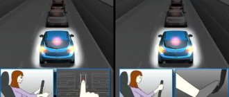
- several icons lit up on the dashboard at the same time for no reason - airbags, steering, pressure in the lubrication system, etc.;
- The Check Engine light appeared;
- There is no information on the control panel about the temperature of the power unit, the fuel level in the tank, speed, etc.
Reasons why malfunctions in the operation of the CAN interface may occur:
- broken wiring in one of the systems or damage to power lines;
- short circuit in the operation of the units to the battery or ground;
- damage to the rubber jumpers on the connector;
- oxidation of contacts, as a result of which signal transmission between systems is disrupted;
- discharge of the car battery or drop in voltage in the electrical network, which is associated with improper functioning of the generator set;
- closing of CAN-high or CAN-low systems;
- occurrence of malfunctions in the operation of the ignition coil.
The KV Avtoservis channel spoke in more detail about digital interface failures and testing using a computer.
Diagnostics
To determine the cause of the problem, you will need a tester; it is recommended to use a multimeter.
Verification process:
- Diagnostics begins with searching for the twisted pair conductor of the CAN bus. The cable has black or orange-gray insulation. The first is the dominant level, and the second is the secondary level.
- Using a multimeter, the voltage level on the contact elements is checked. When performing a task, the ignition must be turned on. The testing procedure will reveal voltage in the range from 0 to 11 volts. In practice this is usually 4.5 V.
- The ignition is turned off. The conductor with the negative contact is disconnected from the battery; first, use a wrench to loosen the clamp.
- The resistance parameter between the conductors is measured. You can know that the contacts are closed if this value tends to zero. When the diagnostics showed that the resistance is infinite, then there is a break in the power line. The problem may lie directly in the contact. It is necessary to check the connector and all wires in more detail.
- In practice, a short circuit usually occurs due to a breakdown of the control devices. To find a failed module, turn off each unit one by one and check the resistance value.
User Filat Ogorodnikov talked about diagnosing the CAN bus using an oscilloscope.
Filling into the controller
For CANNY controllers to work, before uploading the program (in the terminology of the “diagram” developers), you must first upload the operating system “Device/System Software/Write”. This only needs to be done once; to do this, you need to select the file with the .ccx .
Once the program has been written and debugged, it can be loaded into your controller. This is done simply - in the menu, select the “Device / Diagram / Write” item and after a few seconds the program is written to the controller.
How to make an analyzer with your own hands?
Only a professional in the field of electronics and electrical engineering can independently assemble this device.
Main nuances of the procedure:
- In accordance with the diagram in the first photo in the gallery, you need to purchase all the elements to develop the analyzer. The components are labeled on it. You will need a board with an STM32F103С8Т6 controller. You will need an electrical circuit of a stabilized control device and a CAN transceiver MCP2551.
- If necessary, a Bluetooth module is added to the analyzer. This will allow you to record basic information on your mobile device when using the device.
- The programming procedure is performed using any utility. It is recommended to use KANHacker or Arduino programs. The first option is more functional and has the option of filtering packet data.
- To carry out the firmware, you will need a USB-TTL conversion device; it will be needed for debugging. A simple option is to use ST-Link version 2.
- After downloading the program to your computer, the main EXE file must be flashed into the controller using a programmer. After completing the task, the bootloader jumper is installed, and the manufactured device is connected to the PC via a USB output.
- You can upload firmware to the analyzer using MPHIDFlash software.
- When the software update is completed, you need to disconnect the wire and remove the jumper. Drivers are being installed. If the device is assembled correctly, it will be detected on the computer as a COM port; this can be viewed in the task manager.
Photo gallery
Scheme for developing a CAN analyzer
Main board for device assembly
Practical examples
Let's use simple examples to see how to perform actions in CannyLab that are familiar to us in the Arduino IDE. Let's start with the traditional LED flashing.
In the CANNY 5 controller, there is a test LED at pin C4 (Channel 4) (analogous to the LED located at pin 13 in Arduino). And it can also be used for display and experiments, which is what we will use.
What is needed to blink the LED in the CANNY controller? You only need to do two things - configure the pin of the fourth channel as an output and apply a signal from the PWM generator to this output. We have already done all these actions more than once in the Arduino IDE, let's see how it looks in CannyLab.
So, let's configure the fourth channel pin as an output
Setting up a PWM generator. We set the period to 500 milliseconds, the filling to 250 milliseconds (that is, 50%) and 1 (true) at the “Start” generator input and... that’s it! There is nothing else you need to do - the program is ready, all that remains is to upload it to the controller.
Pros and cons of CAN buses
Advantages of the digital interface:
- Performance. The device can quickly exchange packet data between different systems.
- High resistance to electromagnetic interference.
- All digital interfaces have a multi-level control system. Thanks to this, you can prevent errors when transmitting and receiving information.
- During operation, the bus itself spreads the speed across the channels in automatic mode. This ensures the efficient operation of the vehicle's electronic systems.
- The digital interface is secure. If someone tries to gain illegal access to the electronic components and systems of the car, the bus will automatically block this attempt.
- The presence of a digital interface makes it possible to simplify the installation of a security system on a car with minimal interference in the standard on-board network.
Disadvantages of the CAN bus:
- Some interfaces have restrictions on the amount of information that can be transferred. This drawback will be significant for a modern car, “stuffed” with electronics. As more devices are added, a higher load is placed on the bus. Because of this, response time is reduced.
- All packet data that is transmitted over the bus has a specific purpose. A minimal portion of traffic is allocated for useful information.
- If a higher level protocol is used, this will cause a lack of standardization.
High level protocols
CAN just solves the problem of delivering information from one point to another, in small packets (only 8 bytes). Many aspects of data exchange remain beyond his competence. Due to the great demand in the market, the development of improved protocols - the so-called high-level protocols - immediately appeared. They undertook to provide a more expanded package of services. They are used when needed:
- Set launch standards, incl. exchange speed;
- Distribution of previously recognized addresses of interacting elements and types of messages;
- Accurate message markup;
- The order of error analysis.
Video “Do-it-yourself CAN interface repair”
User Roman Brock talked about the procedure for restoring the dashboard tire in a Ford Focus 2 restyling car.
Do you have any questions? Specialists and readers of the AUTODVIG website will help you ask a question
Was this article helpful?
Thank you for your opinion!
The article was useful. Please share the information with your friends.
Yes (50.00%)
No (50.00%)
X
Please write what is wrong and leave recommendations on the article
Cancel reply
Rate this article: ( 8 votes, average: 4.50 out of 5)
Discuss the article:
please clarify on RX/TX
Please clarify what these symbols are and what kind of connection they are. and is it possible, without connecting this only, to train the key without a hunter on the Prado.
Answers 24
Then maybe it’s better to go to the installers after all?
aleksjud,
Have you decided to also install alarm systems in addition to your main job profile? Or have you been doing this for a long time, but then came across a new product?
Without these signals, BYPASSING the standard immo will not work.
Good luck in your professional growth.
majorov61 thanks for the direction. As I understand it, I’m looking at the kan table if there’s a check mark in the column, bypassing the standard immo. and there is an alarm with a kan and lin module. then everything can be connected. Am I right or wrong?