The ability to reliably block the engine from starting in the event of an alarm is necessary for the alarm system. Another thing is that it is not so easy to block the engine correctly: by modern standards, it is considered necessary for the car thief to spend at least half an hour bypassing the protective circuits. Therefore, it is not without reason that it is said that an alarm installer must think like a thief: when installing an alarm, the first question he asks himself is “how can it be turned off or bypassed?”
Main starter relay
The car's electric starting system includes, in addition to the starter and relay, also starter on/off elements, various connecting wires, the main power source (battery), etc.
The starter relay or VR is activated after turning the key in the ignition switch. The BP armature and the freewheel lever move, and the bendix engages with the flywheel crown. This ensures normal engine starting.
To be able to adjust the system, you need to disconnect the current wiring from the VR. The control terminal is marked on the terminal with the letter M.
Then the battery is removed from its original place and connected to the M and S terminals marked on the terminals. Thus, the purpose of the operation performed is to shift the bendix. And in order to connect the BP to the starter, you must first adjust the gap between the bendix and the stop. It is also recommended to adjust the gasket located between the drive and the BP.
Additional VR starter
On modern cars, an additional VR starter is a priori provided. On older cars, the relay is installed and connected independently.
The advantages of installing an additional VR are obvious:
- Protects the starter device from burnout of contacts in the lock, which occurs for various reasons (long start-up, banal wear, etc.);
- It has a positive effect on the loading of contacts of the same ignition switch, as a result of which the contacts remain operational longer;
- Protection of the starter from a situation where, due to a “glitch” of the key in the ignition switch (the engine has started, but the starter continues to spin).
You can check whether the additional VR is installed on the car like this:
- Look in the “black box” (fuse box);
- Turn on the starter device in the engine purging mode - if the additional relay is on, then the starter must turn off on its own after a few seconds.
Connection of additional VR
Here's how to connect:
- Fix the relay in any convenient place (you can on the stud of the glass cleaning fluid reservoir);
- Connect the cable to the starter;
- Remove the red wire from the flat terminal of the main relay, and in its place insert the wire from the additional VR;
- Connect the other wire of the new BP with an 8 mm tip to the positive of the starter;
- Place contact 30 of the additional VR onto the released contact of the main VR;
- Screw the short wire numbered 85 to the body (ground).
Additional relays can be purchased in stores. They are sold as a kit, where everything is provided for proper self-installation.
Forget about fines from cameras! An absolutely legal new product - NANOFILM, which hides your license plates from IR cameras (which are installed in all cities). More details at the link.
- Absolutely legal (Article 12.2.4).
- Hides from photo and video recording.
- Installs independently in 2 minutes.
- Invisible to the human eye, does not deteriorate due to weather.
- 2 year warranty
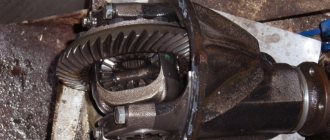
Gear starter for MTZ
The design of the gear unit is distinguished by the transmission of torque from the armature through a built-in gear reducer, which, with its gear ratio, increases the torque power to the diesel flywheel. This design of the unit has a smaller electric motor part, thereby reducing the cost of production of the unit. The idea of the design is to reduce the use of expensive electric steel, magnets, and copper in assembly parts during production and increase the profitability of sales.
For the consumer, the advantage is a lower consumed discharge current and a lower voltage drop in the network during startup, taking into account the increase in power due to the mechanical part of the unit. The use of a unit of this design has a positive effect on the battery charge life, which is important when starting is difficult in the cold season.
The market offers a number of units for MTZ 82 by the following popular brands:
- Slovak - Slovakia
- Atek - Belarus
- Jubana – Lithuania
- Magneton – Czech Republic
To eliminate biased assessments in the comparison of the above brands, we will not fall into a useless assessment based on a number of reviews on the Internet. Often, buyers' impressions can be based on the purchase of counterfeit units of low quality that discredit a particular brand. To select a unit, we will indicate a number of criteria that ensure the acquisition of a high-quality starter.
Criteria for choosing a starter
Today, the qualitative differences and advantages of components of absolutely all brands are determined by the quality of assembly parts manufactured to order in China. Each brand adheres to its own marketing strategy in sales, which determines the price level, service, technical and quality level of the units offered.
Starter relay description purpose device repair photo video
Share “Starter relay description purpose device repair photo video”
The movement of any car begins with starting the engine . If you want to understand the principles of operation of the main components of a car, we recommend starting your study with the starting system. One of the most vulnerable points of this system is the starter relay. Almost everyone has heard about this detail, but not many understand the principle of its operation. Before we start talking about the starter relay, it is worth noting that the design of the car simultaneously has two parts with the same name, only the first is responsible for turning on the starter, it is usually located in the engine compartment, and the second is the starter solenoid relay.
Starter for tractors Belarus MTZ 82(80)
The power unit in the electric starting system is the starter. Depending on the type of starting system on the MTZ 82 tractor, electric starters are used both to start the PD 10 starting engine and directly to start the diesel engine. As for the starter start of the launcher, we note that they use units of the ST 352 D, ST 362A brands with a power of 0.6 hp. The article will focus on the components installed for electric starting of a diesel engine: their varieties and technical characteristics, advantages and disadvantages, causes of operational problems, features when choosing and purchasing a component.
WHAT IS A STARTER RELAY
So, let's start with the basics. Two relays are responsible for the starter. The first is installed in the engine compartment. The design can have its own housing or be installed in a common unit.
In this article, we will be much more interested in the second relay, which is responsible for the operation of the starter, namely the retractor. It performs the following functions:
- redistributes energy between the starter and the electromagnetic relay;
- feeds Bendix gears;
- synchronizes the starter components,
- returns the gears to their original position after you turn off the engine.
In the automotive world, this unit has two names: traction and retraction. The first is most often used in specialized literature, the second is popular.
To understand why a starter solenoid relay is needed, let’s look at the engine’s operation schematically. To start the engine, the crankshaft must begin to rotate. Only after this does the fuel-air mixture ignite in the combustion chamber.
Usually the engine starting process takes place within a second. The role of the relay in it is quite simple. Thanks to it, the gear elements engage with each other. It synchronizes the operation of the starter. This unit also removes the bendix from the flywheel.
Starter start of the MTZ 82(80) tractor
The starter, in the factory configuration, is located on the left side of the machine and is flanged to the rear plate of the diesel engine with three bolts. The unit is a four-pole sequential excitation DC electric motor, consisting of: a housing, a stator, a rotor-armature, a brush holder, a solenoid switch, an overrunning clutch and a drive gear. MTZ 82(80) is standardly equipped with a ST 212 A unit with a power of 3.2 kW (4.5 hp), operating from the tractor’s standard network voltage of 12 volts.
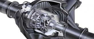
Main components and operating principle of the engine starting system
To understand the operation of the starting system, it is worth first considering the design of the car starter. The purpose of the starter is to start the engine. The starter device for all cars is identical, they differ only in size or parameters. So, the design consists of the following required elements:
- Electric DC motor;
- Bendix;
- Starter solenoid relay.
The main role here is played by the electric motor, and the bendix and starter relay are auxiliary elements. The electric motor includes standard elements such as a stator, a rotor, and a starter brush assembly. Bendix, even the smallest detail, plays a very important role. It is necessary to transmit rotation from the electric motor to the gear ring of the engine flywheel, thereby ensuring starting.
Until 2000, the bendix was located on the same shaft as the rotor, and then a new arrangement appeared, where the bendix began to have its own separate shaft and rotate through a gearbox.
That’s why we sometimes hear the name “gear starter”. The starter retractor relay is a more complex element and performs several functions at once:
- Redistribution of electricity supplied from the battery between the electric magnet of the starter relay and the electric motor;
- Synchronization of the operation of all components when starting the engine;
- Feeding the Bendix gear until it engages with the flywheel ring gear;
- Returning the working gear to its original position after starting the engine.
The principle of operation of the starter is as follows: in order to start the car engine into operating mode, it is necessary to forcibly rotate the crankshaft until the fuel mixture in the cylinders begins to burn.
Typically, it takes quite a bit of time to start a working engine. The task of the starter retractor relay is to maintain the engagement of the Bendix gear with the flywheel and rotate the crankshaft equally until the start occurs. No more and no less. If you hold it longer, you can break parts, and if you hold it longer, the engine won’t start.
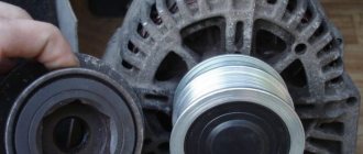
Starter components. What is this made of...
Starter consumables:
Brushes
The brushes are made of copper-graphite material (there are from 2 to 6 of them in the starter - positive and negative), and they are attached to the brush holder (a metal structure with a textolite plate that separates the positive brushes from the negative ones).
Bushings
The bushings also consist of copper-graphite material, only in a different proportion.
Nickels (extractor relay contacts)
The contacts are made of copper material with a perfectly smooth surface in the contacting area.
Consumables 2-long lasting:
Bendix
Bendixes come in different designs. And their similarity is that all bendixes have a mechanism due to which the bendix rotates in one direction, but does not rotate in the other. Also, most Bendix engines have a gear that meshes with the engine.
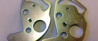
Solenoid relay
The starter solenoid relay (electromagnet) usually consists of two coils (holding and retracting windings), a core, two contacts, a rod, a brass bushing, a spring, a contact bolt, a textolite cover, a contact disk and a relay body. Solenoid relays come in two types - collapsible and non-removable.
Bearings
You can find a bearing in the starter on the bendix (not in all models), on the armature (rotor) and for alignment in the front or rear cover of the starter.
Plunger
The plunger is used as a separate spare part in a dismountable solenoid relay. This is the rod-core of an electromagnet with a contact round washer.
Reducer rubber bands
These are seals that reduce noise and vibration in the metal gearbox during starter operation.
Planetary gear mechanism
This mechanism is found in gear type starters. The planetary can be metal or made of a special plastic material.
Starter fork
The starter fork is involved in the “ejection” of the Bendix. It is mainly made of a special plastic material, but there are also metal forks.
Rotor (armature)
The starter armature consists of a rod, in the front of which there are splines or teeth for connection to the gear part of the starter. A copper winding is wound around the rod and connected to a commutator (copper lamellas) at the rear of the rotor; the rear starter cover with brush holder is attached to this side.
Stator (winding)/magnetic cup
There are two types of starter stator - winding (copper wire wound with oval rings (there are 4 oval rings in total). This wire is tightly attached to the cup (starter body). The second type of stator is magnets of different polarities attached to the starter cup.
Starter front cover
To make the starter front cover (starter mask), duralumin and its alloys or cast iron are used. The starter cover can be closed or open.
Starter rear cover
For the manufacture of the starter back cover, duralumin and its alloys, as well as metal alloys, are used.
Retaining ring
Hardened steel is used for the retaining ring.
Pinch bolts
Pinch bolts are made of steel
Gearbox
The gearbox consists of a metal rod with splines, satellites and a planetary gear mechanism (sometimes plastic).
If you find an error, please select a piece of text and press Ctrl+Enter.
DIAGNOSTICS AND REPAIR
CHECKING THE SYSTEM
Before checking the solenoid relay, you need to test the starter itself. This check will allow you to understand what exactly is not working in the system. Insert the key into the ignition and turn it.
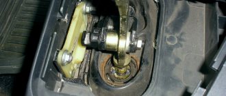
Next you will need to open the hood and get to the starter. You must make sure that this is the case. To do this, bridge the two contacts. They are made in the form of two copper bolts. These structural elements are attached to the rear of the solenoid relay (on the body). If, after the manipulations you have performed, the mechanism rotates, then the problem is in the solenoid relay.
In some cars, reaching the starter is very difficult, and sometimes even impossible. In this case, you will have to partially disassemble the system and dismantle the device itself.
After removing the starter, place it on the ground. Place the battery nearby. Connect the leads of the two devices. In this case, the battery ground is connected to the starter ground.
When the wires are connected, the starter solenoid relay will operate. At first there will be a rather loud click. If the mechanism operates too slowly, be sure to check the contacts. This situation may be caused by the fact that they are burnt.
First signs of concern:
- The starter does not start immediately, but after several test turns of the key. This indicates burning of the solenoid relay contacts. To eliminate the problem, you need to clean the contacts.
- The starter mechanism rotates, but it is too slow, and the battery is fully charged. In this case, you need to pay attention to wear of the brushes or wear of the bearing device.
- After the engine starts, the starter does not immediately turn off. This means wear on the gear teeth in the bendix or the flywheel ring.
Checking the retractor relay with the starter removed
It is more convenient to check the functionality of the relay with the starter removed. But before dismantling, several operations are performed to identify the problem:
- Check the reliability of the terminals, the condition of the battery, remove oxides from the contacts and terminals of the battery.
- Make sure that the wiring is securely fastened to the starter with nuts. If corrosion is noticeable, clean the contacts with fine sandpaper.
- Check the condition of the starter enable relay.
The starter is removed after disconnecting the wires that go to it and unscrewing the mounting bolts. In some cars, this operation will take a lot of effort, since the unit may be located in a poorly accessible engine compartment.
After removing the starter, it is cleaned of dirt, the oxidized contacts are treated with sandpaper, and the test begins in the following order:
- The unit is placed next to the battery, from the terminals of which there are wires with “crocodiles”.
- The positive and negative terminals are connected to the corresponding contacts on the retractor.
- The free end of the negative wire is touched to the starter housing and the result is observed:
- If there is a distinct click in the relay, then it is working;
- If the retractor does not show “signs of life,” it needs to be replaced or repaired.
WHAT DAMAGES CAN BE IN THE EXTRACTOR RELAY
Usually the whole problem lies in burnt contacts or their sticking; other faults include:
- coil burnout,
- mechanical damage,
- natural wear and tear of parts.
In the latter case, the starter solenoid relay will need to be replaced. There are a number of signs that most likely indicate that the problem is in this particular node, these include:
- After the engine starts, the starter continues to operate. This is indicated by a clearly audible buzzing sound.
- When you turn the key in the lock, you can hear a distinct clicking sound. This means that the main system starts, but the starter does not work.
- When you turn the key, the starter idles. The engine remains inactive.
These signs most likely indicate that the malfunction is related to the starter solenoid relay.
HOW TO CONNECT
Many motorists are afraid that after they repair the solenoid relay, they will not be able to connect it. In reality, the connection diagram is quite simple. Moreover, you compose it yourself.
To carry out reverse dismantling, you must first mark the disconnected terminals. This will allow you to connect everything correctly after the repair is completed. Also, before installing the relay, you need to clean the contacts. For degreasing, use a modern liquid sold in automotive stores.
REPAIR
It is worth recognizing that on machines of the same series, the starter solenoid relays are very similar. The most striking in this context is the following automobile line:
In principle, all starter solenoid relays have the same design. Accordingly, their repair process is similar. The main differences lie in the fastening systems. Also, cores can have different designs. But the general scheme is very similar.
So, in order to repair the starter solenoid relay, you first need to dismantle and disassemble it. Here, in fact, lies the main problem. In most cars, these units are non-separable. All that remains for the driver in this case is to make a replacement.
This is interesting: Installation diagram of window lifter cables for UAZ loaf
It is very important to maintain a clear sequence during repairs. Otherwise, you risk not only damaging the part or other systems, but also getting injured. The process itself consists of the following stages:
- Disconnect power from the battery.
- Clean the part from dust and dirt. Otherwise, foreign particles may get inside the unit, causing damage to it.
- Unscrew the brush assembly nut.
- Remove the contact from the bolt.
- Unscrew the clamping screws. They are the ones that connect the relay to the ground of the car.
- Unscrew the ends of the nuts.
- Divide the device in half.
- Replace the core.
- Reassemble.
Before putting the device back into the car, start it. Reinstallation should only be carried out after preliminary testing. Once everything is assembled, do a few test runs. Only after this go on the road.
WHAT ELSE CAN BROKE?
Most damage to the solenoid relay is associated with the burnout of certain of its elements. Most often, electromagnetic circuits burn out. Windings and contacts are also subject to similar destruction. In some cases, the cause of failure is metal fatigue.
However, ignition problems are not always associated with the starter or solenoid relay. If the repair does not give the desired results, check the electrical circuit. Also look at how much charge the battery has.
Every car owner can check and repair the solenoid relay. The process itself does not take much time, and its complexity in most cases depends on how conveniently the starter is located.
Share “Starter relay description purpose device repair photo video”
Types of mounting blocks
VAZ 2110 has 2 types of mounting blocks:
- basic;
- additional.
The first contains most of the fuses and relays in the vehicle's power supply circuit. The second one houses the devices responsible for the motor power supply circuits. Over time, the main block experienced a number of transformations and modernizations - there were three in total. The main difference between them is the number of relays. From the first models to today, it has grown from six to eight.
New mounting block
The area required updating with each modification of the VAZ 2110. It was necessary to correct some design flaws that were noticeable from the very beginning. The fog lamp fuse did not have a circuit board and was hanging on a bundle of cables next to the mounting block itself.
The first change in the layout of the main mounting block occurred precisely in connection with the placement of a fog lamp fuse in it, as well as an increase in the number of relays. In the updated modification of the latter there are not 6 or 7, but 8.
Particular variability in new block modifications is associated with the presence or absence of the K1 front light relay: some models have only legs and jumpers that require cutting when installing K1 yourself, or just the legs, without jumpers. In other modern units they also install the relay itself.
Old style mounting block
There are six relays and 20 fuses. Its location is the same as that of modern models. Over time, another relay was added, responsible for the front light. Otherwise, its design is no fundamentally different from subsequent ones.
Car starter connection diagram
A lot of time has passed from the time the car was created, or rather the introduction of a starter into it, to the present day, but the scheme has remained virtually unchanged. The first connection diagram for the starter looked approximately as shown in the figure below, now it has changed a little, which I will explain below.
The battery positive (1) is connected by a thick wire to the starter terminal (3). The starter current at start-up can reach hundreds of amperes. Next, the plus, through the generator (2), is supplied to the ignition switch (5). After closing the ignition switch contacts, the intermediate relay coil (4) is energized, which closes its contacts. One of the relay contacts is connected to the positive wire, therefore, after their closure, the windings of the solenoid relay are energized. We will look at how the starter and solenoid relay work in another article.
Such schemes were used in Soviet-made cars; foreign cars, if they used them, moved away from such schemes very quickly. The first starters were massive and had low efficiency. Consequently, the control circuits required the same not small currents. An intermediate relay is used to pass these currents. Modern starters have less power. This was achieved by using permanent magnets on the stator poles and installing a step-down gearbox on some models. This made it possible to get rid of the intermediate relay and supply voltage from the ignition switch directly to the coils of the solenoid relay.
Computer keyboard circuit Starter blocking device Simple starter blocking Power supply for 9-volt radio equipment from the car's on-board network Circuit of a desulfating charger Simple stabilized power supply with super-available parts Laboratory power supply controlled by a microcontroller Laboratory power supply from an AT power supply Power supply from an uninterruptible power supply
Fuses and relays for the Belarus MTZ-82.1 tractor
Electrical fuses are designed to protect against overloads and short circuits in electrical circuits.
Molded Panel Instrument Fuses
Three fuse blocks for electrical circuits are mounted in the instrument panel with a molded panel. To access the fuses located in the instrument panel of the Belarus MTZ-82.1, 80.1, 82.2 tractor, you need to unscrew screw 2 and fold back panel 3.
Fig.29. Access to fuses located in the instrument panel with molded panel
1 – instrument panel; 2 – screw; 3 – panel.
Fig.30. Fuses located in the instrument panel with molded panel
Purpose of instrument panel fuses with molded panel
1 - 15A - Brake lights, terminal (6) and terminal (8) trailer socket. 2 - 15A - Road train sign lights (if equipped), rear work lights, cabin lighting. 3 - 15A - Hazard warning lights. 4 - 25A - Front and rear windshield wipers, front window washer. 5 - 15A - Sound signal. 6 - 25A - Main beam of road headlights, signal lamp for turning on the main beam of headlights. 7 - 25A - Front working lights, signal beacon (when installed). 8 - 25A - Power supply for the heater fan control circuit or power supply for the heater fan 80-8101720. 9 - 25A - Power supply for consumers operating when the starter switch and devices are in the "devices on" position: devices, speed sensors, power supply to fuse 15 and 16. 10 - 25A - Power supply for the electric motor of the fan-heater (when installing the fan-heater 80- 8101720 this fuse is not used); 11 - 7.5A - Left side parking lights, trailer socket terminal (7), license plate lighting. 12 - 15A - Side lights on the starboard side, terminal (5) of the trailer socket, instrument lighting. 13 - 7.5A - Low beam of the left road headlight. 14 - 7.5A - Low beam of the right road headlight. 15 - 7.5A - Power supply for instruments, speed sensors, warning lamp units, emergency sound alarm (buzzer) and parking brake relay breaker. 16 - 15A - Turn signal relay, glow plug block, glow plug relay coils.
Molded Panel Instrument Fuses
Three fuse blocks for electrical circuits are mounted in the instrument panel with a molded panel (installed upon request to replace the panel with a molded panel). To access the fuses, unscrew two screws 2 and open the cover of the instrument panel 1.
Fig.31. Location of fuse boxes in a molded panel instrument panel
1 – instrument panel cover; 2 – screw.
Fig.32. Placement of fuses in the instrument panel Belarus MTZ-82-1, 80-1, 82-2 with a molded panel
Assignment of molded panel instrument fuses
1 - 15A - Brake lights, terminal (6) and terminal (8) trailer socket. 2 - 15A - Road train sign lights (if equipped), rear work lights, cabin lighting. 3 - 15A - Hazard warning lights. 4 - 25A - Front and rear windshield wipers, front window washer. 5 - 15A - Sound signal. 6 - 25A - Main beam of road headlights, signal lamp for turning on the main beam of headlights. 7 - 25A - Front working lights on the roof, signal beacon, working lights on the handrails (if equipped). 8 - 25A - Power supply for the heater fan control circuit or power supply for the heater fan 80-8101720. 9 - 25A - Power supply for consumers operating when the starter switch and devices are in the "devices on" position: devices, speed sensors, power supply to fuse 15 and 16. 10 - 25A - Power supply for the fan-heater (when installing the fan-heater 80-8101720 this fuse is not used); 11 - 7.5A - Left side parking lights, trailer socket terminal (7), license plate lighting. 12 - 15A - Side lights on the starboard side, terminal (5) of the trailer socket, instrument lighting. 13 - 7.5A - Low beam of the left road headlight. 14 - 7.5A - Low beam of the right road headlight. 15 - 7.5A - Instrumentation, warning lamp block, speed sensors, alarm sound alarm (buzzer). 16 - 15A - Power supply for the turn signal switch, power supply for the glow plug control system, glow plug relay coils.
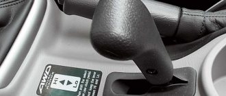
How to make a start button instead of an ignition key in a car with your own hands
Oddly enough, this issue very often worries motorists and not only for aesthetic reasons - in the spirit of the times. The contact group located behind the ignition key very often fails, and changing it is far from an easy task.
In older cars, often the wires from the starter itself are connected directly to contacts inside the contact group, which close when the ignition key is turned. When the starter is activated, a very large amount of energy is consumed, which means a large current flows (the contacts strike a spark). Over time, a burnt deposit forms on the contacts or they completely burn out, no longer providing reliable contact. Newer vehicles have a separate relay that closes the starter contacts when the ignition key is turned.
The main advantages of using a relay in the starter power circuit:
— Such a system is more reliable, since the relay is designed for high currents and lives much longer. — The relay can always be replaced — The contact group behind the ignition key works for a very long time, since it only turns on the relay that takes the main load.
Regardless of whether your starter is turned on by a relay or directly by a contact group, all operations to connect the starter are still performed by turning the key.
First you need to determine which contacts are responsible for the start and connect them to the start button.
To do this, you need to disassemble the plastic protection under the steering wheel of your car. Very often, a connector with all the necessary wires is connected to the contact group of the key well at the back. There should be locking tabs on both sides of this connector. You need to press on them and pull out the connector.
If you have an old car, inspecting the contact group connector you will most likely find the two thickest wires. Very often one of them is red - these wires are directly connected to the starter. If you connect them with the ignition key turned, your starter will most likely start spinning.
Then you can go the simple way. You can simply install the button and connect these two wires to it, placing the button in a place convenient for you. The button should be non-latching, that is, when pressed, it should close the contacts, and immediately after you release it, open it.
Do not forget that you will operate the button in the same way as a key. We press the button, wait until the starter spins, and as soon as the engine starts, release the button.
But do not forget that very large currents will pass through the button and most likely such a button will burn out.
We used a vandal-proof chrome button - it failed after about half a year.
If you have a newer car and the starter in it is connected using a relay, you will need to find among the many wires exactly those that are responsible for controlling the relay.
To do this, you can ring the tester in resistance measurement mode on all the wires on the car body. All wires that ring are marked as ground (or minus), since they are all shorted to the body.
Next, touch each of the remaining wires with one tester probe and the other probe to the body in voltage measurement mode.
We need to find the wire on which 12 Volts appears exactly at the moment you turn the key, that is, when your starter starts spinning.
If you find this contact, you need to check how the system works.
— Find some kind of contact on which, relative to ground, there is always 12 Volts.
— Turn the ignition key to ignition mode (the starter must be turned off)
— Check again the wire you found:
* check that it is not connected to ground and is not short-circuited to the body,
* check that voltage appears on it when you turn the key to the starter mode
- Now try using a separate wire to connect the wire that you found in the paragraph above to the wire that always has 12 Volts.
If after connecting your starter turns over, then you have found the wires that connect when you turn the key so that the starter turns over.
Your work is finished here. You just need to bring these wires to a convenient location on the dashboard and connect the button to them.
If your car is an old model, it is best for you to install a separate relay to turn on the starter and close only the relay contacts, which in turn will connect the starter contacts.
You can see which contacts are responsible for what on the relay body, or you can open it and see how it works.
Oddly enough, it makes absolutely no difference where to connect + (plus) and where - (minus) on the contacts of the relay coil - in any case, it attracts the desired contact and connects the line.
That is why you can use the positive contact with 12 Volts already connected to the relay. It can be connected to the coil contact. Accordingly, the second contact is connected to ground through the button.
It is these two wires - minus (ground) - the second contact of the coil that must be brought out in a place convenient for you and the button connected to them.
The remaining relay contacts for the main line must be connected to the wires on the contact group that connect the starter.
Don't forget about high power when connecting these wires. The wires must be very thick and the connections very secure.
The wires can be directly soldered to the relay contacts, but most likely this will be a mistake, since it will be quite difficult to replace it later. In our case, when heating the contacts with a soldering iron, they melted the plastic body of the relay and moved, closing the contacts inside the relay.
It is best to find a remote connector for such relays, which is sold separately. Unfortunately, it does not please with its reliability or quality of workmanship.
The wires on the connector pins are very thin and very difficult to hold on to. We recommend that you remove each pin and solder secure thick wires to them.
For convenient connection, you can attach screw terminals to the wires.
It is best to place the relay in a place where it will be convenient for you to reach it later to replace or check the operation of the system.
Remember that you do all the above actions at your own peril and risk; we do not recommend that you undertake such complex electrical work if you do not have skills in electrical engineering. We wish you good luck in all your endeavors.
Typical faults
Among all the problems that happen with the starter, most are associated with this traction relay. Let's look at the most common faults.
During operation, the starter experiences enormous loads. Most often it is installed at the bottom of the engine. This is an area that receives a large amount of dust and dirt, water, and other liquids. Structurally, the retractor relay is combined with the starter housing. If we take into account the location of the relay, it also experiences serious loads. Inrush currents when starting the engine can reach up to 500 A and above. This leads to destruction of the contact pads, contact plate and contact bolts.
Among the main malfunctions are breaks, destruction or burnout of the windings. Also, contact zones on the heels and contact plate are often destroyed. The contact bolt clamps are burning. Often the plug breaks, the relay rod or armature gets stuck. The springs are destroyed.
How to connect a starter relay: rules for connecting a relay
As you know, normal functioning of a car is impossible without a good and clear start. When setting up the electric starting system of a car, great importance should be paid to the “starter-relay” circuit. It is important to know how to connect the starter relay so that no difficulties arise in the entire starting system.
Main starter relay
The car's electric starting system includes, in addition to the starter and relay, also starter on/off elements, various connecting wires, the main power source (battery), etc.
The starter relay or VR is activated after turning the key in the ignition switch. The BP armature and the freewheel lever move, and the bendix engages with the flywheel crown. This ensures normal engine starting.
How to properly connect the starter relay
To be able to adjust the system, you need to disconnect the current wiring from the VR. The control terminal is marked on the terminal with the letter M.
Then the battery is removed from its original place and connected to the M and S terminals marked on the terminals. Thus, the purpose of the operation performed is to shift the bendix. And in order to connect the BP to the starter, you must first adjust the gap between the bendix and the stop. It is also recommended to adjust the gasket located between the drive and the BP.
Additional VR starter
On modern cars, an additional VR starter is a priori provided. On older cars, the relay is installed and connected independently.
The advantages of installing an additional VR are obvious:
- Protects the starter device from burnout of contacts in the lock, which occurs for various reasons (long start-up, banal wear, etc.);
- It has a positive effect on the loading of contacts of the same ignition switch, as a result of which the contacts remain operational longer;
- Protection of the starter from a situation where, due to a “glitch” of the key in the ignition switch (the engine has started, but the starter continues to spin).
This is interesting: Wiring diagram for VAZ 2114 power windows
How to connect the additional starter relay
You can check whether the additional VR is installed on the car like this:
- Look in the “black box” (fuse box);
- Turn on the starter device in the engine purging mode - if the additional relay is on, then the starter must turn off on its own after a few seconds.
Connection of additional VR
Here's how to connect:
- Fix the relay in any convenient place (you can on the stud of the glass cleaning fluid reservoir);
- Connect the cable to the starter;
- Remove the red wire from the flat terminal of the main relay, and in its place insert the wire from the additional VR;
- Connect the other wire of the new BP with an 8 mm tip to the positive of the starter;
- Place contact 30 of the additional VR onto the released contact of the main VR;
- Screw the short wire numbered 85 to the body (ground).
Additional relays can be purchased in stores. They are sold as a kit, where everything is provided for proper self-installation.
How to pay TWICE LESS for GASOLINE
- Gasoline prices are rising every day, and the car's appetite is only increasing.
- You would be happy to cut costs, but is it possible to live without a car these days!?
But there is a completely simple way to reduce fuel consumption! Don't believe me? An auto mechanic with 15 years of experience also didn’t believe it until he tried it. And now he saves 35,000 rubles a year on gasoline! Read more about this at the link.
What does it mean “the starter takes over the current”?
The main reasons why the starter can take on current are:
- Lack of good contact on electrical wiring and elements of the ignition system;
- Sufficiently low electrical or high mechanical resistance;
- Failure of the constituent elements (due to the deterioration of the bushings, the armature begins to touch the starter when rotating). This leads to strong heating and destruction of parts. The gearbox also needs to be checked, because it may also need additional lubrication.
Your actions
To understand the true reason, it is necessary to carefully study the mechanism and check all its elements. The first step is to determine the location of this mechanism. Access to it is usually very limited, but you can get it by hand. It is also important to make sure that the battery is charged, since drivers often leave the car with the headlights on, and their work greatly drains the battery.
If the battery is in perfect order, then you should check the starter, for this you will need a power class=”aligncenter” width=”600″ height=”402″[/img] So, a thick wire is supplied from the battery to the starter, which is connected to a large bolt on relay (this is the positive terminal). You need to connect the positive contact of the multimeter to it, as a rule, this is the red wire. And the black wire with a negative contact must be connected to the ground of the car. And when you turn the key in the ignition, check what the instrument display shows. If the battery is working well, the voltmeter will show twelve volts, and the starter will make characteristic clicks. If clicks occur and the display shows less than twelve, then perhaps the reason is not in the starter, but in the battery or ignition switch.
To check the malfunction, you need to purchase a long screwdriver with a well-rubberized handle. Next, you need to disconnect the wire that comes from the ignition switch from the solenoid relay. Next, you need to short-circuit the positive terminal with the bolt from which the wire was removed, using the metal part of the screwdriver. This operation will allow current to be supplied directly from the battery to the relay. The car should start. If you managed to do this, then this means either the lock or the relay is faulty.
If you were unable to perform such a manipulation, this check did not produce any results, then you will have to remove it and deal with it. Before checking the relay, it must be cleaned of various contaminants. Next, connect the starter to the battery. We connect the positive contact of the battery to the relay output, and the negative contact to its body. As a result, a click should occur and the gears should begin to move. This way we know that the relay is working properly. If this operation does not produce results, then the relay must be repaired yourself or purchased a new one. The cost of the relay is not high. If you buy a new one, do not forget to buy the same one (go to the store with the old relay).
After checking the relay, I recommend checking the starter itself. There is a terminal in the place where the relay was; you need to connect the positive alligator clip from the battery to it, and the negative one to the housing. If the gear works, then the reason is in the relay. The second element that may cause poor starter performance is its armature.
The fact is that in a situation where the bendix rotates very slowly, and the battery is fully charged, it is necessary to remove the armature. Next, you need to check the housing winding and the winding short circuit - these are the main reasons for the failure of the starter armature. To check the functionality of this element, you need to use a tester and check the voltage between the windings and the rotor housing. The tester should show at least a million ohms, or even more. If the data is lower, the anchor needs to be replaced.
From my experience I know that checking the bendix, brushes and windings play an important role in the good performance of the machine. If the relay does not work, then it is necessary to check the brushes and the winding. To check, you need to use a regular light bulb (12 Volts) with two wires that are connected to the brush holder and to ground. When checking, the starter must be connected to the battery. If the lights come on, this means that the brushes are faulty. In the same way it is necessary to check the winding.
It is important to remember that if several starter elements break down at the same time, it is advisable to purchase a new one rather than try to replace one part at a time.
If one part fails, then it needs to be replaced. The new part must be identical to the part being replaced. It is not advisable to purchase analogues; this may lead to undesirable consequences in further work.
Video “Checking current leakage”
The recording shows how you can check at home whether there is a current leak on a JEEP car.
List of reasons
This is mainly a consequence of the following breakdowns:
- nuts are not securely fastened. It is possible that they were completely unwinding. To eliminate it, you just need to strengthen the fasteners by tightening the nuts;
- connection points, wires have undergone oxidation. If this is minor, then such places simply need to be cleaned. If the process is significant, a complete replacement is required;
- there is a break in the power supply. This must be eliminated by replacing the wires;
- If the device responds too slowly, it needs to be replaced.
In order to check the winding turns, you must use an ohmmeter.
When checking the solenoid relay, the following algorithm is used:
- First, you need to provide access to the starter. It is located next to the gearbox and is located slightly lower than the battery.
- The voltage needs to be checked. It should not be higher than 8 V.
- The moment of operation is accompanied by a certain temperature. If it is above 25 degrees, then you cannot expect effective operation from the device.
Some deficiencies can be detected directly by visual inspection. Once detected, they must be eliminated.
Dismantling steps:
- First, the battery wire with the minus sign is disconnected;
- then the air filter must be removed;
- All wires are disconnected from the solenoid relay;
- the tip of the power cable is disconnected. To do this, you need to unscrew the nut using wrench No. 13;
- the nuts that serve to fix the trigger device are unscrewed. For this, wrench No. 15 is used. But it should be said that this nut is not so easy to get to;
- then the starter must be removed;
- wiring is disconnected;
- the relay is dismantled using key No. 8.
If someone has a desire to repair the relay, then from a theoretical point of view this is quite possible. But there is no economic feasibility. The part is very inexpensive and it is easier to simply replace it. Moreover, there is currently no shortage of spare parts. In any case, the new element will work much longer than the repaired part.
We can only hope that those who read this article have acquired new knowledge and now know where the starter relay is located on a VAZ 2110.
How to hook up a button to the starter via a relay and connect
Today, drivers of old cars often want to see a convenient button on the instrument panel that can easily activate the starter. They want such modernization not only for aesthetic purposes, but also for purely practical ones. We will learn from the article how to connect a button to the starter via a relay.
Contact vulnerability
In cars manufactured more than ten years ago, the starter wires are always connected directly to the ignition switch contacts. The engine starts only after the driver turns the ignition key to the extreme position.
This option for connecting the starter is simple and effective. But contacts are always a problem. Moreover, when the starter device is activated, a huge amount of voltage is generated, causing sparking. Where there is a spark, the contacts burn out, oxides accumulate on them, etc. As a result of this, over time, problems arise with starting the engine; motorists are looking for alternative ways to turn on the starter, including directly from the battery.
How to connect a starter via a relay
As you know, in cars of recent years of production, which do not have a button, an additional relay is provided that controls the starter. In this way, the lock contacts are relieved, which now bear less of a load.
- Systems with a separate relay are more reliable because they last longer.
- The ignition switch contacts also “live” much longer.
- An additional relay can always be upgraded.
How to connect a button to the starter
However, the topic of this article is connecting the starter via a button connected to the same relay. How can this be accomplished?
Connecting a button in a car where there is no additional relay
First of all, you should find the contacts responsible for turning on the starter. Then integrate them with the button.
The modernization algorithm generally looks like this:
- The plastic trim under the steering wheel is disassembled;
- There is a connector connected to the ignition switch contacts (as a rule, this connector has locking tabs);
- Press the tabs to release the connector and pull it out.
As a rule, on older cars, after inspecting the connector, two cables with a large cross-section are found. The red one is responsible for controlling the starter.
Note. You can check whether the wiring is really responsible for controlling the starter like this. Turn the ignition key all the way, short-circuit both wires from the removed connector. If the starter turns on, then that's what they are.
- The button is placed in a place convenient for the driver;
- The found wires are connected to it.
The most common breakdowns
The starter of the VAZ 2114 does not turn.
One of the most common problems is the loosening of the fastening of the power wire tip. Simply tighten it and check all the other nuts at the same time. The second popular reason for the failure of this unit is considered to be oxidation of contacts. If you notice a problem at an early stage, then just clean the contacts and the unit will work properly. If cleaning doesn't help, you will need to replace them.
Oxide often occurs on the winding, making it impossible to block. You can try to clean the winding, but experienced motorists recommend replacing the relay immediately, this way you will be able to drive your car much longer without problems.
Another probable cause of problems with starting the engine is a break in the retractor power supply circuit. You will have to find them and fix the problem. Find the broken wires and place new ones in their place. Upon completion of work, check the relay power circuit again. One way to check the functionality of a disassembled relay is to check it with an ohmmeter. To do this, you need to place the probes of the device on the turns of two windings.
Sometimes it is enough to replace the anchor. This must be done when it operates slowly or is idle. These signs directly indicate a malfunction of the anchor itself. It will be quite difficult for a car enthusiast with little experience to identify problems with this element.
Repairing a relay is more expensive than replacing it, so the easiest way is to immediately replace the faulty part. This will save your time, because it is unknown whether repairs, which are often very labor-intensive, will help. An attempt to restore the unit is fraught with danger - if the relay is repaired incorrectly, you can be left without a car for a long time, since engine starting will be blocked. In this case, you will need to carry out more complex repairs, which cannot be carried out without the participation of specialists.