Many car enthusiasts like to carry out tuning of various kinds. Recently, the installation of a crankcase gas oil separator has become widespread. It is especially popular among fans of fast driving. In stores, they will ask for 2000 rubles for such a device, if not more. However, why pay if you can make such a necessary device yourself?! But first you need to figure out why it is needed at all. Maybe the engine is fine without it? But there are some peculiarities that this article is devoted to.
Oil Trap Installation
The installation has its own characteristics and depends on the type of engine used in the car. So, if it works using injection technology, the device is connected to the inlet pipe, which is located in front of the throttle valve and the cylinder block cover.
If the car is equipped with a carburetor engine, the oil trap connection is made directly in front of the air filter, which is responsible for regulating crankcase emissions.
That's it, the device is ready for use. However, it is worth noting that one installation is not enough and for high-quality and productive operation of the oil trap, it should be periodically inspected and maintained, approximately once every two months. To do this, the element is disconnected from the system and pulled out from its place. Next, it must be thoroughly washed, completely cleared of any oil accumulated inside and treated with a solvent, then installed back and connected.
Oil leakage negatively affects both the quality of engine operation and its service life. Using an oil trap allows you to solve the problem to a certain extent, however, the quality of the oil itself also plays a very important role here. You should not save money by choosing cheap and untested samples; the engine does not like it when people skimp on it, remember this.
Summing up
Well, the creation of an oil trap with your own hands is over. As you can see for yourself, there is nothing complicated in this procedure and anyone can cope with it. Fortunately, no special knowledge or specialized equipment is required here. At the same time, despite its apparent simplicity, the device copes with its duties perfectly, protecting the engine and extending its service life.
Good luck with your renovation.
How to make an oil trap yourself
I decided to post my oil catcher, otherwise there is a lot of incomprehensible information on the internet
They show the finished version, but the most important thing is that it doesn’t show how it works inside. A more correct option is this
The exhaust gases must rise from below and pass completely through the scrapers. You can buy ready-made branded ones, but the cost is surprising.
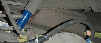
They also put the tube outside, but you don’t want to breathe gases when the car is warming up, stuck in a traffic jam, or when you turn on the heater in winter.
I put it in my VAZ 2105, drove it 100 km and put it in for repairs, I need to do the engine. It is clear that oil was thrown into the carburetor before the oil sump was installed, now it will be interesting with the new engine how the oil catcher will work.
I created the diagram myself.
mesh so that the scrapers do not fall down into the emulsion
ordinary stainless steel scrapers
At the outlet of the oil catcher, I put a brush in the tube to make sure nothing gets into the carburetor.
List of parts for a homemade oil trap:
- a metal jar with a lid (you can use a jar of pineapples or baby food);
- two corner brass adapters with threaded edges;
- the hose is like a crankcase gas nipple;
- the tube is slightly less than the depth of the jar;
- metal sponges, I used 3 of them but I’m thinking of adding a couple more (I took some old ones from the kitchen);
- silicone or sealant;
- a plastic bottle with an uneven bottom (from Coca-Cola or similar);
- old car wheel tube;
- clamps and other small things.
So what is an oil trap?
An oil catcher, also called an “oil catcher,” is a device for additional separation of oil emulsion; in simple terms, the system is designed to clean the air from particles of engine oil, which can rise from the crankcase along with crankcase gases as a fine suspension and oil mist.
Oil evaporation can occur for various reasons, but, in particular, this phenomenon may be due to low-quality lubricant, which will begin to evaporate at operating temperatures. In this case, oil combustion products will settle on the intake manifold, throttle valve, idle air valve, etc., polluting some internal parts of the engine and complicating the operation of the engine as a whole.
Custom made oil catcher
photo: lada-xray2.ru
Thus, the oil trap acts as a kind of filter that protects the engine from excessive contamination by crankcase gases and maintains its operating parameters by condensing oil vapors entering the intake system and then being sucked into the combustion chambers.
It is because of this oil mist on cars that it is recommended to clean the throttle body!
Over time, a film forms on the back of the damper, facing the engine, and then a whole thick layer of “oil” deposits, which is mainly the fault of the engine crankcase ventilation system.
The larger the layer of oil on the damper, the worse its response to opening and closing the throttle, “freezing” after releasing the gas pedal. Rough operation at idle.
We already told you how you can clean a mechanical throttle valve by cleaning it from this state:
Bringing him to this:
You can read more here:
It is precisely this kind of deposit throughout the intake manifold that the oil gas separator is designed to combat.
Alternative solutions for crankcase gas filter
There are several options. The first is to simply bring the hose with crankcase gases outside, but here you will need to install a filter so that when air is drawn in from the external environment, dust does not get into the crankcase. The hose going to the intake manifold inlet will need to be plugged in this case.
The second option is to use a filter, which should be installed between the crankcase pipe and the intake pipe. This filter is used on some machines as standard, but not on all.
(standard oil trap with Ford Focus 2)
Apparently the ubiquitous savings are making themselves felt. And if this is so, then you have the opportunity to improve your car a little. By limiting the entry of crankcase gases with oil vapor into the throttle assembly, without associated cleaning.
As you understand, we offer you to solve the issue of filtering crankcase gases with your own hands. Next we will talk about these options...
Operating procedure
You don't need any special tools for assembly. Everything you need is available in every garage. The work is carried out in the following order:
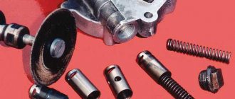
- The tank is disassembled
. Contents are extracted from it. The filter and 2 springs (large and small) can be put aside; they will not be needed; - We insert a tube with a diameter of 14 mm into the body; it should go down to the very bottom. So the gases will pass through the entire jar without exception;
- We take sponges and, after fluffing them, fill the jar with them. After that, we put a washer and a cotter pin, in the end we get this kind of filter;
- We take the mesh that was in the tank and make a hole for the tube. Then we install it in place;
- The next step is optional. You can paint the jar any color (at your discretion). But this will not affect performance;
- While the reservoir is drying out, it makes sense to clean the throttle valve from dirt; for this you can use any available method;
- We install it under the hood. We connect the hose from the breather to the terminal with a long tube, and attach the hose going to the throttle to the main one.
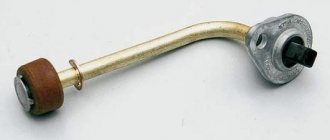
Design, purpose and principle of operation of the hydraulic arrow
The hydraulic arrow for heating consists of a bronze or steel body with two pipes for connecting to the boiler circuit (supply pipe + return pipe), as well as several pipes (usually 2) for connecting the heat consumer circuits. An automatic air vent is mounted in the upper part of the hydraulic separator through a ball valve or shut-off valve. at the bottom there is a drainage tap. A special mesh is often installed inside the housing of factory hydraulic arrows, which allows small air bubbles to be directed into the air vent.
Design of the Valtec VT model. VAR 00.
The hydraulic arrow for heating performs the following functions:
- Maintaining the hydraulic balance of the system. Turning on/off one of the circuits does not affect the hydraulic characteristics of the remaining circuits;
- Ensuring the safety of cast iron boiler heat exchangers. The use of a hydraulic arrow allows you to protect cast iron heat exchangers from sudden temperature changes (for example, during repair work, when the circulation pump is turned off, or when the boiler is turned on for the first time). As is known, a sharp change in coolant temperature negatively affects cast iron heat exchangers;
- Air vent. The hydraulic arrow for heating performs the functions of removing air from the heating system. To do this, in the upper part of the device there is a pipe for installing an automatic air vent;
- Filling or draining coolant. Most of both factory-made and self-made hydraulic switches are equipped with drain valves, through which it is possible to fill or drain coolant from the system;
- Cleaning the system from mechanical contaminants. The low flow rate of the coolant in the hydraulic separator makes it an ideal device for collecting various mechanical contaminants (scale, scale, rust, sand and other sludge). Solid particles circulating through the heating system gradually accumulate in the lower part of the device, after which they can be removed through the drain valve. Some models of hydraulic arrows can be additionally equipped with magnetic catchers that attract metal particles.
Diagram of a heating system using a hydraulic separator.
Advice! It is recommended to install the magnetic trap before the system is filled with coolant; otherwise, when installing the trap, it will be necessary to drain the water from the hydraulic separator.
The process of removing mechanical particles through the drain valve:
- Turn off the boiler and circulation pumps;
- After the coolant has cooled, shut off the section of the pipeline where the drain valve is located;
- We put a hose of a suitable diameter on the drain tap, or, if space allows, we substitute a bucket or any other container;
- Open the tap and drain the coolant until clean water comes out without any contaminants;
- Close the drain valve, and then open the blocked section of the pipeline;
- We subscribe the system and launch the equipment.
Relevance
Why do you need to install such a clever device? Due to high crankshaft speeds, oil flies through the crankcase ventilation breather and can end up on the carburetor assembly, and in the case of injection engines, on the throttle unit. And to prevent this from happening, just such a device is installed. Moreover, it is advisable to install it not only for those drivers who do not mind pressing the accelerator pedal to the floor. Those owners who have been using their car for quite a long time should also think about it. After all, during this period, the rings have most likely already worn out and do not provide proper sealing of the combustion chamber.
What is engine oil starvation?
Due to insufficient lubrication, the aluminum almost melted
For obvious reasons, if there is no lubrication in the rubbing units, they instantly fail. The danger of oil starvation
motor is that it can occur instantly and almost completely destroy the main components of the engine:
crankshaft, camshaft, gas distribution mechanism, cylinder-piston group, and other vital and expensive components and assemblies.
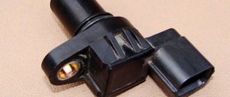
Broken camshaft key (due to insufficient lubrication)
Out of the blue!
Oil starvation does not occur out of the blue
, and as a rule, all the blame for a breakdown lies only with the owner of the car or the mechanics who made the repairs. As you know, oil is in the crankcase in the quantity required for lubrication and is supplied to the system using an oil pump. In the case when the oil cannot reach individual rubbing units, oil starvation occurs. There can be a lot of reasons for this.
Main characteristics
| Make: BMW | Gearbox: automatic / manual |
| Model: X1 | Body: sedan, coupe, station wagon |
| Year of issue: 2009 | Power: petrol/diesel |
| Engine capacity: 1985 cm³ | Drive: rear |
–> Good afternoon, Friends!
I would like to share with you my experience in making an oil trap and crankcase gas filter with my own hands, using the example of a VAZ 21102 produced in 2000.
First, a small digression, for those who do not know why this modification is needed.
Many car owners, both domestic and foreign cars with high mileage, have more than once paid attention to oil deposits in the form of a plasticine-sticky mass (which appears when crankcase gases with droplets of oil escape, due to wear of the oil scraper rings, from the “breather”) in the intake path, as well as on the throttle valve, intake manifold, idle air valve, oil also flows into the air filter through the mass air flow sensor (MAF), which can lead to failure of the mass air flow sensor (replacement cost is about 2500-3000 rubles) . And so, if you are tired of suffering from idle problems and constantly carrying out preventive work on cleaning the intake manifold, throttle assembly and changing various sensors, which, firstly, not everyone can do due to lack of knowledge, and secondly, it is necessary a lot of time, tools and of course money
In general, to avoid all of the above, you can install a crankcase gas filter or an oil trap, which can also be bought at a tuning store at a fairly decent price, or you can make it yourself. We will dwell on the latter, that is, the manufacture of an oil trap (crankcase gas oil trap), in detail.
So, to make a crankcase gas filter we will need:
– a hose with a diameter approximately similar to the hose of the interior heating system and a length of about 25-30 centimeters;
– fine fuel filter without settling tank for carburetor cars,
– plastic clamp for the filter.
First, we disconnect the hose from the valve cover and from the intake tract, you need to make any plug for the hole remaining in the intake tract (I took a technological plug from the new VUT), then we take a hose of the required length (depending on the location of the filter), I took about 30 centimeters, so that the filter is at the level of the air filter housing, we put it on the valve cover fitting and fix it with a clamp, then from the fine fuel filter housing, you need to take out the filter element and put it on the hose, securing it with a plastic clamp.
Now, when crankcase gases escape, the oil will remain inside the filter.
Symptoms of a Stuck PCV
- Engine misfires at idle
- Lean air-fuel mixture
- Presence of engine oil in PCV valve or hose
- Increased oil consumption
- Hard engine start
- Rough, unstable engine operation at idle
Additionally, a stuck PCV valve can cause a check engine light due to increased air flow. And the diagnostic computer may mistakenly show this error due to the mass air flow sensor or oxygen sensor, making it difficult for you to identify the real source of the problem.
Assembly technology
This process is not particularly difficult. First of all, you need to install a plug on one side of the coupling. You will get something resembling a very ordinary glass. For greater reliability, it is recommended to seal the plug with sealant - no one will remove it in the future.
We place a metal sponge on the bottom of the coupling, without completely filling the cylinder. We drill two holes in the top plug - the diameter is the same as that of the prepared pipes. We process their edges with silicone grease, and then install them in the holes so that when viewed from the inside, one of them is approximately 1 cm shorter than the second. The longer pipe will be used for inlet.
We seal the top cover with a rubber gasket. The assembly of the gas recovery device is complete.
If desired, you can paint the resulting unit and, after waiting for it to dry completely, proceed to installation.
Separators with magnetic traps
Pneumatex separators with magnetic traps (DN 20 – DN 400 mm) trap insoluble iron impurities in water much more effectively than conventional separators. The rod(s) with a powerful magnet are inserted from below from the outside into the separator sleeve and removed before the operation of washing out the sludge without violating the tightness of the system. The magnetic rod is separated from the water by the walls of the sleeve and does not require cleaning or protection from corrosion. The sleeve is made of non-magnetic material, so the magnetic particles quickly settle down and then the sludge is washed away through the valve. For effective flushing, the valve is offset from the center (creating a vortex effect). Separators with magnetic traps also contain conventional separating elements and have all the degassing and non-magnetic particle removal properties of conventional separator models.
Main characteristics
| Make: BMW | Gearbox: automatic / manual |
| Model: X1 | Body: sedan, coupe, station wagon |
| Year of issue: 2009 | Power: petrol/diesel |
| Engine capacity: 1985 cm³ | Drive: rear |
–> Good afternoon, Friends!
I would like to share with you my experience in making an oil trap and crankcase gas filter with my own hands, using the example of a VAZ 21102 produced in 2000.
First, a small digression, for those who do not know why this modification is needed.
Many car owners, both domestic and foreign cars with high mileage, have more than once paid attention to oil deposits in the form of a plasticine-sticky mass (which appears when crankcase gases with droplets of oil escape, due to wear of the oil scraper rings, from the “breather”) in the intake path, as well as on the throttle valve, intake manifold, idle air valve, oil also flows into the air filter through the mass air flow sensor (MAF), which can lead to failure of the mass air flow sensor (replacement cost is about 2500-3000 rubles) . And so, if you are tired of suffering from idle problems and constantly carrying out preventive work on cleaning the intake manifold, throttle assembly and changing various sensors, which, firstly, not everyone can do due to lack of knowledge, and secondly, it is necessary a lot of time, tools and of course money
In general, to avoid all of the above, you can install a crankcase gas filter or an oil trap, which can also be bought at a tuning store at a fairly decent price, or you can make it yourself. We will dwell on the latter, that is, the manufacture of an oil trap (crankcase gas oil trap), in detail.
So, to make a crankcase gas filter we will need:
– a hose with a diameter approximately similar to the hose of the interior heating system and a length of about 25-30 centimeters;
– fine fuel filter without settling tank for carburetor cars,
– plastic clamp for the filter.
First, we disconnect the hose from the valve cover and from the intake tract, you need to make any plug for the hole remaining in the intake tract (I took a technological plug from the new VUT), then we take a hose of the required length (depending on the location of the filter), I took about 30 centimeters, so that the filter is at the level of the air filter housing, we put it on the valve cover fitting and fix it with a clamp, then from the fine fuel filter housing, you need to take out the filter element and put it on the hose, securing it with a plastic clamp.
Why is the PCV valve important?
Faulty PCVs can cause engine oil contamination, sludge buildup, oil leaks, high fuel consumption, and other engine damage problems, depending on the type of fault.
While some of these problems can be caught before they escalate with simple checks, failure of the PCV valve or related components often results in costly repairs. This is because most car owners do not include the PCV system in their maintenance routines. Even though some car manufacturers suggest replacing this part regularly, car owners still forget to replace it. Additionally, not all manufacturers emphasize the importance of regular system checks.
More information about JTlab oil traps
An oil trap (oil washer) is a device for condensing oil vapor from the crankcase gases of an engine. Oil traps are designed to sift out (condensate) oil vapors and then collect them or drain them into the oil system of the internal combustion engine. On most conventional engines, crankcase gases are supplied directly to the combustion engine intake or turbine intake for TURBO engines. In this case, oil condenses in the intake manifold, cylinder head passages, cold part of the turbine, piping, intercooler, sensors and throttle valve. Over time, fine dust adheres to a thin layer of oil, and after several tens of thousands of kilometers, all parts of the intake system are covered with a layer of a thick mixture of oil and dust. This scheme has a lot of serious disadvantages - oil reduces the efficiency of the intercooler, leads to contamination of the turbine, intake, cylinder head channels, piping, leads to problems in the operation of the throttle valve, idle speed regulators, worsens sensor readings, but most importantly, oil can provoke detonation, which is a disaster for the internal combustion engine.
On powerful tuning ATMO and TURBO engines, oil traps (oil washers) are installed, which separate the oil from the crankcase gases, eliminating all the shortcomings of the system. With this scheme, crankcase gases with oil vapor first enter the separator (oil sump), where, due to various physical principles and design features, the oil is separated from the gas flow. After separation, the oil flows back into the engine crankcase, and “dry” toxic crankcase gases are supplied to the intake and burned in the engine. Moreover, most factory engines use a positive pressure system in the crankcase of the internal combustion engine, which means that when the piston moves down, it has to overcome the force of this pressure, this state of affairs increases losses and reduces the efficiency of the internal combustion engine. Open and closed type oil washers solve this problem as well. An open-type oil sump is an oil separator, from which crankcase gases are removed directly into the atmosphere; a closed-type oil sump feeds crankcase gases back into the engine for combustion (environmentally friendly type).
Usually, an oil sump is considered to be just a jar with fittings, empty inside, this type does not work well and only collects condensation of water and oil; it is dangerous to use oil sumps of this type in winter.
We have been working on our own design of oil sumps for several years now. Our early designs worked perfectly all year round on TURBO and ATMO engines, did not require maintenance or periodic drainage of condensate, and removed up to 90% of oil from crankcase gases. But as soon as we began assembling engines for high boost 2+ bar, the issue of quality and performance of the oil sump arose with renewed vigor.
The new design of the high-performance oil sump was developed using CAD technologies, including modeling of gas flow processes and oil/water condensation. Thanks to this, a special design of the internal structure of the oil sump was developed, which retains low resistance to gas flow and high separation efficiency, allowing up to 95-98% of oil to be captured from crankcase gases.
The photo below shows several pictures visualizing the oil separation processes inside our oil sump.
breather VAZ 2112 16 valves - hello. thank you very much. I have a VAZ 2112 - 22 answers
In the Service, Maintenance, Tuning section, hello to the question. thank you very much. I have a VAZ 2112 asked by the author Ask for the best answer It may have overheated and the rings are stuck.
Reply from 22 replies Hello! Here is a selection of topics with answers to your question: Hello. thank you very much. I have a VAZ 2112 Reply from Alexander Sudorgin overfilled the oil Reply from Eurovision On the upper plane of the head, the valve drive parts are fixed, which are covered with a lid with a cap. A breather is mounted on the cap. It communicates the crankcase cavity with the atmosphere. The breather is necessary to prevent oil from being squeezed out through the crankcase seals by gases penetrating from the cylinders. Air and gases that have escaped from the cylinders into the crankcase come out through the breather. If, after stopping the engine, the pressure of the cooled air in it becomes below atmospheric pressure, the air enters the crankcase from the outside through the breather. Wire packing soaked in oil cleans the air of dust. In some engines, the breather is located on the side wall of the block (from the side of the rod chamber) or in the neck cover for pouring oil into the crankcase. Most car engines have forced crankcase ventilation. A pan is attached to the bottom plane of the crankcase, which serves as a reservoir. In general, check the oil level)) Answer from Ashera? Is this when they started installing the Priora engine on the VAZ 2112? 16 valves does not mean at all that it is a Priora one. And how did you notice this oil? The breather drives gases into the spider and not into the air vents. There are 2 breathers. Which one does it drive from? Most likely, the partition between the rings on one cylinder has burst. Answer from Theosophy: Check the crankcase ventilation system, there should be a primitive oil separator, so check it first of all with engine diagrams on the Internet, so start by studying the hardware.
The engine crankcase ventilation system 2111 of VAZ 2108, 2109, 21099 cars with fuel injection is designed to effectively remove gases from its crankcase and burn them in the combustion chambers. As a result, the emission of harmful substances into the atmosphere is reduced.
Design of the crankcase ventilation system for engine 2111 (diagram)
1. Engine crankcase.
3. Hose from the breather to the valve cover pipe.
4. Oil separator under the valve cover.
5. A thin hose from the valve cover to the fitting with the throttle body nozzle.
6. Fitting with a jet on the throttle valve block.
7. Thick hose from the valve cover to the inlet pipe.
Operating procedure for the 2111 engine ventilation system
— At idle, with the throttle valve closed, crankcase gases under high vacuum are sucked through the breather and its hose under the valve cover to the oil separator. Further, under the influence of the same vacuum, through a thin hose from the valve cover to the fitting with the nozzle into the throttle assembly, under the throttle valve and further into the combustion chambers (small branch). The jet limits the amount of crankcase gases entering at idle, as normal operation in this mode may be disrupted.
— In operating and power modes, when the throttle valve is slightly open and more efficient crankcase ventilation is required, crankcase gases also flow through the breather, its hose, to the oil separator under the engine valve cover. And then they are sucked through a thick hose from the valve cover into the intake pipe to the throttle body (large branch). Crankcase gases practically do not flow through a thin hose, since when the throttle valve is open, the vacuum behind it drops significantly.
Engine crankcase ventilation system malfunctions 2111
— The main and most common malfunction of the ventilation system is clogging. A clogged crankcase ventilation system can lead to negative consequences in the operation of the car engine. The hoses or oil separator or jet in the throttle assembly may become clogged.
The consequences may be the following:
— violation of the normal operation of the engine at idle (increasing the idle speed control steps more than normal - the speed increases);
— engine oil leaking from under the engine seals (as excess pressure is created in the crankcase);
— oil contamination of the engine air filter and, accordingly, a drop in power plus an increase in fuel appetite;
— contamination of the engine itself with tar deposits.
If, while operating a LADA car, you notice that during load (when the air conditioner is running, the heating is on, etc.) in a traffic jam, the engine begins to operate unstably (troits, pulls poorly, etc.), perhaps the reason lies in the ventilation system crankcase The article proposes to solve the problem by installing a PCV valve from a foreign car.
How does an oil separator work?
By cleaning the air returned to the intake system, the separator (installed on the crankcase ventilation pipe) reduces the amount of carbon deposits on the throttle body, spark plugs, valves and intake manifold, so the engine maintains optimal efficiency and does not lose power for a long time.
Among the options for separating crankcase gases from oil suspension, there are two most common ones. These can be like regular filter elements that use a fabric or metal filter.
Likewise, cyclone-type oil traps and centrifugal separators
Thanks to the separator, the engine intake system remains clean, which is especially important in cars with high mileage, as well as cars with a turbocharged engine and in power units that have undergone tuning modifications
For example, in the first case, oil is separated from gases due to the resistance of synthetic fabric or thin metal wire (over time, the internal filter element must be replaced or washed), but a centrifugal oil separator separates lubricant from gases in the following way: when passing through the device, gases and an oil suspension in they seem to “unwind”, exposed to centrifugal force; Thanks to this centrifugal force, the oil settles on the walls and flows back into the engine crankcase.
The cyclonic oil separator is equipped with a special valve that limits the vacuum in the engine crankcase, since strong vacuum can damage the engine boots and its rubber seals.
This is how the built-in filters provided by the internal combustion engine design work.
Engine crankcase ventilation system
As a rule, pistons fit tightly to the cylinder walls of the engine due to compression and oil rings. Despite this design of the piston group elements, it is impossible to ensure complete sealing of the combustion chamber. And some of the gases from the burned fuel still break into the crankcase, which is why they are called crankcase gases.
Moreover, depending on the design of the engine, 10-30 liters of gas can flow into the crankcase from just one cylinder in one minute. Due to the fact that the pistons move at high speed, the crankcase gases are constantly enriched with oil particles 0.1-2 microns in size. Oil mist is also formed due to the rotating crankshaft, which is immersed in an oil bath.
The problem itself is that the accumulation of gases in the crankcase leads to an increase in pressure that is exerted on the lubricant consumable. And in the absence of an oil separator for crankcase gases, this leads to an increase in pressure inside the lubrication system, and the oil puts pressure on weak areas, which are oil seals and seals. As a result, oil leakage cannot be avoided, and the engine becomes oil starved.
From a plumbing coupling
This option is also quite simple. The advantage of this device is the ability to drain oil, which extends the life of the filter element. To implement it you will need:
- Transition coupling (plumbing);
- 2 plugs;
- Adapter, fitting made of copper;
- Fitting gaskets;
- Nuts;
- Hose;
- Dish sponges.
Since you plan to drain the liquid, it makes sense to also purchase a faucet for the coolant. Assembly is carried out as follows:
- 2 holes for adapters are soldered into the plug; it is advisable to use sealant for reliability;
- Fittings are screwed into the adapters;
- A hose is installed from the return of one of the adapters. Please note that it is not advisable for it to reach the opposite plug by 12 mm;
- The plug and coupling are assembled, the jaws are placed inside;
- A tap is mounted on the opposite cover. With its help it will be possible to drain the oil collected there;
- We install the resulting device on the car.
Conclusion
Instructions for creating an oil trap for the Tavria ZAZ 1102 car
First of all, you should prepare the jar. We cut two holes in the lid with a diameter for threaded corner adapters. Then we screw them into the lid so that they stick out outside the jar. Apply sealant or silicone around the adapters to prevent gases from escaping.
After this, take a tube or hose, cut it to the depth of the jar, and make the bottom cut at an angle, then screw it onto one of the adapters under the lid. As you can see in the photo, I first tried to make an energy drink out of a can, but I gave up and took a can of infant formula from the times of the Soviet Union.
After this, we place the cut bottom upside down in the jar, insert the crusher with the hose inside, but at the same time push the metal jaws into it. We are closing this whole thing hermetically. Next, connect the hoses and clamp them with clamps.
Be careful, the hose coming from the engine must be connected to the adapter with a tube, and the hose that goes into the carburetor pan must be connected to the second adapter.
In order to prevent your can from rattling under the hood on bumps, I recommend putting a cut-off inner tube on it and wrapping it with tape or something for better fixation (if the inner tube does not fit tightly).
This is probably all that needs to be done to create an oil sump. For convenience, you can turn the nipple of the engine head cover with a knob in any direction. You can see the results of the oil sump by going HERE. The oil washer worked for 4 months, and see the results of its work there.
Cheap and cheerful, but functional
Many drivers who have already managed to make a crankcase oil separator on their own are pleasantly surprised by the price. In some cases it is practically zero. Perhaps craftsmen make do with improvised means that they find in their own garage. But even if nothing suitable is available, the price of the crankcase gas oil separator is low, since all the parts from the instructions discussed above are cheap.
On the Internet you can find many ways to make a homemade device, for which different materials are used. However, everything is done according to the scheme described above. Differences may relate to the use of additional elements or the replacement of plastic pipes with metal fittings that are screwed into the oil separator cover.
At the same time, there is a positive trend in engine performance. Oil no longer accumulates, which means you can drive for a long time without problems. However, do not forget to look under the hood of the car and check the condition of the device.
Is it possible to install an additional oil separating filter?
As you can see, this is a useful thing, especially when there is no time or desire to clean the throttle, change spark plugs and clean the intake manifold. However, not many automakers install such filters on their cars.
photo: www.drive2.ru
If there is no oil trap, you can install it additionally by first purchasing a ready-made one in the store (experienced users claim that they are ineffective) or make it yourself.
For an example of how this can be done, see here:
Video taken from the YouTube channel “Denis MECHANIC”
And more on the topic:
Video taken from the YouTube channel “Yuri K”
Instructions for creating an oil trap for the Tavria ZAZ 1102 car
First of all, you should prepare the jar. We cut two holes in the lid with a diameter for threaded corner adapters. Then we screw them into the lid so that they stick out outside the jar. Apply sealant or silicone around the adapters to prevent gases from escaping.
We cut off the bottom of the bottle, according to the picture below, and cut off a part on each cone.
After this, we place the cut bottom upside down in the jar, insert the crusher with the hose inside, but at the same time push the metal jaws into it. We are closing this whole thing hermetically. Next, connect the hoses and clamp them with clamps.
In order to prevent your can from rattling under the hood on bumps, I recommend putting a cut-off inner tube on it and wrapping it with tape or something for better fixation (if the inner tube does not fit tightly).
This is probably all that needs to be done to create an oil sump. For convenience, you can turn the nipple of the engine head cover with a knob in any direction. You can see the results of the oil sump by going HERE. The oil washer worked for 4 months, and see the results of its work there.
The features of a piston internal combustion engine require the removal of crankcase gases, due to the fact that the internal volume of the engine changes... The change in volume occurs due to the movement of the pistons, albeit to an insignificant extent, but still this phenomenon is observed. This effect is especially noticeable on “non-symmetrical” engines, that is, with an odd number of cylinders. As a result, the volume either increases, creating a vacuum inside itself, or decreases, increasing pressure. This effect can be easily corrected by simply communicating the crankcase with the external environment. But usually, manufacturers do not simply throw the hose with crankcase gases outside, but connect it to the engine power system, to the hose in front of the throttle assembly (throttle valve). Everything would be fine, but crankcase gases, as they should be, contain oil vapor. This means that when they get into the throttle assembly, and then into the combustion chamber, they clog the surfaces of the damper, pistons, cylinders, and spark plugs. All this is for nothing, to say the least. We need to get rid of this.
Alternative solutions for crankcase gas filter
There are several options. The first is to simply bring the hose with crankcase gases outside, but here you will need to install a filter so that when air is drawn in from the external environment, dust does not get into the crankcase. The hose going to the intake manifold inlet will need to be plugged in this case.
The second option is to use a filter, which should be installed between the crankcase pipe and the intake pipe. This filter is used on some machines as standard, but not on all.
(standard oil trap with Ford Focus 2)
Apparently the ubiquitous savings are making themselves felt. And if this is so, then you have the opportunity to improve your car a little. By limiting the entry of crankcase gases with oil vapor into the throttle assembly, without associated cleaning.
As you understand, we offer you to solve the issue of filtering crankcase gases with your own hands. Next we will talk about these options...
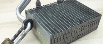
Oil in the air filter VAZ 2112
In normal condition, the air filter should remain dry after any period of use of the machine. If, upon opening the lid, you see oil stains on the filter itself, in the groove of the housing or in the crankcase, then urgent action must be taken.
There are several reasons for the appearance of oil:
- poor compression;
- use of additives;
- high oil level;
- wear of oil seals;
- burnt and sunken oil scraper rings;
- poor quality repairs at service stations;
- crankcase ventilation failure;
- valve adjustment is impaired;
- oil pump is faulty;
- clogging of the tubes from the upper valve to the injector;
- absence and malfunction of the oil trap in the corrugation.
Considering that the Zhiguli hatchback models differ only in the number of valves and the height of the head, oil accumulates in the air filter of the VAZ 21124 for the same reasons as in the base version of the car.
How to determine oil starvation
It was immediately clear that the engine was “starved of oil”
First, let's talk about determining engine oil starvation, since the range of symptoms is quite wide - from a drop in engine power to overheating, extraneous noise and knocking. All this indicates wear of certain components characteristic of each engine. For example, in the most common overhead gasoline engines, accelerated wear and increased noise during operation of the gas distribution mechanism are often encountered.
Consequences
In addition, the oil scraper rings may become stuck, which will lead to even greater excess oil consumption and engine seizure. Thick blue smoke from the exhaust pipe will indicate a malfunction of the oil scraper rings and high oil consumption.
Instructions for creating an oil catcher with your own hands for the Tavria ZAZ 1102 car
Hello everyone, dear subscribers and visitors of the site, today’s article will be about the oil trap for Tavria. I’ll tell you a secret, I made this device a long time ago, but I was able to write about it only now, after I analyzed its work.
So, what is an oil trap, or as it is also popularly called an oil sump?
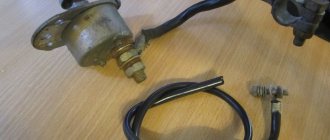
Everyone has probably already encountered the problem that after cleaning the carburetor regularly becomes dirty, the engine runs worse, and the spark plugs simply turn black, even though the oil seals and oil rings are intact. Also, in the so-called pan above the carburetor, white foam and oil constantly collect, all this enters it from the crankcase gas chamber in the engine head cover (see photo below). In the design of the Tavria car, the pan and the lid are directly connected by a hose, through which all the nasty stuff flies into the heart of our iron horse. Foreign cars use such a thing as an oil trap - this is a device that separates oil from the flow of crankcase gases, thereby filtering it.
I had a problem with carburetor contamination, which was very large hemorrhoids, since white foam was always in the pan, and accordingly the oil was also very unpleasant when the car is in this condition. You can see a photo of this horror below. Accordingly, this cannot result in ideal or even stable engine operation.
I struggled with this for a long time, changed the oil, blamed condensation inside the engine, etc., but in June of this year I decided to do an oil flush.
Having installed Recaro seats that day, I set about creating an oil sump with my own hands. For convenience, I will create a small list of parts that we will need for our oil sump.
A little theory
First, a little theoretical part. In any car engine, even a modern model, each system performs its duties, and there is nothing superfluous. Here we can draw a parallel with a person whose all organs are important and necessary. The main thing is to maintain a healthy lifestyle. Any car in this regard also needs regular maintenance.
The functions of all engine components and assemblies are constantly dependent on each other. And if a part breaks down in any system, the efficiency of the power plant is significantly reduced. The same applies to the crankcase ventilation system, in which a crankcase oil separator is simply necessary.
From a plumbing coupling
This option is also quite simple. The advantage of this device is the ability to drain oil, which extends the life of the filter element. To implement it you will need:
- Transition coupling (plumbing);
- 2 plugs;
- Adapter, fitting made of copper;
- Fitting gaskets;
- Nuts;
- Hose;
- Dish sponges.
Since you plan to drain the liquid, it makes sense to also purchase a faucet for the coolant. Assembly is carried out as follows:
- 2 holes for adapters are soldered into the plug; it is advisable to use sealant for reliability;
- Fittings are screwed into the adapters;
- A hose is installed from the return of one of the adapters. Please note that it is not advisable for it to reach the opposite plug by 12 mm;
- The plug and coupling are assembled, the jaws are placed inside;
- A tap is mounted on the opposite cover. With its help it will be possible to drain the oil collected there;
- We install the resulting device on the car.
Conclusion
. Over time, any car may develop a problem with oil escaping from the breather. Thus, the air filter and throttle body can become very dirty. Therefore, many drivers are interested in how to make an oil sump (crankcase gas oil catcher) with their own hands? In fact, setting up such a modification is not that difficult. The cost of such a device will be much cheaper compared to the purchased option.
Convenient and efficient oil catcher
A more reliable device can be made with your own hands. It’s easy to make, and you don’t need anything special for it:
- Metal power steering reservoir;
- A pair of hoses;
- Metal sponges for dishes (4 pcs are enough);
- Fasteners for the tank;
- Hose clamps.
These components are quite sufficient to create an oil catcher.
Manufacturing process
- We make a hole in the plug for a plastic pipe or fitting. We fix it on the plug and seal it. This will be the filter outlet.
- At the end of the sewer coupling, closer to the edge, a hole is made for the second pipe. We fix it on the coupling and seal it. This will be the inlet pipe from the crankcase.
- We stuff metal sponges inside the coupling as a filter element. They will trap dirt and oil capillaries. You should not tightly pack the jaws inside the coupling, as this will complicate the passage of air.
- We insert the plugs from both ends into the coupling; the joint can be additionally sealed.
Photo example of manufacturing:
Materials for a homemade filter
Assembling the housing with fittings
Primary filter housing
Primary Filter Media
Now assembling the filter
Place the filter in any convenient place. It is connected to the system through new rubber or silicone tubes. You can use old hoses, but then there is no possibility of installing the filter in a place convenient for the car owner.
Some craftsmen additionally install an external hydraulic level. It will show the level of oil accumulated in the filter. However, periodically checking the filter when changing the oil will not necessarily require this improvement.
Below is an example of making a crankcase gas filter from a brake fluid reservoir:
Finalization of the finished device
Not every car enthusiast wants to assemble an oil filter from scratch, or pay a large sum of money for a quality device.
In such cases, you can take the easier route and simply modify a ready-made, but budget-friendly oil catcher. To do this, just put on the tube for the inlet hose, disassemble the device and fill it with metal brushes. In this case, the soot will settle on them, which will allow you to use the filter several times, since replacing the brushes with new ones is quite simple.
Why you should never fill the filter with oil before installation Most car enthusiasts install the filter by first filling it with oil. This can be explained by the fact that...
The oil catcher not only collects oil from crankcase gases, but also allows it to be reused, which has a beneficial effect on the condition of the internal combustion engine and the environment. However, built-in devices for the most part cannot be cleaned and quickly become dirty. Therefore, almost every car owner knows that a production inertia filter does not bring any benefit and must be replaced after 500 thousand km.
The most common types of homemade dehumidifiers
Experts recommend using the following types of dehumidifiers:
- cyclone type;
- absorbing moisture using silica gel;
- refrigeration type.
Each type has its own advantages and disadvantages. To choose the best option for yourself, you need to familiarize yourself with all the device diagrams. The designs use old cylinders, oil filters, and refrigeration equipment elements. Before starting work, make sure that you have a welding machine, a set of keys and screwdrivers, a drill, a hammer, glue and insulating material.
Homemade cyclone-type devices
The operating principle of a cyclone dehumidifier is quite simple. When a stream of compressed air enters the installation, it begins to rotate. Under the influence of centrifugal force, condensate, small particles of debris and oil are directed towards the walls. At this time, the purified air passes into the lower central hole and is then supplied to the compressor.
The air mixture is supplied through the upper hole; under the action of centrifugal force, the moisture is separated and discharged through the outlet pipe
To create a homemade centrifugal apparatus we will need:
- old propane tank;
- union;
- welding machine;
- two metal tubes of short length.
An old cylinder is perfect as a body; it has sufficient height and can withstand increased pressure. The work order is as follows:
- We install the product vertically, with the tap down.
- We weld the inlet fitting to the top of the housing. It should be shifted closer to one of the walls of the cylinder. We weld the inlet fitting and the outlet pipe to the cylinder
- We weld the outlet pipe to 2/3 of the height of the cylinder. We install the cyclone moisture separator vertically, moisture will be removed through the lower hole with a valve
Silica gel dehumidifier
Silica gel allows you to filter the air mixture; you just need to correctly place a layer of this substance in the housing of the oil or water filter. Old equipment from Volga is ideal for creating a homemade dehumidifier.
- We disassemble the old oil filter. We disassemble the old oil filter and prepare it for further work
- As an inlet pipe, you can use the original tube through which oil was previously supplied.
- We plug the extra holes using bolts of the required diameter and sealant. To plug the holes we use bolts of the required diameter and sealant
- We reassemble in the reverse order, filling the free space with silica gel. We fill all the free space of the case with silka gel
- We put on the top cover and screw it tightly with a bolt. Press the top cover firmly against the oil filter housing
The filter design has several brackets, with the help of which the filter can be easily installed in the desired place.
Refrigeration device
As you know, low temperatures allow moisture in the air mixture to condense. Refrigeration type dehumidifiers are quite popular among auto mechanics. The devices cover almost all requirements for the air supplied to the compressor. When creating a dehumidifier, it is necessary to direct the air flow through the freezer or other refrigeration equipment.
It is important to completely seal the freezer in the receiver and make a pipe to drain condensate. For residents of the “cold” regions of our country, experts recommend supplying air to the compressor from the street
In winter, you will directly receive an air mixture with a low moisture content.
Separator device for waste water from continuous blowdown
The separator has a simple device; its body is made in the form of a vertical cylindrical container operating under pressure. Based on the permissible pressure, the bottoms of the housing are made flat or elliptical. The supply of purge water to the tank can have a flattened shape or a round cross-section.
Source of the diagram: cotlomash.ru
The flow of incoming hot water is swirled by supplying it to the wall of the separator tank, thanks to the placement of special guide devices inside. As a rule, the blowing flow rate to the separation device is set to no less than 1% of the steam output of the boiler unit.
At the very bottom there is a drainage fitting for periodically clearing the continuous blowing separator from sludge contaminants. The water level in the tank is maintained automatically by a float-type regulator.