On the entire family of carburetor cars "Samara 1" and on some carburetor cars of the family "Samara 2" (VAZ 2113 - 2115), two types of fuse blocks are installed, old and new. These devices are also called mounting blocks. They are the heart of the car's electrical system, because they are equipped with executive relays for low-current circuits. Using the mounting block, relays of high-current and additional circuits are also controlled - starter, fog lights, heated seats and others. The installation location of both units is the same, the difference is in small differences in the electrical circuit, different connectors and different arrangement of elements and a different housing design.
Location in the car
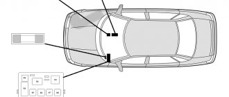
There are two types of location of turn signals in the classic VAZ family of cars, depending on the modification:
Let's start disassembling
- Early modification models
To get to the relay, you need to remove the plug by unscrewing the bolt on the dashboard.
We pull the entire panel towards us, move the sensor panel a little to the side so that we can get to the relay.
- The contacts approach the relay from below.
- Disconnect the contacts.
- We remove the old device and install the new one.
- We put the dashboard back, sliding it into the side grooves.
- Screw in the bolt.
We check the turn signals for flickering and characteristic clicks. The frequency of contact closure should be approximately 1 time per second.
The technology is very simple. The main difficulty here is accessibility to the relay. The space under the panel of these models is small, getting there is problematic.
- Later models
- Remove the screws from the steering column switch housing. We remove the casing elements.
- Unscrew the mounting bolt.
- We take out the devices on the electrical wiring inside the cabin.
- We replace the old relay with a new one.
- Screw it back. We put the covers in place.
When replacing any of the above relays, special attention should be paid to contact insulation. Insulation is carried out using hollow mass braid
To tie the wires, use a special strip clamp.
Why does not it work
The main reasons why the cigarette lighter on a VAZ-2109 stops working are:
- The fuse has broken. The maximum voltage that the connector can withstand is 20 A. But if you connect devices with high power to it, the fuse will stop functioning. In this case, the radio or the option responsible for heating the rear glass may stop working. To correct the situation, you will need to remove the front panel, find the burnt element and replace it with a new one.
- The wiring has broken. Long years of operation or illiterate interactions with the car's electrical circuit can cause short circuits, burnouts and wire breaks, which in turn causes problems with the cigarette lighter. To identify the problem, you need to take a multitester and ring the cables suitable for the device. If there is no power, then a break has formed, which can be corrected by replacing the wire.
- Burnout of the thermal coil located inside the device. Most often, the problem occurs due to prolonged use of the element. The breakdown cannot be repaired; the problem can be solved by replacing the device.
- Oxidation of contacts, which occurs due to the use of a more powerful fuse. It could also be a temporary defect. You can fix the problem by cleaning the contacts. Before carrying out the procedure, it is recommended to disconnect the terminal that is responsible for the negative (black wire) from the battery to avoid a short circuit.
- The backlight bulb has burned out. To fix the damage, you need to install a new light element.
Replacing fuses on a VAZ 2109
Preparatory stage:
- Plastic tweezers for removing the module;
- Rags;
- Additional lighting, provided that work is carried out in the dark.
Sequencing:
- We place the car within the perimeter of the repair zone;
- We turn off the engine, open the hood;
- Loosen the fasteners, remove the battery terminals;
- There is a mounting block on the left side, under the windshield; we snap off the plastic cover;
- We look at the inside where the fuse layout is indicated. We find the faulty one by the exact number or by a visual sign;
- We remove it with tweezers, insert a new one into its original place, and put on the lid.
In an old-style power supply, it is more difficult to identify a faulty module, since you need to remove each of the fuses one by one.
Upon completion, we start the engine and check that the systems are working properly.
Reasons for premature failure of fuses
- A natural factor is the duration of operation without intermediate prevention;
- Ingress of moisture, formation of condensation, oxidation of terminals, drying out of the insulating layer, open circuit of the electrical supply;
- Third-party mechanical damage, accident, impact, collision;
- Deformation of the car wing, windshield, which contributed to damage to the mounting block;
- Short circuit in the electrical supply circuit;
- Direct exposure to ultraviolet rays.
Subject to compliance with the manufacturer's operating recommendations, the fuse life is from 40,000 km. If you encounter any difficulties with installation, contact certified service stations or auto electricians for help.
Description of fuses
During the systematic operation of a technical device, due to weather conditions, fuses often fail, overheat, and become deformed.
To restore the performance of the car and its elements, it is necessary to replace the fuses (hereinafter referred to as modules) with new ones. The “update” process is not complicated, but requires care on the part of the repairman. Incorrect installation may damage the vehicle's electrical power system.
The VAZ 2109, as well as older models, has 16 modules and 12 relay switches preinstalled. This is in an old-style power supply unit. In the new PSU model, after 1998, the quantity also remained the same, although the craftsmen reduced the number by three modules.
- PSUs of the old type: they are marked 17.3722, structurally they consist of a plastic case, an engineering board to which the model wires and relays are soldered;
- New model power supply: 3722010-60, design in the form of a plastic case with pre-installed fuses.
Note to the driver. It is a misconception that the type of fuel injection system affects the PSU model. The mounting blocks for the carburetor and injector are the same.
Location: engine compartment, on the left side, under the windshield.
Dismantling and replacement
If one or another equipment fails, you must first check the condition of the fuse responsible for it.
In practice, removing and removing an unusable fuse or relay is not difficult. To do this you need:
- Raise the hood and disconnect the minus from the battery. Since you are working with the fuse box responsible for electrical equipment, the car should not be energized at this moment;
- Find the mounting block. It is located in the engine compartment opposite the driver's seat directly under the windshield. The top of the block is covered with a plastic cover. To remove it, simply press the latches on the sides;
- Remove the cover and look at the back side. There is an electrical diagram showing the location of one or another fuse or relay. Just find the element that is responsible for the failed equipment according to the tables above;
- Remove the fuse. All mounting blocks are equipped with special pliers. Manually removing fuses is not recommended. The relays are removed by gently rocking up and down;
- Replace the failed component.
Fuse failure is determined by the melted filament. These are fusible elements that melt and make contacts, preventing equipment from being damaged by excessive voltage.
That's it, all that remains is to replace the fuse block element, close the cover, replace the battery terminal and check the functionality of the equipment.
Do you know by heart the location of all fuses and relays in the VAZ 2109 power supply unit?
- Yes, I know everything.
- I only know the most basic ones.
- No, I use the power supply cover as my guide.
View Results
Loading …
What do you need to know about power supply maintenance and repair?
In terms of maintenance, the blocks are unpretentious. The car owner is recommended to periodically check the working condition of the safety elements. To do this, you need to open the cover of the unit, located in a special compartment behind the partition separating the car interior from the space under the hood. If burnt out components are found, these parts must be replaced. If you don’t have a whole device for this, then you need to purchase it. It is not allowed to install a piece of wire instead of a fuse. This may result in a short circuit and damage to wiring and equipment.
The device is located in a place where moisture can collect during rain. Water flowing down the windshield of the car enters the compartment in which the unit is installed. This compartment has a special drain hole for water, but its presence does not always help to avoid exposure to moisture on the power supply.
The VAZ 2109 channel published a video in which the assembly procedure of the safety block was demonstrated in detail.
How to remove, disassemble and repair a power supply if it fails as a result of exposure to moisture:
- Open the cover of the product, having first turned off the ignition and reset the battery terminal of the car.
- Remove one by one all the parts and relays mounted in the block. Remember their location or take a photo of the power supply so that you don’t confuse anything during installation. Please note that 5 A fuses cannot be replaced with 15 A devices.
- Unscrew the bolts that secure the block to the car body. The mechanism can be additionally fixed using sealant. In this case, it is necessary to remove its remains with a stationery knife.
- After unscrewing the bolts, pull the block out of the seat. To do this, you need to disconnect all the plugs with wires connected to it.
- When you have the block in your hands, visually assess the condition of its board. Prolonged exposure to moisture can cause mold to form on the circuit. You should try to clean the unit board with a dry cloth or a special product that can be purchased at the store. Contacts damaged by moisture must be resoldered. To do this you will need a soldering iron with rosin and tin. After the contacts are re-soldered, the block is mounted in place. Also evaluate the condition of the plugs on the cables connecting to the device. If the contacts are damaged by moisture, they will need to be replaced.
- After installing the device in the mounting location, place all the parts, connect the battery and check the operation of the repaired product.
User Ivan Saichenko in his video showed how to solve the problem if all instruments and equipment in a VAZ 21099 car completely failed.
Where is the fuse for the VAZ 2115 stove?
Where is the VAZ-2115 heater fuse located?
It is difficult not to notice when the heater in a VAZ-2115 does not work, especially if the heater breaks down in the winter. What malfunctions can be imagined if a cool air flow leaks into the car interior or there is no heated air flow at all?
There are several circumstances that can stop the operation of the VAZ-2115 stove, including a malfunction of the fan fuse. To repair a fuse, you need to know exactly where it is located. This will be discussed below.
Causes of malfunction of the VAZ-2115 stove fan
The VAZ-2115 stove is a complex mechanism, where a malfunction of at least one part can lead to a complete lack of heating of the car’s interior. To find the correct operation of the fan, start the VAZ-2115 and switch the speed position to format from 1 to 3 inclusive.
Pay attention to the occurrence of noise. When the fan is functioning adequately, the noise should be
But if the fan is not operational at speeds 1, 2, but turns on at speed 3, then the problem is in the resistor or switch responsible for controlling and setting the heating intensity mode of the stove.
The condition of the VAZ-2115 stove fan leaves much to be desired for the following reasons:
- There is a bad contact in the mounting block. Such a contact must be painstakingly cleaned of traces of oxidation or completely replaced with new wiring. To identify this cause of heater failure, you just need to move the block of flagella that fit the mounting block with your own hands.
- The ignition relay may be acting up.
- The heater operates exclusively in switch mode 3. At first glance it may seem that the switch is to blame for the malfunction, but in fact the additional resistor is not working well. To repair the VAZ-2115 heater fuse, you need to know where it is located. To do this, look under the windshield wipers on the left and you will see a dark box. The lid opens by removing 2 latches. Remove the cover and the fuses will be freely accessible.
- The fuse has blown. When starting to replace a fuse, do not forget that you still have to find out why the part burned out. To do this, in order to find the source of the short circuit, VAZ-2115 drivers go through the entire circuit.
REPAIR KIT FOR WINDSHIELD Heater does not work
, washer and heated rear window.
VAZ 2114 BURNS OUT FUSE F-7 30 AMP FOR OVEN FAN
The fuse for the heater blows
f-7.
The stove is adjacent to fuse F7, the current of which is 30A.
This fuse also regulates the operation of the cigarette lighter, the electronic motor responsible for washing the headlights, the glove compartment illumination, and the heated rear window of the VAZ-2115. This is why it is impossible to confuse a blown heater fuse with other fan defects.
- The heater position switch may also break down. The switch is located directly under the center console of the instrument panel.
- The car's heater fan motor has failed. If there is voltage, but the fan remains in the same stationary position, it means it’s time to change it or the motor brushes are stuck.
Tips for motorists
The VAZ-2109 car is equipped with two windshield washers. One works on the front windshield, and the second on the rear windshield. Failure to operate the washers can occur both due to faulty electrical equipment and due to the failure of the nozzles or the polyethylene tubes supplying liquid to them.
If the washer fails, the first thing we do is check whether there is liquid in the nutrient reservoir. If it is there, then we look to see if there are any leaks of liquid due to leaky supply pipes. If everything is in order with the tubes, then we turn on the washer pump and listen to whether it works. When the pump is running, you need to look for the reason for the failure of liquid to flow to the windshield either in the solenoid valves, or the injectors are clogged, but the likelihood that both injectors are clogged at once is quite small and therefore the solenoid valves will most likely be to blame.
But if when you turn on the pump it does not work, then you will first have to open the mounting block and check whether fuse F7 (30 A) is intact. Moreover, it is necessary to check not only the integrity of the fuse itself, but also the condition of its contacts, for their oxidation. If everything is in order with the fuse, then we check the pump itself by connecting it directly to the battery.
Mounting blocks were installed on VAZ 2109 cars: 17.3722 and 2114-3722010-60. The difference between them is that the new unit uses fuses of a different type. But the most important thing is that on block 17.3722 a time relay was installed, but on block 2114-3722010-60 this relay is not present. Therefore, when troubleshooting the rear washer, on those VAZ-2109 cars where block 17.3722 is installed, it was necessary to check this relay as well.
Drivers of “nines” are quite capable of independently finding and eliminating malfunctions that lead to failure of the washers.
Every car has a block that contains fuses for various devices. To prevent all this from being randomly located throughout the car body, a plastic block with a lid was specially created, in which fuses were installed neatly and with markings.
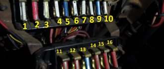
Fuse box location diagram for VAZ 2108, 2109, 21099
Let's talk about the location of all electrics in the circuits for the VAZ 2108, 2109, 21099. From the article you will learn where the fuses and relays are located, as well as what each of them is responsible for. In addition, we will give examples of troubleshooting electrical problems and replacing fuses with your own hands.
It must be said that the electrics in front-wheel drive VAZs 2108, 2109, 21099 are simple and unpretentious. Spare parts, components and the fuses themselves cost pennies, so don’t worry if they fail. Buying fuses for the VAZ “chisel” model is not difficult, they are available everywhere, and by the way, there is no threat of a shortage of these spare parts.
If a component of the car breaks down, for which the electrician is responsible, immediately figure out what the problem is. Using our recommendations, fuse diagrams and their meanings, you can easily replace fuses with your own hands. You can make the replacement without tools, following only the instructions.
The diagram below shows how to find the fuse box.
Immediately below the windshield is the fuse box.
The cover is removed by simultaneously pressing 2 latches as in the figure below.
How to open the fuse box
Take plastic tweezers, small pliers with narrow ends.
Use tongs or pliers to remove the fuse
Gently but firmly grasp the fuse with pliers and remove it with a vertical upward motion.
Removing the fuse from the block
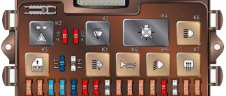
The photo below shows the appearance of the block without a cover.
Fuse box top view
The rear fog lamp fuse is separate from the unit and is located under the panel to the left of the driver.
Rear fog lamp fuse
Let's move on to the values of each of the fuses. In the table below we have covered the topic.
Removing and replacing the Lada Granta air filter with your own hands
Table of fuse values for VAZ 2108, 2109, 21099.
| Fuse, no. | Current strength, Ampere | Values |
| F9 | 7,5 | Right fog lamp |
| F8 | 7,5 | Left fog lamp |
| F1 | 10 | Relay, valve and activation of headlight cleaners |
| F7 | 30 | Headlight cleaner operation, washer pump, washer, rear window wiper and defroster, heater and radiator fan, glove box light |
| F16 | 15 | Windshield wipers, turn signals and tail lights, alternator, brake fluid level, oil pressure, parking brake, carburetor choke, coolant temperature, fuel level and voltmeter |
| F3 | 10 | Car interior lighting, rear lights |
| F6 | 30 | Window lifters |
| F10 | 7,5 | License plate lighting, engine compartment lighting, instrument lighting, side lights, cigarette lighter lighting |
| F5 | 20 | Klaxon |
| F11 | 7,5 | Side light of rear right lamp |
| F2 | 10 | Alarm |
| F4 | 10 | Relay, switching contacts and rear window heating element, cigarette lighter |
| F15 | 7,5 | High beam right headlight |
| F14 | 7,5 | Left high beam |
| F13 | 7,5 | Low beam left headlight |
| F12 | 7,5 | Low beam right headlight |
Old sample
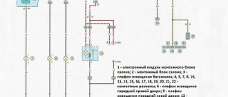
First of all, special attention should be paid to the electrical circuit. Below is an image of the old style fuse box diagram
The electrical circuit and pinout are responsible for the performance of many systems, ensuring their uninterrupted operation if necessary. For example, signals can be sent to window regulators.
It is also worth taking a closer look at the functions that the relay performs. They are summarized in a table.
| No. | Purpose |
| 1 | Organization of the operation of the component used to clean the dashboard. |
| 2 | Ensuring the protection of turn signal lights from possible damage and checking the functionality of the headlights. |
| 3 | Organization of rear window heating. |
| 4 | Organizing the supply of light to the low beam lamps and the operation of the wipers. |
Also, with the help of a relay, it is possible to organize the operation of the cooling system and stove during the cold season. This also ensures that the seats are heated. In addition, this is not a complete list of possible power supply functions that any VAZ 2108 car owner can or could use. For example, electric current can send brake lights.
Layout diagram, pinout
| Name / amperage (A) | Designations / what they are responsible for |
| F1 (10) | Reservation |
| F2 (10) | Turn signal indicators, hazard warning lights, hazard warning lights |
| F3 (10) | On the brake light, interior lighting of the VAZ 2109 car |
| F4 (20) | Heated rear window, plug, for cigarette lighter |
| F5 (20) | Sound signal |
| F6 (30) | Reserved |
| F7 (30) | Heater fan, windshield washer, radiator cooler activation relay, rear window heating, warning lamp, glove compartment lighting |
| F8 (7.5) | Reserved |
| F9 (7.5) | Reserved |
| F10 (7.5) | Left dimensions |
| F11 (7.5) | Right dimensions |
| F12 (7.5) | Low beam (right) |
| F13 (7.5) | Low beam (left) |
| F14 (7.5) | Left headlight DS |
| F15 (10) | Right headlight DS |
| F16 (10) | High beam indicator, fuel pump |
Designations and markings of the relay mounting block
| Number | What is he responsible for? |
| P1 | Cleaners (wipers) of front optics |
| P2 | Rear window washer |
| P3 | Turn signal lamp relay, light alarm |
| P4 | Wiper motor |
| P5 | Diagnostics of warning lamps on the tidy (high panel) |
| P6 | Surge protection |
| P7 | High beam lamp protection |
| P8 | Low beam lamp protection |
| P9 | Cooling fan |
| P10 | Klaxon |
| P11 | Reservation |
| P12 | Reservation |
The price of a new type power supply starts from 2000 rubles, individual melting elements from 100 rubles, a set from 350 – 450 rubles, depending on the manufacturer.
In Euroblocks, the fuse current was increased by 0.5 Amperes. Instead of the old 7.5 Amperes, 8.0 Amperes are installed. Remember this when choosing and purchasing consumables for repairs or replacement with a VAZ 2109 (8, 16 valves).
Signs of faulty fuses
- The module has changed color, black dots and carbon deposits are visible on the surface;
- An indicator on the instrument panel indicates a malfunction in the engine compartment;
- When the engine is running, the ignition is on, and the battery is charged, some mechanisms do not work or do not work correctly;
- In the interior of the car you can hear the smell of burning, melted in the area where the mounting block is located;
- The modules feel hot to the touch.
Marking 17.3722
Let's take a look at the electrical circuit of the old-style power supply unit, as well as the purpose of the fuses. As we said at the beginning of the article, a power supply with such a circuit can be found in a VAZ 2109, both equipped with an injection and a carburetor engine.
Old-style power supply circuit Old-style VAZ 2109 block
If you are the owner and your heater fuse or fuel pump fuse has failed, for example, then it would be useful for you to know the purpose of the unit’s parts.
Purpose of old-type power supply components
In addition, information about the purpose of the relay will be useful to you. It is presented below.
| Number | Purpose |
| 1 | Responsible for the functioning of the headlight cleaning elements. |
| 2 | This relay determines the functionality of the rear window washer motor. |
| 3 | This component protects against failure of the turn signal lamp lamps, as well as light signaling. |
| 4 | Protects the windshield wiper motor from damage. |
| 5 | Using these jumpers you can determine whether the lamp is working or not. |
| 6 | This component protects the rear window defroster mechanism from overvoltage. |
| 8 | High beam headlight bulbs. |
| 9 | Low beam headlight bulbs. |
| 11 | Without this device, the engine cooling fan will not be able to operate. If this device breaks down, there is a possibility of the motor overheating. |
| 12 | Responsible for the operation of the horn. |
Marking 2114-3722010-60
Now let's look at the electrical circuit and the purpose of the parts of the new block. As stated above, this scheme will be relevant for both injection and carburetor internal combustion engines.
Electrical diagram of a new type of power supply on the VAZ 2109 since 1998.
Below is a table explaining each part of the device.
Description of the purpose of the new type of power supply components
We will also consider the purpose of the relay.
| Number | What is he responsible for? |
| K1 | Without this component, the rear window washer motor cannot operate. |
| K2 | Responsible for the operation of turn signal lamps, as well as light signaling. |
| K3 | Responsible for the operation of the windshield wiper engine. |
| K4 | The purpose of the relay is to protect the brake lamps, as well as the dimensions of the vehicle. |
| K5 | This component ensures the functionality of the high beam lamps. |
| K6 | This part ensures the operation of the headlight washer device. |
| K7 | This relay protects against failure of the power window motor. Of course, this is true if power windows are installed in your car. |
| K8 | Klaxon. |
| K9 | Protects the cooling system fan from overvoltage. |
| K11 | Ensures the functionality of the rear window heating device. |
| K12 | Low beam lamps. |
Removal and replacement process
In practice, VAZ 2109 owners often encounter problems when the fuse for the cigarette lighter fails, the lamps on the instrument panel, the heater or the fuel pump do not work.
If the PP is to blame for the non-working condition of the electrical equipment, then you should replace it. In principle, the change process is no different.
The difference lies only in the power supply circuit and the different housing of the power supply itself.
For carburetor and injection engines
- First of all, you need to open the hood and disconnect the negative terminal from the battery. Remember that all repair work related to the power supply must be performed with the battery turned off.
- Find the power supply under the windshield near the driver's seat. It is protected by a plastic cover. Press the latches on its sides to remove the cover.
- Remove the cover and on the back you can see a wiring diagram that shows the location and purpose of each component.
If you need to replace a part responsible for the operation of the stove, cigarette lighter, gas pump or other equipment, then find it in the diagram or use our manual. After this, remove the PP by hand or using special tongs. If you are replacing a relay, remove it by rocking it up and down. - Replace the burnt part with a new one of the appropriate rating. A burnt-out PP can be identified by a broken fusible thread. Carry out the entire installation in reverse order. Connect the negative terminal of the battery.
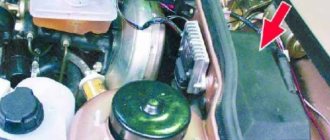
On the left side relative to the movement of the car, under the windshield you will find a black block in which all the PCBs and relays are installed. Remove the cover by pressing the latches on the side. Using pliers (BP marking 2114-3722010-60), remove the burnt part from the seat. In the case of the old marking block 17.3722, remove the burnt-out element by hand. The red arrow in the photo shows where the number is printed on the PCB body. When replacing, the nominal value must be observed. Install a new element in place of the burnt-out PP, observing the nominal value. Don't forget to close the power supply cover and connect the battery.
Video from Sergei Zukol “Reworking the VAZ 2109 power supply”
This video shows the process of converting a power supply from an old model to a new one.
Was this article helpful?This article was helpfulPlease share the information with your friends
Source: https://avtozam.com/vaz/2109/raspolozhenie-predohranitelej/
Welcome to VAZ.EE+ Extended Edition
Since May 2013, our portal has expanded the thematic sections of the forum for the exchange of experience: subforums Americans, Koreans, Germans, French, Japanese have been added, due to the increase in the fleets of our visitors. In addition to changing the style, our Chat, Mail, Entertainment and photo/video sections, Literature have become built-in and do not require separate registration. In addition, there are other useful and pleasant innovations that you can all familiarize yourself with when visiting the portal.
You can contact the administration with questions and suggestions in a special section of the forum or through the feedback form.
- literature Articles
- Library
entertainment
- Jokes
Jokes Miss Bikini forum
- Cars
Exchange of experience Operation About everything Forum and Web multimedia
- Gallery
Video Auto Wallpaper Photobase buy/sell
- Automobile
Auto parts miscellaneous Banners
- Help
- Search
- Users
- Reputation
- Forum home
- Experience exchange
- Electrical equipment
- print version
- Download/Print theme
- Display Modes
- Switch to: Tree-like
- Standard
- Switch to: Linear
How to remove and replace the block
Such an operation may be necessary if it is necessary to repair the power supply or replace it with a new unit. Even a novice driver can do this. You will need a 10mm wrench (it is best to use a socket or socket). Before removing the power supply, open the hood of the car's engine compartment.
Procedure for removing the power supply:
- Disconnect the terminals from the battery. This is necessary to prevent the possibility of a short circuit in electrical equipment.
- For ease of operation, remove the protective plastic top cover of the power supply unit.
- The block is secured to the body with two screws (they are removed with a wrench).
- Disconnect the connectors with wires. One of them is located in the engine compartment on the wide side of the block closer to the windshield. First, remove the rubber protective cover, and then, rocking it from side to side, disconnect the connector.
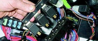
- The remaining connectors are located at the bottom of the power supply. To get to them, remove the two outer relays, painted black. After this, the power supply housing is lifted up and the remaining connectors are disconnected.
The unit is removed from the engine compartment for repair or replacement. Reinstalling it in place is carried out in the reverse order.
In this case, pay attention to the rubber gasket between the power supply and the car body. It must be intact, without cracks or tears, otherwise it must be replaced with a new one.
The gasket is needed to protect the power supply from moisture, which can cause a short circuit in the car's electrical circuit.
Watch the video of the AvtoMalina channel about removing the VAZ 2109 fuse box
The basic procedures for removing the mounting block of any model are the same. To remove the mounting block, do the following:
- Remove the negative battery terminal.
- Unscrew the two nuts on the sides of the block (it is located on the driver's side of the engine compartment above the vacuum brake booster).
- Lift the unit as far as possible and pull out all the connectors from the bottom.
- Install in reverse order. First insert all the connectors, then tighten the nuts.
How to disassemble and reassemble
Before disassembling the mounting block, print out a photo or diagram of the fuses and relays, and mark or write down where each relay is installed, because the parts description on the inside of the cover is not always helpful.
- Remove the cover. To do this, on the old model of the block, unfasten one latch from each side; on the new model, unfasten two latch from each block.
- Remove all relays and fuses. The new model has special tweezers that help pull out fuses; it is located next to the turn signal relay.
- After this, unscrew the screws that connect both halves of the body.
On most older model blocks, the screws are installed on top. Most new ones have bottom. But it also happens the other way around, because blocks are produced not only by AVTOVAZ. Use a thin flathead screwdriver to separate both halves of the housing. If you cannot disconnect, make sure that you have unscrewed all the screws and try inserting the screwdriver in a different place. Opening the case, remove the printed circuit board with the connectors installed on it. Reassemble in reverse order. First, install the circuit board onto the mountings of one half of the case, then slide the other half on and gently press them together until they are connected. If you cannot connect the case halves, disassemble them and make sure that the printed circuit board is in place, then reassemble. Then secure the body halves with self-tapping screws.
How to repair
Carefully inspect the traces of the printed circuit board. If you find dirt somewhere between the tracks, moisten it with nail polish remover and a brush. Make sure that the varnish does not dissolve the brush. After all dirt has been removed, thoroughly wipe the tracks with alcohol and dry with compressed air. Perform this operation on both sides of the PCB. Inspect all connectors.
If dirt or oxidation is found, replace them. If you do not have the necessary knowledge, tools or parts to do this, contact an auto electrician. Do not treat connectors with contact cleaning sprays; there is a high probability that some contacts will not be cleaned the first time. In addition, the spray will not help restore contact if the pressure plates (petals) are worn out or weakened. If the circuit board cannot be repaired and a new unit is expensive, buy and install a new circuit board. Before doing this, make sure that it is suitable for your unit by comparing the catalog number of your unit and the one for which the board is intended.
How to check heating?
To do this, you need to wrap the voltmeter probe in aluminum foil and press the foil with your finger and move it along the conductive threads. This way you can detect where the threads are broken.
Initially the voltmeter will show a voltage of 6V. If it displays 12 V, then in this place there is a break in the thread on the side between the connection point of the voltmeter and the heater side. If the voltage is below 0 V, then the conductive strip has a break on the side between the connection point of the volt meter and the heater side.
It is recommended to use an ohmmeter to measure the resistance of the conductive strip between the side terminal of the heater and the center of the strip. The section of the strip with the gap will have twice the resistance of the remaining strips.
You can repair a conductive strip using a conductive mass: glue mixed with metal shavings, a special material. You will also need electrical tape, solvent, and a brush. Use a solvent to clean the area of the glass where the conductive strip of the heater breaks. Electrical tape will be needed as a stencil. Apply conductive compound and remove adhesive tape. After a day, you can remove the excess.
Where are the fuses VAZ-2108 2109 21099
The relay and fuse block for the VAZ 2108-09-099 (carburetor, injector) is located under the hood, in the compartment in front of the windshield on the left side.
Fuse mounting block 2114-3722010-18
- K1-relay for turning on headlight cleaners;
- K2-relay-breaker for direction indicators and hazard warning lights;
- K3 - windshield wiper relay;
- K4-relay for monitoring the health of lamps;
- K5-power window relay;
- K6 - relay for turning on sound signals;
- K7-relay for turning on the electric heating of the rear window;
- K8-relay for high beam headlights;
- K9-relay for low beam headlights;
- F1-F16 - fuses
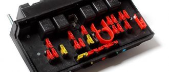
Fuse mounting block 2114-3722010-60
- K1 - Relay for turning on headlight cleaners
- K2 - Relay interrupter for direction indicators and hazard warning lights
- K3 - Windshield wiper relay
- K4 - Relay for monitoring the health of brake lamps and side lights
- K5 - Power window relay
- K6 - Horn relay
- K7 - Heated rear window relay
- K8 - Headlight high beam relay
- K9 - Relay for low beam headlights
- F1 - F16 - Fuses
- F1 - F20 - Spare fuses
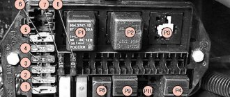
Fuse mounting block 17.3722
- 1 - relay for turning on headlight cleaners (K6)
- 2 - rear window washer time relay (K1)
- 3 - relay-breaker for direction indicators and hazard warning lights (K2)
- 4 - windshield wiper relay (KZ)
- 5 - contact jumpers in place of the lamp health monitoring relay
- 6 — relay for turning on the heated rear window (K10)
- 7 - spare fuse
- 8 - headlight high beam relay (K5)
- 9 - relay for low beam headlights (K11)
- 10 - fuse
- 11 — relay for switching on the electric motor of the engine cooling fan (K9)
- 12 - horn relay (K8)
Description of the mounting block fuses for VAZ 2109, 2108, 21099
F1-F16 - mounting block 2114-3722010-60, 2114-3722010-18.
Numbers from 1 to 16 - old-style mounting block 17.3722
| Fuse no. | Decoding |
| 1 (8 A) F9 (7.5 A) | Right fog lamp |
| 2 (8 A) F8 (7.5 A) | Left fog lamp |
| 3 (8 A) F1 (10 A) | Headlight cleaners (at the moment of switching on). Relay for turning on headlight cleaners (contacts). Headlight washer activation valve |
| 4 (16 A) F7 (30 A) | Headlight cleaners (in operating mode). Relay for turning on headlight cleaners (winding). Heater fan motor - heater fuse Window washer motor. Rear window wiper motor. Rear window washer timing relay. Valves for turning on the windshield and rear windows. Relay (winding) for turning on the electric fan of the engine cooling system. Relay (coil) for turning on the heated rear window. Rear window heating indicator lamp. Glove compartment lamp |
| 5 (8 A) F16 (15 A) | Direction indicators and relay-interrupter for direction indicators and hazard warning lights (in turn indication mode). Turn signal indicator lamp. Rear lights (reversing lamps). Gearmotor and windshield wiper activation relay. Generator excitation winding (when starting the engine). Brake fluid level warning lamp. Oil pressure warning lamp. Carburetor air damper warning lamp. Parking brake warning lamp. "STOP" light display lamp. Coolant temperature gauge. Fuel level indicator with reserve warning lamp. Voltmeter |
| 6 (8 A) F3 (10 A) | Rear lights (brake lamps). Interior lighting |
| 6 (8 A) F6 (30 A) | Power windows for front doors. Power window relay |
| 7 (8 A) F10 (7.5 A) | License plate lights. Engine compartment lamp. Instrument lighting lamps. Indicator lamp for external lighting. Heater lever illumination display. Cigarette lighter lamp |
| 8 (16 A) F5 (20 A) | The electric motor of the engine cooling system fan, and its activation relay (contacts). Sound signal and relay for its activation |
| 9 (8 A) F10 (7.5 A) | Left headlight (side light). Left rear light (side light) |
| 10 (8 A) F11 (7.5 A) | Right headlight (side marker). Right rear light (side light) |
| 11 (8 A) F2 (10 A) | Direction indicators and hazard warning relay-breaker (in hazard warning mode). Hazard warning lamp |
| 12 (16 A) F4 (20 A) | Rear window heating element. Relay (contacts) for turning on the heated rear window. Plug socket for portable lamp. Cigarette lighter |
| 13 (8 A) F15 (7.5 A) | Right headlight (high beam) |
| 14 (8 A) F14 (7.5) | Left headlight (high beam). Indicator lamp for high beam headlights |
| 15 (8 A) F13 (7.5 A) | Left headlight (low beam) |
| 16 (8 A) F12 (7.5 A) | Right headlight (low beam) |
Numbering of mounting block terminals 2114-3722010
| Connector | Contact | Wire color | Purpose |
| X1 (Ш1) | 1 | B | window lifters |
| 2 | G | ignition switch (cl. 15/2) | |
| 3 | GP | ignition switch (terminal 15) | |
| 4 | ZhG | heater motor switch | |
| 5 | R | ignition switch (cl. 30/1) | |
| 6 | KR | ignition switch (terminal 30) | |
| 7 | door lock | ||
| 8 | P | ignition switch (terminal 50) | |
| X2 (Ш2) | 1 | BG | rear window wiper switch |
| 2 | G | Turn signal switch (right) | |
| 3 | RP | brake light switch | |
| 4 | B | lamp continuity indicator | |
| 5 | IF | hazard warning switch | |
| 6 | GB | left front door | |
| 7 | ABOUT | rear fog light switch | |
| 8 | 34 | high beam warning lamp | |
| 9 | – | ||
| 10 | 4 | rear fog light switch | |
| 11 | sch | fuel reserve warning lamp | |
| 12 | IF | fuel level warning lamp | |
| 13 | Warhead | interior lamp | |
| 14 | KG | hand brake warning lamp | |
| 15 | hh | Turn signal switch (left) | |
| 16 | electric motor for headlight cleaner | ||
| 17 | – | ||
| X3 (Ш3) | 1 | and | speed sensor |
| 2 | emergency | hazard warning switch | |
| 3 | GP | direction indicator switch | |
| 4 | SB | oil level warning lamp | |
| 5 | H | weight | |
| 6 | RB | washer fluid level warning lamp | |
| 7 | RO | brake lining wear warning lamp | |
| 8 | 3 in | headlight switch | |
| 9 | ZhZ | windshield wiper switch | |
| 10 | PG | portable lamp connection socket | |
| 11 | ignition switch (terminal 15) | ||
| 12 | RF | rear window washer switch | |
| 13 | |||
| 14 | and | fog light warning lamp | |
| 15 | |||
| 16 | SG | oil pressure indicator | |
| 17 | |||
| 18 | R | wiper switch | |
| 19 | CO | wiper switch | |
| 20 | WITH | wiper switch | |
| 21 | ABOUT | rear fog light switch | |
| X4 (Ш4) | 1 | Salary | On and indicator lamp for heated rear window |
| 2 | GB | headlight switch (high beam) | |
| 3 | ABOUT | wiper | |
| 4 | Warhead | outdoor lighting switch | |
| 5 | TO | Instrument lighting rheostat | |
| 6 | R | battery | |
| 7 | BW | windshield wiper and washer switch | |
| 8 | ABOUT | block Ш4 of the mounting block terminal 3 | |
| 9 | midrange | horn switch | |
| 10 | BP | brake light switch | |
| 11 | R | battery | |
| 12 | JV | headlight switch (low beam) | |
| 13 | warning light | ||
| 14 | – | ||
| 15 | – | ||
| 16 | RG | brake fluid level warning lamp | |
| 17 | ZB | coolant temperature gauge | |
| 18 | KB | battery charge indicator lamp | |
| 19 | ZhCh | fog light switch | |
| 20 | RZ | coolant level warning lamp | |
| 21 | AND | tachometer | |
| X5 (W5) | 1 | 3 | high beam (right) |
| 2 | 3H | high beam (left) | |
| 3 | midrange | low beam (left) | |
| 4 | P | starter (cl. 50) | |
| 5 | PB | electric radiator cooling fan | |
| 6 | WITH | low beam (right) | |
| X6 (Ш6) | 1 | – | |
| 2 | 3 | reverse light switch | |
| 3 | MS | Turn signal (left front) | |
| 4 | – | ||
| 5 | – | ||
| 6 | – | ||
| 7 | – | ||
| 8 | ZhCh | side light (right front) | |
| 9 | Warhead | electric fan thermostat | |
| 10 | ZhCh | side light (left front) | |
| 11 | G | Turn signal (right front) | |
| 12 | reverse light switch | ||
| 13 | RG | brake fluid level sensor | |
| X7 (W7) | 1 | – | |
| 2 | ZhG | electric motor for headlight cleaner | |
| 3 | B | electric motor for headlight cleaner | |
| 4 | – | ||
| 5 | SB | oil level sensor | |
| 6 | midrange | sound signals | |
| 7 | WITH | speed sensor | |
| 8 | ZB | coolant temperature sensor | |
| 9 | KB | generator (cl. 61) | |
| 10 | R | windshield washer pump | |
| 11 | Warhead | engine compartment lamp switch | |
| 12 | RB | washer fluid level sensor | |
| 13 | RF | brake linings | |
| 14 | – | ||
| 15 | KP | tachometer | |
| 16 | RZ | coolant level sensor | |
| 17 | reinforced concrete | fog light relay | |
| X8 (W8) | 1 | ZhP | fog light relay |
| 2 | ZhCh | fog lamp (left) | |
| 3 | AND | fog lamp (right) | |
| 4 | GP | ignition coil | |
| 5 | R | generator (cl. 30) | |
| 6 | R | generator (cl. 30) | |
| 7 | – | ||
| S | RF | fog light relay | |
| X9 (W9) | 1 | RF | electric motor rear window wiper |
| 2 | G | Turn signal (right rear) | |
| 3 | BG | electric motor rear window wiper | |
| 4 | VERY | rear fog lights | |
| 5 | midrange | back door | |
| 6 | IF | front right door | |
| 7 | Warhead | interior lamp | |
| 8 | KG | handbrake sensor | |
| 9 | Warhead | open door alarm buttons | |
| 10 | rear window heating elements | ||
| 11 | WITH | license plate light | |
| 12 | GB | front left door | |
| 13 | B | interior lamp | |
| 14 | P | brake lights | |
| 15 | AND | side light (right rear) | |
| 16 | 3 | reversing light | |
| 17 | ZhCh | side light (left rear) | |
| 18 | ZhG | rear window cleaner | |
| 19 | rear window heating elements | ||
| X11 (W11) | 1 | AND | pump |
| 2 | RF | rear window washer valve | |
| 3 | – | ||
| 4 | AND | pump | |
| 5 | Warhead | engine compartment lamp | |
| 6 | – | ||
| 7 | – | ||
| 8 | CC | engine compartment lamp | |
| 9 | B | electric windshield wiper motor | |
| 10 | windshield wiper motor | ||
| 11 | – | ||
| 12 | CO | emergency oil pressure sensor | |
| 13 | – | ||
| 14 | R | windshield washer valve | |
| 15 | CO | electric wiper motor | |
| 16 | WITH | electric windshield wiper motor | |
| 17 | reinforced concrete | electric windshield wiper motor | |
| 18 | – | ||
| 19 | – |
service features with photos and video recommendations The auto electrician himself
Owners of Samaras from the first years of production often complain about burnt contacts and faulty electronics. The reason for this is most often low-quality components, which the VAZ 21093 electrical wiring abounds in sufficient quantities. And when the first symptoms appear, you should immediately begin repairing faulty components, since the safety of road users depends on this.
Wiring should be looked after from the very first days
Mounting block
Of particular concern is the mounting block, which is located in the “wet” area under the hood - the drainage hole often becomes clogged, and moist air gets inside, oxidizing the contacts. The VAZ 21099 also has similar design flaws.
Due to the design feature, the mounting block is exposed to dirt and moisture
Symptoms
Original wiring diagram for VAZ 21093 carburetor
The car signals to the owner that not everything is in order with the contacts in the most unusual way:
- When the fan is turned on, the engine begins to stall;
- The power unit behaves similarly when the high beam headlights are turned on;
- When you turn on the starter, a smell of burnt plastic appears in the cabin;
- Similarly, when turning on a heating stove, etc. while moving.
Such “finds” are not uncommon at Samara.
If one of these symptoms appears to you, you need to immediately correct the situation with your own hands before it gets out of control.
Note! The fact is that the wiring of the VAZ 21093 to the injector is characterized by quite high loads, and any unstable connection in the circuit can turn into disaster, the price of which is the cost of the car and your health
Video
Watch a video from the Mechanics channel about removing the VAZ 2109 fuse box
Do you have any questions? Specialists and readers of the AUTODVIG website will help you ask a question
Was this article helpful?
Thank you for your opinion!
The article was useful. Please share the information with your friends.
Yes (100.00%)
No
X
Please write what is wrong and leave recommendations on the article
Cancel reply
Rate this article: ( 3 votes, average: 5.00 out of 5)
Discuss the article: