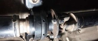
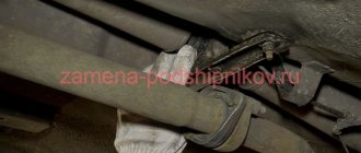
Cardan transmission with unequal velocity joint
This type of transmission can be found on rear-wheel drive or all-wheel drive vehicles.
The structure of such a transmission is as follows: joints of unequal angular velocities are located on the cardan shafts. There are connecting elements at the ends of the transmission. If necessary, a connecting support is used. The hinge combines a pair of forks, a cross and locking devices. The fork eyes have needle bearings in which the crosspiece rotates.
Copy-paste:
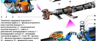
On the carefully processed fingers of the crosspiece 3, steel glasses 13 with needle bearings 12 are installed. The bearing needles at the inner end rest on the support washer 11. The glass is sealed on the crosspiece with a rubber seal 10 installed in a metal housing 9, which is put on the crosspiece. The crosspiece with glasses is secured in the fork ears 2 and 4 with retaining rings or plates 6 with screws. The crosspiece bearings are lubricated through the central oiler 7, from which the oil reaches the bearings through channels in the crosspiece. To eliminate excess oil pressure, a housing with a safety valve 8 is threaded into the crosspiece.
Bearings cannot be repaired or serviced. Oil is poured into them during installation.
The peculiarity of the hinge is that it transmits unequal torque. The additional shaft periodically overtakes and lags behind the main shaft. To compensate for this deficiency in the transmission, several joints are used. The forks of opposite hinges are located in the same plane.
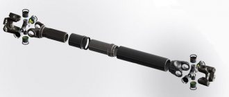
Depending on the distance over which torque must be transmitted, one or two shafts are used in the cardan transmission. When the number of shafts is equal to two, one of them is called intermediate, the second is called rear. To fix the shafts, an intermediate support is installed, attached to the car body.
The cardan drive is connected to other elements of the car using flanges, couplings and other connecting elements.
It is safe to say that unequal velocity joints have low reliability and a relatively short service life. In modern conditions, cardan drives with constant velocity joints are used.
Designs of universal joints
An asynchronous rigid cardan joint (Fig. 8, a) consists of two steel forks 6 and 1O fixedly mounted on the drive and driven shafts and a crosspiece 8 that pivotally connects them. The crosspiece 8 is movably connected to the fork using a needle bearing. The bearing housing 3 (Fig. 8, b) is installed in the hole of the eye 12 of the fork with tension and is secured against axial movement and rotation using the cover 4. The needles 15 of the bearing rest on the cylindrical ground surfaces of the 13 tenons of the fork. Between the end surfaces of the housing 3 and the fork studs 13, dirt deflectors 16 and oil seals 5 are installed, protecting the bearing surfaces from dirt and preventing lubricant leakage. The oil seal is installed in a thin stamped cage 17 and pressed into the bearing housing. In modern designs of spider bearings, lubricant can be added during assembly or supplied during servicing of the cardan drive.
Rice. 8. Design of asynchronous rigid gimbal joint
The housing is fixed in the axial direction using cover 4 (Fig. 8, b) or locking ring 14 (Fig. 8, c). Needle bearings make it possible to reduce the size of the universal joint and increase the number of rolling elements that transmit torque. At small angles between the shafts, rolling the needles over the surface of the tenon is difficult; as a result, the bearing needles can be pressed into the surface of the tenons (the phenomenon of “brinelling”) and the hinge fails. Therefore, in cardan transmissions, a small (1... 2)° difference is provided between the angles of the shafts, ensuring the movement of the needles.
Synchronous rigid cardan joints are quite complex structurally, technologically and more expensive. Therefore, they are mainly used in drives of steered wheels or to reduce vibration of cardan drives. Cardan joints of equal angular velocities are divided by design into ball joints with dividing grooves, ball joints with a dividing lever, cam joints, disk joints and double simple rigid joints.
A simple double cardan joint (Fig. 9) consists of two simple cardan joints mounted on the drive shaft 1 and driven shaft 2 and a short shaft 3 (double yoke) between them. The centers of the spherical surfaces of the shaft 1 and the spherical divider 5, movably mounted at the end 4 of the shaft 2, are located on the axis of the shafts, in the middle of the distance between the axes of the crosses 7 and 8. When one of the shafts is angularly displaced, the center of the spherical hole 6, rigidly connected to the shaft 1 , moves along a circular arc equal to half the distance between the axes of vertically located spikes.
The spherical divider 5 rotates in the plane of the shaft axes, and the movable end 4 of the shaft 2 is displaced relative to the divider and the center of the divider hinge is shifted towards the drive shaft. The protective cover 9 hermetically closes the cavity of the divider 5. For hinges of unequal angular velocities, united by a double cross, the equality of the angular velocities of the shafts must be ensured by the dividing lever. However, such equality is possible only if the angles α1=α2 are equal, Fig. 9.
Rice. 9. Scheme of a double universal joint
In this design, this requirement is not met, since when the shaft is tilted, the arm associated with the left shaft remains constant, and the arm associated with the other shaft increases. Therefore, in a double joint with a dividing lever, synchronous rotation of the connected shafts can be ensured only with some approximation. Despite the existing kinematic discrepancy, the divider ensures rotation of the shafts at approximately the same angles, and the angular velocities of the shafts differ slightly.
The cam joint (Fig. 10) consists of two forks 1 and 6 connected to the drive and driven shafts, and two shaped cams 3 and 4.
Rice. 10. Design of the cam joint: a - diagram; 6 - details
The angular movement of parts is carried out by sliding of the mating cylindrical and centering flat surfaces of the forks and cams. The cylindrical surfaces 7 of the forks 1 and 6 cover the cylindrical surfaces of the cams 8, which are centered along the plane of the forks by rectangular cutouts 9. The shaped protrusion 2 of the cam 3 (disk segment) fits into the shaped slot 5 (of the same shape) of the cam 4, is centered along the side surfaces of the slot and can rotate in the slot. The design of the cam joint is similar to a simple double joint, with the shaped cams acting as a double yoke.
Hinges are used in drives of steered wheels of drive axles of trucks with a large gross weight. Placed in the axle housing, they are protected from external factors and are well lubricated, and the relatively large contact surface of the parts reduces the load and ensures acceptable durability. This type of universal joint provides torque transmission at angles up to 40°.
The cam-disk joint (Fig. 11) consists of driving 1 and driven 4 forks, rigidly mounted on the cardan transmission shafts, cams 2 and 3 and disk 5.
Rice. 11. Cam-disc joint design
The inner cylindrical surfaces 6 of the forks cover the outer cylindrical surfaces of 7 cams, the disk 5 is inserted into the slots 8 of the cams, shaped like a disk segment. When the angled shafts rotate, the forks rotate relative to the cams and, together with the cams, relative to the disc. The cams and disc act as a double fork. With small deviations in the alignment of the shafts and the symmetry of the location of the hinge parts, approximately equality of the angular velocities of the shafts is ensured. The design of the hinge is quite simple and technologically advanced. Used in drives of steered wheels of trucks. Provides torque transmission at angles up to 50°.
A ball joint with a centering ball (Fig. 12) consists of a driving 2 and a driven 3 forks, rigidly connected to shafts 1 and 4 Fig. 12, a. On the inner surfaces of the forks there are four dividing grooves 5 of a special profile, in which balls 6 are installed. The centering ball 7 is installed in the spherical recesses of the forks (Fig. 12, a, c), coaxial with shafts 1 and 4.
Rice. 12. Ball joint with centering ball
The center lines of the profiled grooves are circles with identical radii R, (Fig. 12, 6) whose centers are located at the same distance “a” from the center of the hinge. When the forks rotate, the middle lines of the grooves form two spherical surfaces with a radius R, the intersection line of which is a circle located in the bisector plane A-A of the angle between the shafts. In this case, the centers of the balls located on the middle line of the grooves, due to the symmetrical arrangement of the grooves in both forks, are also always in the bisector plane.
Ball 7 ensures the centering of the shafts and ensures a backlash-free connection of the forks. The transmission of torque using balls leads to significant contact stresses on the surface of the mating parts, especially since the design of the hinge provides for the transmission of torque in each direction using two, rather than all four balls. If the shafts are misaligned, the balls not only roll along the grooves, but also slide along their surfaces. In combination with high contact stresses, this reduces the durability of the hinges.
Ball joints of this type are mainly used in drive steering axles of trucks and cars with switchable drive. The hinge body connecting the steering knuckle to the drive axle casing experiences large axial loads, which limits the possibility of their use. The hinges provide torque transmission at angles between the shafts up to 30°.
A ball gear with a dividing lever (Fig. 13, 14) consists of a drive sprocket 3 and a spherical housing 1 mounted on the driven shaft, a separator 4, a dividing lever 7 with a spring 6 fixed inside the housing 1, a guide cup 5 and six balls 2.
Rice. 13. Ball joint parts with index lever
On the inner surface of the housing 1 and the outer surface of the sprocket 3 there are six grooves 9 and 10 each with toroidal surfaces symmetrical with respect to the plane passing through the axes of the shafts. There are balls 2 in the grooves, their relative position is set by the separator 4 and the guide cup 5. The separating lever 7 is fixed in the guide cup using hinge 9 (Fig. 14). The spherical surface 10 of the index lever is installed in the hole of the hinge housing 1, and the spherical surface 8 is installed in the spherical bushing 11, pressed into the hole of the sprocket Z. The lever is pressed by a spring 6, which ensures a backlash-free connection of the index lever with the sprocket.
Rice. 14. Ball joint with a dividing lever: a - diagram; 6 - design
When the angle between the shafts changes, the dividing lever 7 moves the guide cup 5 and with it the separator 3, so that the centers of the balls are located in the plane dividing this angle between the shafts in half. The torque in the joint is transmitted through all the balls, so universal joints of this type are highly durable and operate at angles between the shafts up to 35... 38°.
A ball joint with an eccentric arrangement of grooves (Fig. 15) consists of a driven part - housing 1, a drive sprocket 4, rigidly fixed to the shaft 5, and balls 2 installed in the separator 3. The hinge is covered with a rubber corrugated cover 6. Toroidal surfaces of the grooves of the housing 1 , the stars 4 and the centers of the balls 2 form eccentric spherical surfaces. The center of the sphere of the body 1 - 01 and the center of the sphere of the sprocket 3 - 03 with radius R3 are shifted relative to the center of the sphere of ball centers - O by a distance “a” (Fig. 15, b). If an angle appears between the shafts, the distance between the surfaces of the housing spheres and the sprocket changes. For example, when shaft 5 is rotated clockwise, the upper ball, under the action of the normal force component at the contact points, is pushed out of the gap between the housing and the sprocket, which decreases in height, and the lower ball (and other balls) due to the separator is shifted towards increasing this gap.
Rice. 15. Ball joint with eccentric arrangement of grooves: a - design; b - diagram
The operation of the hinge is characterized by less precise kinematics than the operation of a ball joint with a dividing lever, but the simplicity of the design, reliability and small dimensions have ensured the widespread use of the hinge in drives of steered drive wheels.
Cardan transmission with constant velocity joint
This type of transmission is widely used in front-wheel drive vehicles. It connects the differential and the drive wheel hub.
The transmission has two hinges - internal and external, connected by a shaft. CV joints are often used in rear-wheel drive cars and all-wheel drive cars. The fact is that constant velocity joints are more modern and practical, moreover, the noise level from them is much lower than from the CV joint.
The most common existing one is the ball-type constant velocity joint. The CV joint transmits torque from the drive shaft to the driven shaft. The angular speed of torque transmission is constant. It does not depend on the angle of inclination of the shafts.
The CV joint, or as it is popularly called a “grenade,” is a spherical body in which the clip is located. Balls rotate between them. They move along special grooves.
As a result, torque is uniformly transmitted from the drive shaft to the driven shaft under conditions of angle change. The separator holds the balls in the desired position. The “grenade” is protected from the influence of the external environment by a “boot” - a protective casing.
A prerequisite for a long service life of CV joints is the presence of lubricant in them. And the presence of lubricant, in turn, is ensured by the tightness of the hinge itself.
Separately, it is worth mentioning the safety of CV joints. If you hear a crackling or noise in the grenade, it needs to be changed immediately. Operating a car with a faulty CV joint is extremely dangerous. Simply put, the wheel may fall off. The reason why the driveshaft becomes unusable is most often the wrong choice of speed and poor road surface.
Cardan classification
Several types of driveshafts are used in the design of modern cars. They may differ not only from the manufacturer, but also from the type of car. Some identical models may have different types of gears.
Depending on the design, cardan drives can be:
- Single-shaft - a more powerful type, often installed on all-wheel drive or rear-wheel drive vehicles. This mechanism allows you to transfer torque to the wheels as quickly as possible.
- Multi-shaft is a more complex, but fragile mechanism that is present on most passenger front-wheel drive cars. In addition to the main shaft, an intermediate shaft is added (where the bearing is needed).
Operation of a multi-shaft cardan transmission
Based on the number of shaft supports, there are the following types:
- Double-bearing - do not have an outboard bearing, mounted on trucks or four-wheel drive vehicles.
- Three-bearing - have one bearing that connects the intermediate shaft and the main one. Applicable to most cars.
- Four-bearing - have several intermediate shafts connected by two bearings. A rare variety, installed on some Lexus and Chrysler jeeps.
Based on design features, the following models can be distinguished:
- With an NUS (unequal angular velocity) joint - a standard design installed on most cars with rear-wheel drive.
- CV joint is a modern cardan transmission that maintains equal angular speeds.
- Elastic semi-cardan joints.
- Rigid semi-cardan joints.
Most modern front-wheel drive cars are equipped with a CV joint type driveshaft. It is more comfortable and less subject to vibration, which is important for passenger cars. However, such a system is more complex, it is not cheap to maintain and can easily break if not properly maintained.
Main malfunctions and their symptoms
The most durable mechanism in the design is the shaft itself. It is cast from a strong alloy that can withstand extreme loads. Therefore, you need to try hard to damage it. As a rule, these are mechanical damage due to an accident.
In general, the main faults can be divided into several types:
- Vibration – when starting or moving, strong or weak vibrations may occur. This is the first sign of damage to the spider bearings. Also, the problem may indicate improper shaft balancing; this happens after mechanical damage.
- Knocking – a characteristic knocking sound when moving from a standstill will mean that the fastening bolts or splines have worn out. In this case, it is best to immediately contact a service station to check the integrity of the connection.
- Oil leak - you can find small oil droplets in the locations of bearings and seals.
- Creaks - they can appear when you press the gas pedal. In most cases, squeaks can be associated with faulty hinges. With the appearance of corrosion, the crosspiece may jam, which leads to bearing damage.
- Faulty moving bearing - the problem can be identified by a characteristic rustling sound in the area of the moving part of the shaft. During normal operation, the mechanism should not make any sounds, all movements should be smooth. If you hear a rustling noise, the bearing is most likely failing. The problem can only be solved by completely replacing the faulty part.
In rare cases where mechanical damage to the main shaft occurs, severe vibration can be generated due to its incorrect geometry. Some craftsmen recommend manually correcting the geometry of the pipe, but this is the wrong decision and can lead to rapid wear of the entire structure. The best solution would be to completely replace the damaged elements.
Operating principle of HF
The principle of operation of the cardan transmission is the ability to transport torque when the position of the “cardan” in space changes. This principle is implemented through two mechanisms:
- Sliding fork of the cardan shaft;
- Cross joint.
A sliding fork is necessary to slightly increase the length of the mechanism when driving on uneven roads. Due to the long spline connection, the supply of torque does not stop when the suspension, together with the rear axle, moves up or down.
The hinge, in turn, ensures rotation of the wheels when the bending angle of the CV changes. It is believed that the mechanism is capable of working productively at angles of no more than 20°. Then its active wear begins.
Appendix b (for reference). calculation of cardan shaft imbalance
Appendix B (for reference)
B.1 The imbalance of the cardan shaft depends on its mass and the clearances in the hinges and the mechanism for changing the length.
B.2 Unbalance D, g cm, in the section of the cardan transmission support is calculated using the formulas: - for a shaft without a mechanism for changing length
(B.1)
— for a shaft with a mechanism for changing the length
(B.2) where m is the mass of the cardan shaft per support, g; e is the total displacement of the shaft axis due to the axial clearances in the hinge between the ends of the crosspiece and the bottoms of the bearings and the radial clearance in the connection “crosspiece axle - crosspiece bearing”, cm; e is the displacement of the shaft axis due to gaps in the mechanism for changing the length, cm. Mass m is determined by weighing on scales placed under each support of a horizontal shaft. The total displacement of the shaft axis e, cm, is calculated using formula (B.3)
where H is the axial clearance in the hinge between the ends of the cross and the bottoms of the bearings, cm;
D — internal diameter in the bearing along the needles, cm; D is the diameter of the crosspiece axle, cm. The displacement of the shaft axis e, cm, for a movable spline joint centered along the outer or inner diameter e is calculated using formula (B.4) where D is the diameter of the spline hole in the sleeve, cm; D - diameter of the spline shaft, see Note - For a cardan shaft without a mechanism for changing the length, e=0. The minimum or maximum imbalance D is calculated taking into account the tolerance range of the mating elements of the propeller shaft.
Frequent malfunctions and their elimination
All malfunctions can be divided according to emerging signs of failure:
- Vibration when moving - the bearings of the cross or the sliding sleeve are worn out, the balancing of the shaft is disrupted;
- Knocks when starting - the sliding joint splines are worn out, the fastening bolts are loose;
- Oil leakage from the bearings means wear of the seals.
To eliminate the problems described above, the “cardans” are dismantled and defective, and faulty parts are replaced. If there is an imbalance, the shaft must be balanced under dynamic conditions.
Prospects for the development of a cardan transmission system
The classic ShNUS has some technological disadvantages. The rotation speed of its shafts changes during movement. In this case, the driven shaft can accelerate and decelerate at a stable speed of the drive shaft. This leads to accelerated wear of the mechanism and also creates excess load on the rear axle. Also, the operation of the hinge is accompanied by vibration.
The purpose of the cardan drive can be performed by a shaft equipped with CV joints (front and rear). Similar systems are already used on some SUVs today. Also, the cardan transmission of the VAZ-2107 and other “classics” can be equipped with a CV joint. Repair kits are available for sale.
The use of a constant velocity joint eliminates the disadvantages inherent in the classic cross. The shaft rotation speed is leveled out, vibration disappears, the HF does not require balancing after repair, and the torque transmission angle increases to 17°.
Types of cardan drives
In the modern automotive industry, the following types of cardan transmissions can be used:
- Equipped with a unequal velocity joint (classic car driveline);
- Equipped with CV joints (constant velocity joints);
- Equipped with semi-cardan elastic joints;
- Equipped with rigid semi-cardan joints.
The system with the NUS hinge is considered classic. There are forks, crosspieces, and needle bearings. Suitable for most rear wheel drive vehicles.
Modern SUVs often use a system equipped with CV joints. Such devices provide more comfortable driving conditions, almost completely eliminating vibrations.
Elastic hinges are a rubber coupling capable of transmitting torque at bends of no more than 8°. The rubber is quite soft, so a shaft with a similar structure ensures a smooth start of movement and the absence of sudden dynamic loads. In addition, flexible connections require no maintenance. The rigid semi-cardan joint has a complex technical device and transmits torque due to gaps in the spline connection. Due to the complexity of manufacturing, technical shortcomings and rapid wear, it is not used in the automotive industry.
Cardan transmission - purpose, types of gears, design and operation
As the car begins to move, it forces all its components and assemblies to move, including its transmission. Since it is in constant motion, the relative location of its individual parts may change accordingly.
Uneven road surfaces cause vibration of the drive axles connected by the suspension. The frame and body of the car also undergo some movements as a result of the influence of external factors. Accordingly, they can shift relative to each other and the axis of the shafts of the units that transmit torque from the car engine to the drive wheels.
This system of units is called a cardan transmission and is designed to balance the oscillatory movements of the car’s mechanisms for the smooth transmission of torque.
Depending on the vehicle, the cardan transmission can connect the following mechanisms:
- gearbox and transfer case;
- gearbox and final drive of the drive axle;
- main gears of the rear and middle driving axles;
- axle shafts and front drive wheels;
- main gear and drive wheels.
The structure of cardan drives in different cars is the same, the only differences are in the size of the units or in the shape of individual elements.
Cardan transmission design
The cardan transmission consists of the following elements:
- cardan joints;
- main and intermediate shafts;
- intermediate support with bearing;
- elastic coupling;
- connecting mechanisms.
Cardan transmission diagram, GAZ-3302 Gazelle car: 1 - shank of the sliding fork; 2 — sliding fork mud deflector; 3 — sliding fork; 4 — intermediate cardan shaft fork; 5 — intermediate cardan shaft; 6 — mud deflector; 7 — intermediate support; 8 — protective ring; 9 — intermediate support bearing; 10 — protective ring; 11 — splined fork; 12 - U-shaped plate; 13 — lock washer; 14 — crosspiece; 15 — rear propeller shaft fork; 16 — rear propeller shaft; 17 — flange of the main gear drive gear; 18 — rear universal joint; 19 — needle bearing; 20 — retaining ring; 21 - bolt; 22 - sealing ring.
So, let's look at the cardan transmission device
The elastic coupling in this design absorbs sudden jerks and vibration movements.
Diagram of an elastic coupling: 1 - elastic coupling; 2 — flange of the intermediate shaft of the gearbox; 3 — mud reflector; 4 — intermediate shaft of the gearbox; 5 - nut; 6 — centering ring seal; 7 — centering ring; 8 — elastic coupling liners; 9 - bolt; 10 - plug; 11 — front propeller shaft flange; 12 — cuff; 13 — splined end of the front propeller shaft.
Using two flanges, the coupling connects the gearbox and the front driveshaft. These two mechanisms are combined using a centering ring on the gearbox shaft and a centering sleeve, which is located in the driveshaft flange.
note
Cardan shafts are made of steel pipe. The front shaft is equipped with splined ends, and the rear shaft is equipped with universal joint forks.
The intermediate support is a ball bearing that is mounted in a bracket inside a rubber insulating pad.
The cardan joint consists of two forks connected to each other by a cross. The forks themselves are mounted on cardan shafts. On the hollow spikes of the cross there are needle bearings with o-rings.
Types of driveshafts
The main role in the cardan drive is played by the cardan joint, depending on the design of which the following types of cardan drives are distinguished:
- transmission with constant velocity joint;
- transmission with unequal velocity joint;
- transmission with a semi-universal elastic joint;
- transmission with a semi-cardan rigid joint.
By the number of shafts, cardan transmissions can be: single-shaft, double-shaft and multi-shaft, and by the number of hinges - single-joint, double-joint and multi-joint.
Operation of cardan gears
A universal joint drive with a constant velocity joint is typically used in front-wheel drive vehicles to connect the transmission to the drive wheels. This mechanism consists of two hinges (external and internal), which are connected by a drive shaft.
Diagram of a constant velocity joint (CV joint): 1 - clamp; 2 - axle shaft; 3 — dirt-proof cover (“boot”); 4 - clamp; 5 - separator; 6 — clip; 7 — semi-minor axis; 8 — hinge body; 9 — retaining ring; 10 - ball; 11 - conical ring; 12 - spring washer.
The constant velocity joint (CV joint) has a spherical body with a cage inside. There are grooves in the holder and body along which metal balls move. The presented design allows for uniform transmission of torque, even despite the changing angle of inclination of the mechanisms.
A cardan transmission with a joint of unequal angular velocities, depending on the distance over which the torque must be transmitted, has one or two cardan shafts. If two shafts are used, the first shaft is called the intermediate shaft, and the second is called the rear propeller shaft. The shafts are connected using an intermediate support, which is attached to the car body.
The unequal velocity joint consists of two forks located at an angle of 90 degrees to each other, a cross and connecting elements (bolts, couplings, flanges). The bearings in which the crosspiece rotates are inserted into special holes in the forks.
The presented cardan transmission differs in that during operation the torque moves unevenly, that is, in one cycle the driven shaft lags behind twice and advances the drive shaft twice, so at least two hinges are used here - one at each end of the shaft.
A cardan transmission with a semi-universal elastic joint ensures the movement of torque between two shafts located at a slight angle relative to each other.
Operation and possible malfunctions of the cardan transmission
Careful operation of the vehicle allows the driveshaft joints and ball joints of the front shafts to maintain their functionality for a long time, at least up to 100 thousand runs.
As for pipes, if there are no mechanical damages, they can be used for many years without replacement, otherwise the bent mechanism should simply be replaced with a new one.
You should pay attention to the condition of the hinge covers and replace them if they are damaged in any way, thereby protecting the hinges.
Important
A reduction in the performance of the joints can be caused by sudden acceleration, slipping in mud, incorrect choice of speeds, and long trips on snowy and dirt roads with deep ruts.
You can find out about a driveline transmission malfunction by the appearance of extraneous sounds or jerking of the car when driving. There are several reasons for the loss of performance of the cardan drive, and among them are the following:
- wear of cardan joints;
- deformation of cardan shafts;
- damage or wear of seals;
- damage to the protective cover of the hinge;
- bearing wear;
- weakening of connecting mechanisms.
These faults are very easy to fix by replacing damaged parts or tightening fasteners.
Chapter 6. Driveshafts (page 1)
Chapter 6.
cardan transmissions
1. Purpose of cardan drives
Transmission of torque when the shaft axes do not coincide and their relative position changes can be provided by cardan joints
.
The shafts connecting the universal joints are called driveshafts
.
A mechanism consisting of one or more cardan shafts and cardan joints and designed to transmit torque between units whose axes do not coincide and can change their position is called cardan transmission
. To compensate for changes in the distance between the transmission units and the cardan drive, axially movable splined couplings can be used.
The following requirements apply to cardan transmissions:
— transmission of torque without creating additional loads in the transmission (bending, twisting, vibration, axial);
— the ability to transmit torque while ensuring equality of angular velocities of the drive and driven shafts, regardless of the angle between the connected shafts;
— high efficiency;
— noiselessness.
On long-wheelbase vehicles, the cardan transmission often consists of two shafts: an intermediate and a main shaft (front or rear). This is necessary in cases where the use of a long shaft can lead to dangerous lateral vibrations as a result of the coincidence of its critical angular velocity with the operational one. A short shaft has a higher critical frequency. The intermediate shaft is mounted on an intermediate support.
If the intermediate shaft connects the driven shaft of the gearbox with the main driveshaft (VAZ, ZIL cars), then the intermediate support must have some elasticity. This is necessary for the reason that the car’s power unit (engine, clutch, gearbox), mounted on elastic cushions, has some freedom in both vertical and horizontal planes. For this reason, the intermediate support bearing housing is installed in a bracket with a rubber ring 1, and the bracket is mounted on the frame cross member (Fig. 1 a).
Some cars use intermediate supports with bearings rigidly installed in the body, but in this case the body itself can swing on axles that are connected to a bracket mounted on the frame cross member.
On three-axle vehicles that have an autonomous cardan drive to the intermediate and rear axles, a rigid support is usually installed on the intermediate shaft (Fig. 1- b
).
Fig.1. Intermediate supports for the cardan shaft:
a – elastic; b – hard.
Cardan joints of unequal angular velocities (asynchronous), having two fixed swing axes, are used in a cardan transmission when the driven shaft is tilted at an angle of no more than 20°.
Some variants of vehicle transmissions with different combinations of driveshaft arrangements of unequal angular velocities are shown in Fig. 2.
Universal joints
differ from simple ones in that in them axial compensation is carried out in the hinge mechanism itself without the use of an additional spline connection (coupling).
Universal joints of equal angular velocities
(synchronous) are used in the drive of driving steered wheels (Fig. 1-
a
and 1-
b
); The angle of inclination of the driven shaft, depending on the design of the hinge, can reach 45°. Some designs of synchronous hinges are made with a compensating device inside the mechanism, that is, they are universal.
Fig.1-a. Front wheel drive:
/ — internal hinge housing; 2 — internal hinge clamp; 3 —
case fastening ring;
4—
front wheel drive shaft;
5— protective cover; 6 —
protective cover;
7—thrust ring of the cage; 8
- separator;
9 - clamp; 10—
ball;
11
— clip;
12
— retaining ring of the cage;
13 —
outer hinge housing.
Fig.1-b. Details of the front wheel drive outer joint:
1
— hinge body;
2
- separator;
3
— clip;
4
- balls.
Fig.2. Car transmission diagrams:
A
– with one rear driving axle;
b
- with front and rear driving axles;
c
- with two rear driving axles;
d
and
e
– with three driving axles;
e
- four driving axles;
1
– clutch;
2
– gearbox;
3
and
6
– cardan shafts;
4
and
8
– rear drive axles; 5 – front driving axle; 7 – transfer case.
2. Universal joints of unequal angular velocities
A typical universal joint has two yokes and a spider. The forks can sway relative to the spikes of the cross, which makes it possible to transmit torque from one shaft to another if their axes are angularly mismatched.
Fig.3. Kinematics of the cardan joint of unequal angular velocities.
Let's consider two positions of the cardan joint, differing in that in the second case the drive shaft is rotated 900 relative to the original position.
In the position shown in Fig. 3- a
, the instantaneous peripheral speed of point
A
can be expressed in terms of the angular velocities of the drive and driven shafts as follows:
VA
= ω 1 ·r = ω 2 ·r ·cos α
,
where ω1
— angular velocity of the drive shaft;
ω2
— angular velocity of the driven shaft.
Where:
.
In the position shown in Fig. 3- b
, the instantaneous peripheral speed of point
B
is equal to:
V B
= ω 2 ·r = ω 1 ·r ·cos α
.
Thus:
.
When the drive shaft is rotated by another 900 angle, the instantaneous angular velocity of the driven shaft will again become equal. Therefore, for ω1
=
const
twice in one revolution the angular velocity of the driven shaft changes in the intervals:
ω1 cos α
<
ω2
< ,
which is illustrated by the graph shown at the bottom of Fig. 2.
Obviously, with constant torque and speed of the drive shaft, the power transmitted to the driven shaft will be constant. This means that pulsations in the angular velocity of the driven shaft will cause a synchronous change in torque, which increases the dynamic load on the transmission parts. Fluctuations in torque will be transmitted to the body in the form of vibrations, worsening the comfort of the car.
Since the presence of an unequal velocity joint in the transmission causes additional dynamic loads and vibrations, it is necessary to minimize the consequences of its use. Uniform rotation of the transmission output shaft can be achieved using two universal joints
unequal angular velocities (Fig. 4).
Fig.4. Schemes of two articulated cardan transmissions.
In this case, the uneven rotational speed generated by the first hinge will be dampened by the second, provided that the following requirements are met:
1) the angles between shafts 1 and 2 and shafts 2 and 3 are equal in absolute value ( γ1 = γ2
);
in this case, the relative arrangement of the shafts is possible as shown in Fig. 3- a
and Fig. 3-
b
;
2) the second hinge is rotated relative to the first by 900; this will lead to a corresponding shift in the phase of the vibrations generated by it, and compensation of vibrations from the first hinge; in other words, the forks of the middle (intermediate) shaft must lie in the same plane;
3) all shafts of the cardan transmission lie in the same plane, and the location of this plane in space is indifferent.
It should be noted that even if these requirements are met, the speed of the driveshaft will pulsate. To reduce it, they strive to reduce the angles between the shafts.
The unequal velocity universal joints used in modern cars are mounted on needle bearings, which must be reliably lubricated.
Previously existing hinge designs provided for the mandatory periodic filling of the crosspiece cavity with liquid (transmission) oil through an oiler, and a valve was used to protect the seals from breakdown when pumping oil. Periodic replenishment of the lubricant was necessary because the oil was not held securely enough by the gland seals. In addition, the presence of the valve did not allow reliably lubricating all bearings and removing used lubricant.
Currently, most cars use universal joints that do not require frequent periodic lubrication during operation. Such joints use a grease lubricant: grease No. 000, LITOL-24 or FIOL-2U, which is held in place by reliable oil seals. The lubricant is placed in cups with needle bearings when assembling the hinge (for example, VAZ cars) or in small recesses in the ends of the crosspiece studs. To remove used lubricant and fill it with new one, the hinge must be dismantled. These joints have no grease fittings or valves.
A number of modern grease-lubricated universal joints retain an oiler or threaded hole, closed by a screw plug, and there is no valve. The injected lubricant fills the cavity of the cross and enters the bearings, and its excess is squeezed out through the rubber gland “flow” seals. The seal consists of a radial seal and a double-lip face seal, which protects the bearing from dust and dirt.
| Due to its large volume, this material is placed on several pages: 1 |
Get text
Cardan transmission, universal joints. CV joint - purpose, device
_____________________________________________________________________________________________________________________
Cardan drives are used in many trucks and cars. And if we take into account all kinds of agricultural machinery, then the cardan transmission has found very wide application. As you know, the car suspension has a movable mount, so both the driving and steered wheels of the car have the ability to move relative to the body in a vertical plane. However, the power unit and gearbox have an elastic, but rather rigid attachment to the car body. However, the gearbox and drive wheels are connected to each other. And this connection is carried out through a cardan transmission.
The main purpose of the cardan transmission is to transmit rotation from the power unit through the gearbox to the drive wheels of the machine, which can also be steered.
The cardan drive provides a rigid connection between the wheels and the gearbox output shaft and does not interfere with the operation of the suspension.
In other words, the cardan transmission of the car allows you to transmit torque with variable alignment of the articulated units.
Cardan transmission device
The cardan transmission consists of drive and driven shafts, which are connected by a flexible joint. The flexible articulated joint allows rotation to be transmitted smoothly when the angle between the two shafts changes slightly. Based on the type of articulated joint, there are two types of cardan drives:
- outdated unequal velocity joints;
- more modern constant velocity joints.
A cardan transmission based on unequal velocity joints is most often used to connect the output shaft and the drive axle in rear-wheel drive cars and trucks.
In addition, such hinges are used to connect transfer cases and other auxiliary equipment. Constant velocity joints, which are more advanced in design, are used in modern front- and all-wheel drive vehicles.
Through such cardan drives, the drive wheels of the vehicle are connected to the differential of the drive axle.
Hinge of unequal angular velocities
The cardan transmission with unequal angular velocity joints has the following design elements:
- driving, driven and intermediate cardan shafts;
- crosses (hinges);
- suspended and intermediate supports.
The hinge itself consists of two so-called forks located on the shafts and a cross - the connecting element of the forks. When assembled, the shaft forks are located at an angle of 90° relative to each other and are connected by a cross, which has four cups with needle bearings at the ends.
The presence of needle bearings ensures normal functioning of the hinge at different shaft deflection angles. However, the largest angle between the shafts for a unequal velocity joint is usually no more than 20°.
During assembly, the bearings are filled with grease, which is designed for their entire service life.
If we consider, for example, the cardan transmission of a rear-wheel drive VAZ car, then its design has two hinges, an intermediate shaft and a suspension support for the intermediate shaft.
Due to its, so to speak, imperfect design, the unequal velocity joint does not have the constructive ability to ensure constant (at a constant speed) rotation of the driven shaft relative to the drive shaft.
During one revolution of the hinge, the driven shaft is twice delayed and twice overtakes the drive shaft. In addition, it is worth considering that the unevenness of rotation directly depends on the angle between the shafts; the larger it is, the more pronounced the unevenness is.
However, to eliminate this drawback, a second similar hinge and an intermediate shaft with support are installed. The second joint compensates and equalizes the speeds of both shafts.
Types and kinematics of universal joints
Cardan joints according to their kinematic properties are divided into joints: unequal angular velocities - elastic and rigid, equal angular velocities.
Elastic universal joints (soft) of unequal angular velocities have two designs: with an elastic coupling or with rubber-metal bushings (elastic sleeve-pin coupling).
A hinge with an elastic coupling (Fig. 2) can transmit torque at angles between the shafts up to (3...5)° and allows slight axial displacement of the shafts.
Rice. 2. Elastic cardan joint: a - diagram; 6 - design option
Hinges with an elastic coupling are used to connect transmission units (gearbox, transfer case) mounted on a frame or supporting system and provide compensation for angular and linear deviations of installation dimensions. Having damping properties, the hinges somewhat reduce the dynamic loads on transmission parts during sudden changes in torque and help dampen vibrations and torsional vibrations in the transmission.
On the driving 1 and driven 2 parts of the hinge, fingers 4 are rigidly fixed, entering the holes of the elastic (rubber) coupling 5, reinforced with thin-walled metal bushings. The outer surface of the coupling is covered by a metal holder 3. The transmission of torque is accompanied by elastic deformation of the coupling and uneven rotation of the driven shaft, but at At small angles between the shafts, the load on the cardan transmission parts increases slightly.
A hinge with rubber-metal bushings (Fig. 3) allows installation angles between shafts of up to 12° and greater axial displacement of the shafts of the connected units.
Rice. 3. Hinge with rubber-metal bushings
Rubber-metal bushing 1 can be easily replaced in case of breakdown. Hinges of this type are mainly used in transmissions of tractors and stationary mechanisms.
A rigid cardan joint of unequal angular velocities (asynchronous simple rigid cardan joint) transmits torque through the movable joints of rigid parts. The hinge forks 3 and 5 (Fig. 4) are rigidly fixed to the drive 1 and driven 2 shafts of the cardan transmission.
Rice. 4. Kinematics of an asynchronous rigid universal joint
The ends (spikes) A, B, C, D of the crosspiece 4 are installed in the cylindrical holes of the fork eyes. The crosspiece spikes are stationary in the axial direction, but can rotate in the holes of the forks. When the drive shaft rotates, the spikes A and B of the crosspiece 4 rotate in a plane perpendicular to the axis of the shaft 1. The spikes B and D of the crosspiece 4, rotating in a plane located at an angle y to the plane of rotation of the spikes A and B, simultaneously rotate relative to this axis.
The angle between the axis of the pins B and D and the axis of the drive shaft, when it is rotated, varies from 0 to γ every 90°. This feature of the kinematics of the hinge leads to uneven rotation of the driven shaft while the drive shaft rotates uniformly. When the drive shaft is rotated by an angle a, the instantaneous value of the rotation angle p of the driven shaft (Fig. 4) will change depending on the values of the angles a and p, which is reflected by the dependence tgα = tanβcosγ. The uneven rotation of the driven shaft causes additional pulsating loads to appear in the transmission, increasing with increasing angle γ, Fig. 5.
Rice. 5. Uneven rotation of parts of an asynchronous rigid cardan joint
At γ = 10°, the difference (φ1 - φ2) 0 between the rotation angles of the driving φ1 and driven φ2 transmission shafts is approximately 0.5°, and at γ = 30° it becomes more than 4°. But already at γ = 15... 20°, the load on the transmission, due to the uneven rotation of the cardan drive, exceeds the load from the engine torque. To avoid uneven rotation of the drive shaft, certain design requirements must be met.
Uniform rotation of the driven shaft of a cardan transmission with simple rigid cardan joints is ensured (Fig. 6), if the number of rigid cardan joints of the transmission is even, the angles between the axes of the shafts are equal (α1 = α2), and forks 2 and 3, mounted on an unevenly rotating shaft 1, located in the same plane.
Rice. 6. Cardan transmission with asynchronous joints
Due to the peculiarities of the car's layout, it can be quite difficult to ensure equality of angles a 1 and a 2, and to position the axes of all shafts in the same plane. Kinematic errors in the installation of shafts are compensated by reducing the installation angles of the cardan transmission shafts. To do this, the axis of rotation of the engine crankshaft and the main gear drive shaft is installed at an angle relative to the vehicle frame.
A rigid cardan joint of equal angular velocities (synchronous) ensures equality of the instantaneous angular velocities of the drive and driven shafts at any of their relative positions. A constant velocity joint (CV joint) can be obtained from two unequal velocity joints.
In this case, the length of the unevenly rotating shaft is reduced to a size that allows the placement of the crosspieces. The design of such hinges, if used instead of needle bearings, can be significantly simplified.
Design options for joints with plain bearings are cam and cam-disc joints. In addition to the above types of constant velocity joints, ball joints are widely used. The operating principle of a constant velocity ball joint is explained from the following considerations. Equality of the angular velocities of shafts 1 and 2 (Fig. 7) is possible if the condition of equality of the linear velocities of point B, belonging to both shafts, is met.
Rice. 6.7. Kinematics of a synchronous rigid universal joint
The speed of point B, belonging to shaft 1, is equal to v1 = ω1b, belonging to shaft 2, is equal to v2 = ω2a. It follows: for the equality of the angular velocities of point B, which belongs simultaneously to shafts 1 and 2 (ω1 = ω2), it is necessary that the radii of rotation of the point relative to each shaft are equal, a = b. The condition can be met if the angles Ψ and Θ are equal, that is, if point B lies in the bisector plane of the angle (180° - γ) and moves in this plane when the shafts rotate. Structurally, this condition is ensured in various ways.
Cardan shaft device
The main elements of the most popular modification of the device:
- Central shaft (cardan tube, axle). Hollow metal pipe. Solid drawn part. A structural element onto which other parts are attached.
- Cross. Important for implementing the function of controlling variable tilt angles and, accordingly, rotating elements. The correct range of variable tilt angles is from 0 to 20 degrees. This is important so that the shaft does not interrupt rotation. High-quality crosspieces are made of alloy steel by hot stamping.
- Welded fork. Connecting element between the intermediate and main shaft. Plays the role of a compensator for the height distance between the shafts. The value of a welded fork is especially easy to appreciate off-road. When selecting a fork for a HF (for example, in case of replacement), it is important to take into account the size of the cross, the mounting diameter of the pipe, the maximum hinge angle and the type of fastening.
- Hinge fork flange (cardan flange). The fork flange is mounted in the area where the shaft is attached to the bridge. It consists of a flange (flat disk) and two horns in which holes are made for the crosspiece for bolts. The fork is attached to a mating flange on the drive axles or gearbox. The most promising are fork flanges with 4 splined “heels” in the bolt installation areas and splines on the mating flanges. Such solutions are a guarantee of high-quality connection of nodes. When choosing a flange when replacing a part, it is important to take into account the diameter of the holes and their number, and the diameter of the flange itself.
- Spline connection. Responsible for the transformation of working length during movement. One spline connection point is fixed on the gearbox, the other on the gearbox. When the vehicle is forced to overcome bumps and holes, the interval between the support points increases, and thanks to the spline connection the cardan “stretches”.
Both forks, the cross and the spline joint form the so-called hinge unit. Its main task is to transmit torque with a changing angle. Exception! On some SUVs, instead of a crosspiece, you can find cardans with CV joints. In this case, there is no spline connection. The device of the KV series includes an elastic coupling. It helps smooth out torque fluctuations and compensate for axial and angular deviations.
Bearings
If we are talking not only about the cardan shaft, but also the cardan transmission as a whole, when considering the device, we must not forget about the bearings. To maintain the propeller shaft in a technically correct position, a suspended metal bearing with a metal cage and a rubber cushion is installed on it. It is the suspended bearing that takes on the load (axial, radial) and ensures rotation and rolling. This is one of the most loaded elements of the transmission, and therefore requires regular maintenance. The intermediate bearing performs the function of supporting the main shaft, providing it with the ability to rotate in the required direction. Bearings in the form of a ring made of elastomer have the best damping properties.
Appendix a (for reference). calculation of the critical speed of the propeller shaft
Appendix A (for reference)
For a cardan shaft with a steel pipe, the critical rotation speed n, min, is calculated using formula (A.1)
where D is the outer diameter of the pipe, cm; d is the inner diameter of the pipe, cm;
L—maximum distance between the axes of the propeller shaft joints, cm;
where n is the rotation frequency of the driveshaft in the transmission (the natural frequency of the transverse vibrations of the shaft in the first form), corresponding to the maximum speed of the vehicle, min. Notes
1 In this calculation, the elasticity of the supports is not taken into account.
2 For universal joint drives with an intermediate support, the value of L is taken equal to the distance from the hinge axis to the bearing axis of the intermediate support. The critical rotation speed of the shaft, made in the form of a rod between the universal joints, is calculated when d is equal to zero. The critical rotation speed of a cardan shaft, consisting of a pipe and a rod, is calculated based on the given value of the pipe length L cm, calculated using the formula , (A.2) where L is the length of the shaft pipe, cm; l is the length of the pipe replacing the shaft rod, cm. The length of the pipe l replacing the shaft rod is calculated using formula (A.3) where l is the length of the shaft rod, cm; d is the diameter of the shaft rod, cm. The critical speed of rotation of the propeller shaft, taking into account the elasticity of its supports in the transmission, is established experimentally by the vehicle designer. The rotational speed of the driveshaft in the transmission, corresponding to the maximum possible vehicle speed, should be no more than 80% of the critical frequency, taking into account the elasticity of the supports.
Also interesting: Installing fog lights on a Chevrolet Niva
What is the function of the driveshaft?
HF is capable of performing two important functions.
- Basic. Transmission of torque from the gearbox or transfer case of the car to the rear wheels. The cardan allows you to gently transfer torque from the transmission to the wheels, dampen vibration off-road, and ensure smooth driving.
- Additional. Plays the role of a link between the steering column and the rack. That is, it is already part of the steering mechanism. HF helps improve steering feel.
Thanks to the HF vehicle, good acceleration is ensured even on uneven roads. KV is actually an optimizer of effective unloading of the front wheels and a tool for reducing the risk of slipping.
Where else are cardan-type shafts used?
What is a driveshaft used for, other than connecting the gearbox to the axle and wheels? In reality, the scope of application of NUS hinges is quite large. They are used to create adjustable steering columns, where it is necessary to transmit torque from the steering wheel to the wheels. Cross joints are also used in tool sets. They allow you to work on bolts that are not in a straight line with the wrench extension.
Today, universal joints, despite their widespread use in many areas of industry, are considered obsolete. CV joints are becoming more and more developed, and crosspieces and forks are slowly becoming a thing of the past.
What else is worth reading
Car muffler device
Four-speed gearbox
Purpose of the lubrication system
How does a manual transmission work?
Hypoid transmission
Drive shaft maintenance
The traditional maintenance scheme is based on three operations:
- Checking the condition of the shaft.
- Replacing faulty parts (precisely replacement, restoration in the presence of backlashes and cracks is an illiterate solution to the problem).
- Spline joint lubrication. When selecting a lubricant, pay attention to the welding load (responsible for extreme pressure properties). Expensive products are oriented towards welding loads up to 3920 Newtons. For HF splines on heavy freight vehicles, their use is only encouraged. For passenger cars, lubricant for low-load splines is sufficient. Overpaying for the product is not advisable here.
On some cars, the bearings of the KV crosspieces also need to be lubricated. But there are not very many vehicles that require such a procedure. These are HF vehicles with a grease fitting.
Features of operation
The main feature, which is also a disadvantage of this hinge, is the uneven cyclic transmission of rotation. That is, due to the existing angle between the shafts, the driven part of the drive alternately either overtakes or lags behind the driving part. Because of this feature, the hinge is called “unequal angular velocities”. Therefore, in front-wheel drive, shafts with such a device are not used.
The peculiarity of the operating principle of the cardan transmission is taken into account by the design. To partially compensate for uneven transmission, the drive device uses two or more hinges simultaneously. You can also often find a semi-cardan elastic element on passenger cars.
In order for the existing cardans to compensate for cyclic uneven transmission, they still need to be correctly positioned relative to each other. To do this, the hinges are placed synchronously, and not offset from each other. That is, the internal forks mounted on the tubular shaft and the external ones connected by flanges to the axes of the units are installed in the same plane.
The semi-cardan elastic element is structurally very similar to the unequal velocity joint. It also has two forks, but they are connected into a single structure using an elastic (rubber) insert. There are also designs with a flange connection.
Despite their disadvantage, cardans are widely used. And this is facilitated by the high reliability of the hinge and unpretentiousness to working conditions. This allows the driveline to be left open, without any protective elements.
In general, the cardan drive can operate for a very long time without any maintenance. Failure of the hinge can only be caused by contaminants entering the bearings due to damaged seals. And even then, this will not immediately lead to breakdown. The cardan will become unusable only if the needle rolling elements of the bearings are significantly worn. The hinge itself is irreparable and when worn out it is simply replaced.
Kinds
Several types of these hinges are used in vehicles:
- Equal angular velocities
- Unequal
- Elastic semi-cardan
The first option is CV joints, used only on vehicles with rotation transmission to the front wheels.
As for rear-wheel drive and all-wheel drive models, all of the listed types can be installed simultaneously in their design. For example, on conventional cars with a drive, one unequal velocity joint and one semi-cardan joint are installed on the rear axle. But on crossovers with all drive wheels and with a transverse engine position, there are all types of joints - CV joints are used at the front, and two other types are used at the rear.
Cardan transmissions are classified according to three criteria:
- by the number of shafts (single-shaft, double-shaft, multi-shaft);
- by the number of hinges (single-hinged, double-hinged, multi-hinged);
- by type of joints (with joints of equal/unequal angular velocities).
Products with different angular velocities are used in the designs of rear-wheel drive vehicles, as well as in all-wheel drive vehicles. The hinge consists of two forks that are located on shafts. The forks are connected to each other using a cross.
Requirements for cardan drives
The basic requirements for cardan drives are as follows:
- transmission of torque at all possible operational values of angular velocities and angles y between the shaft axes;
- high efficiency even at significant angles;
- minimal vibration and noise;
- absence of significant axial forces and wear in the compensating connection.
In addition, cardan transmissions, like other vehicle mechanisms, are also subject to general requirements:
- ensuring minimum dimensions and weight
- high reliability
- minimal maintenance
- manufacturability
Let's consider what design measures ensure compliance with the requirements for cardan drives.
High efficiency of cardan drives with unequal velocity joints is ensured by the use of needle bearings in the joints with reliable lubrication and reliable sealing at bend angles within y = 5... 10°. To reduce the fracture angle to the specified values, sometimes the engine or rear axle is positioned with an inclination angle of 2...4°. At fracture angles less than 3...5°, the needles have a bridging effect on the spikes of the cross (dents form under the needles). Therefore, at very small fracture angles, bronze bushings must be used instead of needle bearings. Brinsillironanis can also occur when there is a large gap between the needles, when the needles become distorted and create high pressure on the spider tenon. Therefore, the total inter-needle gap should be less than half the needle diameter.
The high efficiency of cardan drives with constant velocity joints is ensured mainly by the use of relatively large balls in these joints, which roll in grooves of a special profile. The sometimes used double u-joint with needle bearings usually shows significant wear on the bearings and the spider studs. This occurs because the bearing needles do not roll when moving in a straight line. Cam universal joints used on heavy-duty vehicles have lower efficiency compared to other constant-velocity joints, since sliding friction is used between their parts at fracture angles that are not equal to zero. However, even in ball joints, the middle parts of the grooves wear out the most, which corresponds to linear motion.
Minimal vibration and noise when using unequal velocity joints is ensured by reducing the length of the driveshaft, for example, using a three-joint driveshaft with an intermediate support, increasing the diameter of the driveshaft, reducing the bend angle, reducing clearances in the bearings, and installing an elastic joint in the driveshaft. However, the cardan shaft located after the first unequal velocity universal joint is a source of torsional vibrations.
When using constant velocity joints, the accuracy of the alignment of the center of the joint with the axis of the pivot is of great importance.
The absence of significant axial forces and wear in the compensating joint when using unequal angular velocity joints is usually ensured by the use of a spline joint with a slightly increased lateral clearance and a spline length equal to about two diameters of their shaft, with reliable lubrication and sealing. There have been attempts to replace sliding friction in a spline joint with rolling friction by placing rollers on the side surfaces of the splines. However, this design has not become widespread.
When using some constant velocity joints in the drive of the front drive wheels of passenger cars, one of the two joints is made universal, performing the functions of both a hinge and a compensating device. In this case, balls or rollers, moving in longitudinal grooves, allow the cup to move in the axial direction relative to the internal sprocket.
Cardan transmission with semi-cardan elastic joint
The semi-cardan elastic joint ensures the transmission of torque between two shafts located at a slight angle due to the deformation of the elastic link.
A typical example of this type of articulated joint is the Guibo elastic coupling. The coupling is a pre-compressed hexagonal elastic element, on both sides of which the flanges of the drive and driven shafts are attached.
Purpose, classification and basic requirements
Cardan drives are designed to transmit torque from one vehicle unit (mechanism) to another if the axes of their shafts do not lie on the same straight line or change their relative position in space during operation.
On cars, with the help of cardan drives, torque is transmitted from the gearbox, transfer case or power take-off to the drive axles or drive wheels, to additional units and mechanisms of the car. In general, the cardan transmission (Fig. 1) consists of the following structural (functional) elements: cardan joints 1, 2, 3, cardan shafts 4, 5, intermediate support 6 with bearing and compensating connection 7.
Rice. 1. Cardan transmission diagram
The cardan shafts ensure the transmission of torque to the required distance, and the cardan joints transmit torque between the shafts, the axes of which are located at an angle. The compensating connection ensures a change in the length and relative position of the cardan transmission shafts, for example, during vertical movement of the drive axle on an elastic suspension element, as a result of which the length of the shaft 5 and the magnitude of the angles γ change.
The intermediate support supports the shafts in transmissions with two or more shafts. The cardan drive must provide:
- transmission of torque between transmission units under all possible operating conditions (angular speed of rotation of shafts, angles between their axes, magnitude of torque);
- transmission of torque without significantly increasing the load on transmission elements, reducing the durability of parts, increasing vibration and noise;
- transmission of torque with the highest possible efficiency.
Cardan transmissions are subdivided (classified) according to their purpose and design features.
By purpose:
- for transmitting torque between units mounted on the frame or supporting system of the vehicle, and operating at significant angles y between the axes of the shafts, γmax= (3... 5)°;
- to transmit torque from the gearbox or transfer case to the drive axles, γmax= (15... 20)°;
- to transmit torque from the main gear to the drive wheels with independent suspension, γmax= (20 ... 25)°;
- to transmit torque to the driving steered wheels, γmax= (30... 40)°;
- to transmit torque to auxiliary, rarely used mechanisms, γmax= (15... 20)°.
By design features:
- with hinges of unequal angular velocities (asynchronous hinges);
- with constant velocity joints (synchronous joints);
- with one or more cardan shafts;
- with one, two or more cardan joints;