The frequency of replacing the fuel pump on Samara 2 (VAZ 2113,14,15) cars is not regulated. Change it only if necessary.
It is quite easy to understand that the fuel pump is faulty. If the car does not start, or starts and immediately stalls, in this case, the first thing you can do is listen and understand whether the pump is pumping or not. Usually the sound of a running fuel pump is heard in a car.
If there is no sound, then you must first check the fuse and relay (it is located at the bottom right of the center console), and then only climb into the tank. It's another matter when the pump is still running, but pumping little fuel. In this case, you will not be able to check the pump yourself without special tools.
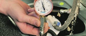
When the car begins to pick up speed poorly, drops in speed when you sharply press the gas pedal, or simply has unstable engine operation, you need to check the pressure in the fuel rail. If the pressure is less than 2 bar, the pump must be replaced.
The normal pressure of this fuel pump is 2.5 - 3.5 bar.
Replacing the fuel pump on VAZ-2113, 2114, 2115
It is commonly said that the heart of a car is its engine.
This is not entirely true, because a motor is an engine, that is, it should rather be compared to muscles, but a heart can, without a doubt, be called a gas pump. As soon as he stops, the car itself stands dead. You can drive to the nearest service center with three cylinders, a broken radiator, and a non-working generator, if you know how to do it. Without a fuel pump - only with a tow truck or on a cable. True, there are stories about how some craftsmen were able to connect a glass washer reservoir to the fuel system by pouring gasoline into it, but this is such an exotic thing that repeating it is dangerous both for the life of the car and for your own.
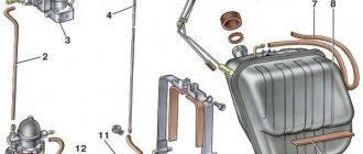
Pinout of fuel pump VAZ 2107
1 – radiator fan drive motor; 2 – mounting block block; 3 — idle speed sensor; 4 – engine ECU; 5 – potentiometer; 6 – set of spark plugs; 7 – ignition control unit; 8 – electronic crankshaft position sensor; 9 – electric fuel pump; 10 – indicator of the number of revolutions; 11 – lamp for monitoring the health of electronic systems and the brake system; 12 – ignition system control relay; 13 – speedometer sensor; 14 – special factory connector for reading errors using the BC; 15 – injector harness; 16 – adsorber solenoid valve; 17, 18, 19,20 – fuse box for repairing the mounting block that protects the injection system circuits; 21 – electronic fuel pump control relay; 22 – electronic relay for controlling the exhaust manifold heating system; 23 – exhaust manifold heating system; 24 – fuse protecting the heater circuit; 25 – electronic air sensor; 26 – coolant temperature control sensor; 27 – electronic air damper sensor; 28 – air temperature sensor; 29 – pressure control sensor and low oil pressure lamp.
You can check the fuel pump on a VAZ 2107 simply by checking the voltage at its connection block with a tester. The presence of voltage will indicate a malfunction of the electric motor. Instead of a tester (multimeter), you can use a test lamp to diagnose a malfunction.
In the absence of one, this can be done by disconnecting the connection block for the fuel pump and fuel level control and applying voltage with wires from the battery to the place where the gray wire is connected +12 and to the place where the black wire is connected - minus. A humming pump will indicate a faulty fuse, power circuit or ECU.
Checking the electrical circuit
Unlike a carburetor engine, where the fuel pump is mechanically driven, on the injection VAZ 2110/2112 a special relay and fuse are responsible for the operation of this device. Therefore, before moving on to diagnosing the pump itself, it is necessary to check the indicated elements. If any one of them is faulty, the pump will not work at all.
Turn on the ignition without starting the engine and listen. When the fuel pump is running, it emits a characteristic “whistle” when started. If it is not there, it means that either the pump itself has failed, or one of the elements of its power supply circuit has failed.
The pump relay and fuse are located in an additional mounting block located inside the vehicle's center console. It can be accessed by removing the plastic trim (near the front passenger's left foot). It is secured with several screws. Under the cover you will find three relays and three fuses. Typically, the fuel pump circuit protection elements are located centrally.
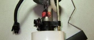
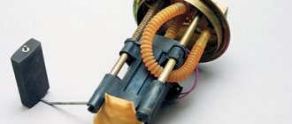
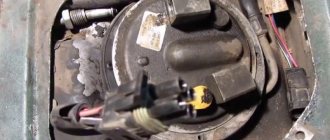
Removing and installing the fuel pump
Removing and installing the fuel pump is a simple operation. The fuel pump, together with the gaskets, is mounted on two studs and secured with nuts, which must be unscrewed with a 13 mm wrench. To remove the fuel pump, you need to disconnect the supply and discharge fuel lines, unscrew the fuel pump mounting nuts, remove the spring washers, and then the fuel pump itself.
When removing it, be careful, as you can damage the thin gasket, which often sticks to both the pump and the thick heat-insulating gasket. The thermal insulation gasket itself, as a rule, can be easily removed by hand without the use of any tools. In the worst case, make it easier to remove by lightly tapping it with the handle of a screwdriver. Do not forget also that under the thick thermal insulation gasket there is another thin installation gasket, which is also a sealing gasket.
Installing a repaired fuel pump has its own characteristics. First of all, install a sealing gasket A with a thickness of 0.70-0.80 mm, and then a heat-insulating one. Next, install a thin gasket B with a thickness of 0.27–0.33 mm.
With such a set of gaskets between the fuel pump body and the cylinder block, the minimum output of the pusher (its inner end touches the back of the cam) should be in the range of 0.8-1.3 mm. This dimension (d) can be easily checked by installing spacers and a pusher (rod). If the pusher protrudes from the gaskets by an amount less than 0.8 mm, then gasket A is replaced with gasket B with a thickness of 0.27-0.33 mm.
In the case where the pusher protrudes more than 1.3 mm, instead of gasket A, it is necessary to install a thicker gasket type C with a thickness of 1.20-1.30 mm. It should be clarified that a gasket with a thickness of 0.27-0.33 mm should always be installed between the fuel pump body and the heat-insulating gasket.
Why might the mesh need to be replaced?
Two grids - dirty and clean
First of all, because of bad gasoline. If you regularly refuel at dubious gas stations, then it’s only a matter of time before the fuel pump fails . Purification of gasoline from impurities in the gasoline pump occurs in several stages, and the mesh of the gasoline pump is the first line of defense, so to speak. It is the first to absorb all large particles of impurities and dirt. After passing through the mesh, gasoline enters the fine fuel filter, then passes through another mesh (which is located near the fuel pressure regulator), and finally goes through the third mesh (located directly in front of the injectors). If problems arise in any of these areas, you won’t be able to go far. The car engine simply will not start. Or it will start, but will work unevenly and jerkily.
recommends changing fine filters every 30,000 kilometers . But he doesn’t give any recommendations about the fuel pump mesh. Therefore, many car owners forget to change this grid, and remember about it only when the engine begins to behave strangely.
The general rule is: if the car has traveled 60,000 kilometers, the mesh should either be cleaned or replaced. It is advisable to clean it only if there is no serious mechanical damage to it. But if the machine has traveled the distance indicated above, then the mesh in the pump is often worn out to such an extent that it is easier to throw it away than to clean it.
Sequence of repair work
Installing the cylinder head
Also need a new head gasket and valve cover gasket. Having all this, you can begin the renovation. The sequence of actions for repairs is as follows:
- The car is placed in the garage, the gearbox is set to neutral, and chocks are placed under the rear wheels. The first thing that is done after setting up the car is to de-energize the on-board network by disconnecting the “-” terminal from the battery.
- The pressure in the fuel system is relieved. For this purpose, there is a control valve on the fuel rail in the form of a regular tire valve. You need to place a container under this valve and clamp the spool. When the pressure is released, gasoline will leak out. You will also need to drain the coolant using drain plugs.
- On the engine, you need to set the piston of the 1st cylinder to the TDC position. To do this, remove the protective cover of the timing belt and rotate the crankshaft until the marks on the pulley, camshaft and flywheel match.
- The next step is to remove the valve covers. To do this, all pipes, the throttle drive rod, the accelerator drive bracket and the valve cover mounting nuts are disconnected from the cover fittings.
- The exhaust pipe of the exhaust gas removal system is disconnected from the exhaust manifold. These works are carried out under the car.
- The wiring is disconnected from the mass flow sensor, the air supply pipe to the throttle assembly is removed, after which it is completely dismantled along with the air filter housing.
- Then you need to disconnect from the head all the elements suitable for the head - pipes of the cooling system of the throttle assembly, vacuum booster, throttle drive linkage, ground wires, bracket for the exhaust manifold supply pipe.
- The intake manifold strut mounts are also loosened, and the struts themselves are removed. Next, the wiring is disconnected from - oil pressure sensors, coolant temperature and throttle position sensors, XX regulator, injectors, high-voltage wires from spark plugs.
- Then the timing belt is removed. Before this, you need to once again check the alignment of the marks on the crankshaft pulley and the timing gear. After this, the belt tension is loosened and it is removed from the timing gear.
- To remove the camshaft gear, you will need to fix it through the technological holes and unscrew the fastening bolt. You need to remove it from the shaft carefully so as not to lose the key. After this, you will need to remove the rear cover, located behind the removed gear, from the head and block.
- The cooling system pipes are removed from the head along with the thermostat from the head, as well as the rest of the wiring. The fuel supply and drain pipes are also disconnected.
- All that remains is to unscrew the head bolts. But to do this, they must first be weakened, and in a strictly defined order. And only after relaxation do they completely unscrew. If disassembly is done correctly, after removing the bolts, you can remove the head and remove the damaged gasket. At this point, the first part of the repair is considered complete.
Before you begin the process itself, you need to decide on the necessary tools. So, what will you need: a ratchet and sockets for 17, 19; screwdrivers with flat and Phillips tips; a set of keys and the gasket itself.
Now that everything is prepared, you can start working directly. In order for the manifold to be removed without any problems and rusted bolts not to create trouble, everything must be lubricated with WD-40 before performing the operation. It is advisable to do this several times. Before performing the operation, you need to think again, weigh everything and calculate your strength.
Performance check
Checking its performance will help make sure that the fuel pump has failed. For this you will need:
- screwdriver with Phillips bit;
- a piece of gas-resistant hose (50–80 cm) with a clamp;
- key to 17;
- empty 2 liter plastic bottle;
- a piece of insulated wire;
- stopwatch.
Performance testing is carried out as follows:
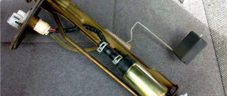
- We remove the back seat. We lift the carpet and find the gas tank hatch under it. Unscrew the two screws (diagonally).
- Once you remove the hatch, you will see the top of the fuel module. Using a 17 wrench, unscrew the nut of the outlet fitting. We put a hose on it and secure the connection with a clamp. We lower the other end of the hose into an empty bottle.
- Disconnect the pump power connector. Using a piece of wire, we supply power to the positive contact of the device from the corresponding battery terminal. We connect the negative one to ground.
- We begin counting the time from the moment the pump starts.
A working fuel injection pump for a VAZ 2110/2112 should pump 1.5 liters of fuel in one minute. If this indicator is lower, the pump must be replaced.
Which fuel pump to install on a VAZ 2114
On the VAZ 2114 and others of this family, they are installed from Bosch or Denso, since the original fuel pump only comes complete with a module (article 21102-1139009-02). Other manufacturers may be preferred only for reasons of economy.
| Manufacturer | vendor code | Average price, rub. |
| SAT | STFP06 | 799 |
| MEAT DORIA | 76416 | 1056 |
| DENSO | DFP0105 | 2504 |
| BOSCH | 580453453 | 2899 |
Tool required for work
- 10mm wrench;
- Screwdrivers “+” and “-“;
- Construction hair dryer;
- Pliers;
How to Test a Mechanical Fuel Pump
To check a mechanical fuel pump, you will need the following tools and tools:
- screwdriver with Phillips bit;
- slotted screwdriver;
- key (head) 10;
- key to 13;
- 2 clean dry plastic bottles with a volume of 2 liters;
- a piece of hose (50 cm) of the same diameter as the fuel one;
- 1–1.5 liters of gasoline;
- caliper (ruler);
- stopwatch (clock).
Let's start with performance. A working VAZ 2110 mechanical fuel pump with a obviously clean filter should pump at least 1 liter of fuel per minute. The verification algorithm is as follows:
- We lift the hood and find the pump.
- Using a screwdriver, unscrew the screw of the pump outlet hose clamp. Loosen the clamp and remove the hose from the pump fitting.
A performance test involves measuring the amount of fuel pumped over a specified period of time.
If the amount of fuel pumped in 1 minute is less than 1 liter, the fuel pump is faulty
If the amount of fuel pumped per minute is less than a liter, the pump is faulty. The reasons for this may be:
- faulty valves;
- rupture of one or more membranes;
- clogging of the pump grid;
- wear of the drive rod (pusher).
We carry out further checks in the following order:
- Disconnect both fuel line hoses from the pump.
Disconnect the inlet and outlet hoses
When you press the manual pumping lever, you should feel a vacuum at the inlet fitting, and a pressure of air at the outlet
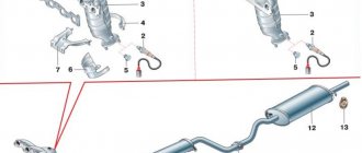
Design features of the engine on the VAZ-2114
Valve cover gasket replacement process
Before moving directly to the process, you need to know some structural elements of the VAZ-2114 engine.
The valve cover gasket is located directly under the cover itself and this can be clearly seen in the diagram below.
So, first, let's look at what the engine consists of:
Diagram of internal combustion engine components
| № | Detail number | Part name |
| 1 | 2108-1003298 | screw |
| 2 | 2108-1003278-01 | Washer |
| 3 | 2108-1003277-01 | Sleeve |
| 3 | 2108-1003277-02 | Sleeve |
| 4 | 2108-1003274 | Cover pin |
| 5 | 2111-1003260 | Cylinder head cover |
| 6 | 2108-1003271 | Bolt M12x1.25x135 |
| 7 | 2108-1003265 | Washer |
| 8 | 14328201 | Plug 10 cup |
| 9 | 14329101 | Plug 30 cup |
| 10 | 1118-1003011 | Cylinder head |
| 11 | 2101-1002042 | Sleeve |
| 12 | 14329201 | Plug 36 cup |
| 13 | 10158601 | Plug 16 spherical |
| 14 | 11183-1002011-10 | Cylinder block |
| 15 | 14234330 | Bolt M10x1.25x65 |
| 16 | 2108-1003284-10 | Ring sealing |
| 17 | 2111-1003284 | Ring sealing |
| 18 | 2111-1003286 | Bolt |
| 19 | 2111-1003288-10 | Stub |
| 20 | 10725911 | Nut M6 low |
| 21 | 11197773 | Conical spring washer 6 |
| 22 | 13541221 | Hairpin M6x22 |
| 23 | 2108-1003270-10 | Cover gasket |
| 23 | 2108-1003270-11 | Cylinder head cover gasket |
| 24 | 21083-1003020-10 | Head gasket |
| 24 | 21083-1003020-11 | Head gasket |
| 25 | 2112-3855020 | Knock sensor |
| 25 | 2112-3855020-01 | Knock sensor |
| 25 | 2112-3855020-02 | Knock sensor |
| 25 | 2112-3855020-03 | Knock sensor |
| 26 | 2101-1002040 | Sleeve |
Article: 21082-1101138, additional articles: 21082-1101138Р
Order code: 023299
- Buy with this product
- show more
- Passenger cars / VAZ / VAZ-21081 drawing
- » href=»/catalog/vaz-3/legkovye_avtomobili-30/vaz_2108-18/bak_toplivnyiy-79/#part27994″>GasketPower system / Fuel tank
Passenger cars / VAZ / VAZ-21111 drawing
» href=»/catalog/vaz-3/legkovye_avtomobili-30/vaz_2111-11/bak_toplivnyiy-114/#part44927″>Gasket Power system / Fuel tank
Passenger cars / VAZ / VAZ-21151 drawing
» href=»/catalog/vaz-3/legkovye_avtomobili-30/vaz_2115-65/bak_toplivnyiy-79/#part53067″>GasketPower system / Fuel tank Passenger
cars / VAZ / VAZ-2110, 2111, 21121 drawing
» href=»/ catalog/vaz-3/legkovye_avtomobili-30/vaz_2110__2111__2112-415/bak_toplivnyiy-124/#part1302975″>Gasket Power system / Fuel tank
Passenger cars / VAZ / VAZ-21131 drawing
» href=»/catalog/vaz-3/legkovye_avtomobili-30 /vaz_2113-648/bak_toplivnyiy-16/#part1669107″>GasketPower system / Fuel tank
Passenger cars / VAZ / VAZ-21101 drawing
» href=»/catalog/vaz-3/legkovye_avtomobili-30/vaz_2110-10/bak_toplivnyiy-114/ #part40619″>GasketPower system / Fuel tank
Passenger cars / VAZ / VAZ-21121 drawing
» href=”/catalog/vaz-3/legkovye_avtomobili-30/vaz_2112-12/bak_toplivnyiy-114/#part49235″>GasketPower system / Fuel tank
Passenger cars / VAZ / VAZ-2120 “Nadezhda”1 drawing
» href=”/catalog/vaz-3/legkovye_avtomobili-30/vaz_2120__nadejda_-245/bak_toplivnyiy-70/#part55816″>GasketPower system / Fuel tank
Passenger cars / VAZ / VAZ-21141 drawing
» href=»/catalog/vaz-3/legkovye_avtomobili-30/vaz_2114-647/bak_toplivnyiy-16/#part1669107″>Gasket Power system / Fuel tank Passenger
cars / VAZ / VAZ-21091 drawing
» href=»/ catalog/vaz-3/legkovye_avtomobili-30/vaz_2109-701/bak_toplivnyiy-17/#part1929931″>GasketPower system / Fuel tank
- There are no reviews for this product yet.