This article is located at: https://www.semerka.info/node/164. I agreed with the author on copying the article to the NIVA-FAQ website and sent it to Sergey_SS.
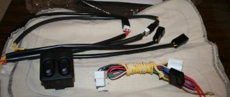
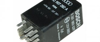
The standard VAZ windshield wiper works great in heavy rain, but in light drizzling rain, unfortunately, its performance cannot be called good, I’m talking about those moments when it works intermittently. The standard pause between wiper sweeps is 4 seconds. Very often, when the rain is very light, the glass does not have time to get wet, and the wipers practically work dry. The driver, cursing AvtoVAZ employees in native Russian expressions, will need to turn the windshield wiper on and off himself every 5-10-20 seconds. In general, I think any VAZ owner understands what I want to say. And today we will fight this problem. So, we remove the windshield wiper relay from the car, disconnect the block and take it home:
Open the lid and disconnect the printed circuit board from the lid. Let's look at the diagram. The resistor circled in red is responsible for the pause between sweeps of the wiper:
By changing its resistance, you can and even need to adjust the pause between sweeps of the wipers. The resistor itself is 62 Kohm, which equals 4 seconds between strokes. If you are satisfied with a minimum delay time of 4 seconds, then you can leave this resistor. I had a 47 kOhm resistor, and I installed it so that the minimum delay time was 3 seconds. If you set it to 25-30 kOhm, the delay time will be about 2 seconds. So, if you decide to leave the original resistor, then solder any one of its legs from the board; if you change the resistor to a lower value, then solder the original resistor, and solder the new one with only one leg. We take half a meter of two-core wire (or two single-core wires) and solder one wire to the free leg of the resistor. And the second wire goes to the place where the freed leg was removed. Like this:
The wires in the photo are covered with a transparent heat-shrinkable casing - a very convenient and effective method of insulation. We simply put the tube over the connection and heat it slightly with a lighter, the tube shrinks in diameter and settles tightly on the connection, this is much more effective than electrical tape.
So now we have two wires soldered, we make a knot on them so as not to accidentally tear them off, and close the lid, pulling our wires along with the standard ones. Glue the relay cover. I personally glued with a hot glue gun:
Next we take a variable resistor:
The resistor value can be any from 100 kOhm. The higher the denomination, the longer you can pause between brush strokes. For example, if the resistor is 100 kOhm, then the maximum interval between brush strokes will be about 10 seconds. If you take 200 kOhm, the interval will be about 17 seconds and so on. The only thing is that I don’t recommend taking more than 500 kOhm, because the accuracy of setting the interval will decrease. So, we take a resistor and solder one wire (any) to the middle contact, and the second to any extreme one.
The whole device is ready:
We take everything back to the car. We put the relay in its rightful place, and place the resistor where it is more convenient for you. I personally placed it on the steering column next to the windshield wiper switch. IMHO this is more logical and correct. And he put on it the knob from the stove regulator from the figure eight:
That's it. Everything is ready. Now in intermittent mode, the time between wiper strokes is adjustable from 3 to 10 seconds, the resistors are 47 kOhm (0.25 W) and variable 100 kOhm 0.25 W. In terms of watts, you can take any resistors (but 0.25 is a convenient size for us). In the future, I’m thinking of changing the resistors to 30 kOhm - to make the minimum pause time 2 seconds and variable to 200 kOhm or 500 kOhm, to make the maximum pause time longer, up to 17-18 seconds with a 200 kOhm resistor or almost up to a minute with a resistor at 500 kOhm Everything described in the article was modified using the PC-514 wiper relay - this is what is installed on most cars, but if you have another relay, then I think that it can be modified in the same way.
Thoughts about the “regulated pause” have been tormenting me for a long time, but the “sudden arrival” of spring “nudged me”, and I went to the Internet for a ready-made solution to this issue. Of the many different options, the above material was recognized as one of the best in terms of speed, ease of execution and budget. The picture was slightly overshadowed by the fact that my “native” relay turned out to be an “old” model - also with a thermocouple, which slightly increased the budget of the event, but, on the other hand, for the period of experiments I did not have to give up the usual wiper mode.
A new RS-514 relay was purchased at a nearby store, but it also turned out to be not the same relay as described above (as it turned out, there are several modifications that are not designated in any way.), although on the same microcircuit. After sitting for a while on the new relay board, I found an analogue of the “resistor circled in red.” This is R2 with a nominal value of 33 kOhm:
Resistor R2 was mercilessly discarded due to inconvenience of use. For me, given the lack of a soldering iron with a power of less than 100 W, it was more convenient to solder a constant resistor to the lower “contact” of VD2 (left contact R2 in the photo), and the wire to the “+” of the capacitor (one track with the right contact R2). With a constant resistor of 30 kOhm and a variable resistor of 200 kOhm, the minimum pause was about 4.5 seconds, the maximum - 32 seconds.
The total budget for “refinement” (as of March 2011): imported resistor, with inertial lubrication and with a handle - 35 rubles, new relay - 100 rubles, permanent resistor - 2 rubles, wire, piece of heat-shrinkable tube, soldering iron and, of course, hands.
In the new 0 I decided to make an adjustable pause in the wipers, removed the standard relay, but it turned out to be not a PC514, but a relay from the seven 2107-3747.
An autopsy showed that the circuit was assembled on a special K1055GP5R microcircuit, which is a complete analogue of the Philips MC33197 microcircuit. The data sheet for it is here: https://www.allcomponents.ru/pdf/motorola/mc33197.pdf.
Now about the alteration. You need to unsolder the 4.7 kOhm resistor, drawn in red:
I took the picture after the alteration, so I finished drawing it. Instead, I soldered wires, on the other end of which I soldered a series-connected constant resistor of 1.5 kOhm and a variable resistor of 22 kOhm. The pause began to be adjusted from 0.5 seconds to 19 seconds.
Analysis of the datasheet showed that the use of this microcircuit gives us the opportunity to implement the function of automatically turning on the continuous operation of the wipers when the glass washers are turned on. To do this, you need to connect pin 5 of the microcircuit through a 4.7 kOhm resistor to the positive of the washer motor. Where and what to solder is shown in the photo:
The upper and lower yellow wires go to the pause control resistors, the middle one with a soldered resistor in heat shrink goes to the plus of the washer motor.
Now, if when the wipers are operating in intermittent mode. If you turn on the windshield washer at the same time as turning on the washer motor, the windshield wiper will automatically switch to continuous mode; after the supply of washer fluid stops, the wipers make three more strokes and automatically switch back to intermittent mode.
Modernization of windshield wipers. Automatic windshield wiper.
V. Lomanovich, A. Kuzminsky
Windshield wipers installed on some modern cars operate continuously. However, it is rational to equip the windshield wiper with an appropriate automatic device that ensures that it is periodically turned on and off according to a given program. In Fig. Figure 1 shows a diagram of an electronic device for automatically turning on the windshield wiper at a specified frequency.
Rice. 1. Schematic diagram of devices for automatically turning on the windshield wiper
The multivibrator on transistors T1 and T2 generates rectangular pulses, which are fed to the base of transistor T3, in the collector circuit of which the electromagnetic relay P1 is connected. The duration of the pulses arriving at the input of transistor T3 varies from 1 to 30 s depending on the position of the variable resistor R2 slider, and the operating period of relay P1 changes accordingly. Normally closed contacts 1P1 and 2P1 of relay P1 are connected in parallel and are used to control the windshield wiper motor.
When connecting an electronic machine to a standard windshield wiper, you need to disconnect clamp “3” from the chassis so that in the future contacts 1P1 and 2P1 of relay P1 (see Fig. 1) can be connected to point “3” and the chassis (common minus). At the same time, it remains possible to operate the windshield wiper in normal (non-automatic) mode.
After applying voltage to the electronic device, relay P1 is activated and contacts 1P1 and 2P1 break the power supply circuit of the windshield wiper motor 0.3-0.5 s after the closure of toggle switch B1. The time during which the electric motor is turned off depends on the duration of the control pulses arriving at the base of transistor T3 from the multivibrator (see Fig. 1).
Timing relay for windshield wiper
Many older cars are not equipped with a time relay for intermittent wiper operation, which creates inconvenience during their operation. Modern cars already have such devices, but they are designed for only one pause time and the ability to adjust it depending on road conditions is not provided. Below is a simple diagram of a time relay, the assembly of which is accessible even to a novice radio amateur. Thanks to the use of a unijunction transistor, the device has independent response time from changes in supply voltage and ambient temperature. In Fig. Figure 1 shows a diagram for connecting breaker U1 to the windshield wiper motor circuit U2 through a toggle switch with a neutral middle position B1.
Rice. 1, Circuit diagram for connecting a breaker to the motor circuit Fig. 2. Schematic diagram of a time relay based on a unijunction transistor.
Instead of toggle switch B1, two switches can be used separately for continuous and intermittent operation.
The breaker works as follows. When switch B1 is set to the “Prer” position, almost the entire supply voltage is applied to the time relay. At this time, the wiper blades are in their original position, and the contacts of limit switch B2, controlled by electric motor M1, are open. Through resistors R2 and R3 (Fig. 2), capacitor C1 begins to charge.
The time constant of the chain R2 R3 C1 determines the pause time. When the voltage on capacitor C1 reaches the operating voltage of transistor T1 (after a pause time), the pulse C of this transistor will go through resistor R5 to the control electrode of thyristor D2 and open it. Electric motor M1 begins to rotate and closes the contacts of limit switch B2. During the engine's operating stroke, until the brushes return to their original position, contacts B2 remain closed. During this period, capacitor C1 is discharged through resistor R1 and diode D1. When the brushes return to their original position, contacts B2 open, electric motor M1 stops, and the whole cycle repeats again. Capacitor C2 serves to increase the noise immunity of the time relay.
With the values of the elements R2, R3 and C1 indicated in the diagram, the pause time can vary from 1-2 to 5-7 s. To increase the pause time to 10-15 s, it is necessary to increase the resistance of resistor K2 to 100 kOhm.
In Fig. Figure 3 shows a time relay circuit based on a transistor analogue of a unijunction transistor.
Rice. 3. Schematic diagram of a time relay based on a transistor analogue of a unijunction transistor
The circuit can use resistors of any type, capacitors C1, C2 - electrolytic, type K50-6, K52-1, K52-2, K53-1, ETO, etc., diode D1 - silicon, type D219, D220, D223, KD503, KD504, KD510, etc. Thyristor D2 - type KU201 or KU202 with any letter index. Unijunction transistor T1 (see Fig. 2)—type KT117 with any letter index. Transistor T1 (see Fig. 3) is type MP106 or MP116, transistor T2 is type MPI102. MP103, MP113, KT315, KT342, KT602 or KT603.
Structurally, the time relay is placed in a small box installed behind the dashboard of the car so that the driver has access to the variable handle of resistor R2. A schematic diagram of the relay circuit board is shown in Fig. 4.
Rice. 4. Printed circuit board of a time relay: a - placement of parts of the relay circuit on a unijunction transistor; b - placement of parts of the relay circuit on the transistor analogue; c—printed wiring of a relay circuit on a unijunction transistor; d - printed wiring of a relay circuit on a transistor analogue
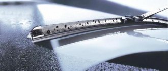
Windshield wipers, better known as windshield wipers, are not vital vehicle systems. But their breakdown causes serious inconvenience in bad weather and threatens traffic safety due to poor visibility. Fortunately, most windshield wiper malfunctions can be fixed fairly quickly with your own hands; repairing them is much easier than, say, repairing an automatic transmission.
Windshield wipers, better known as windshield wipers, are not vital vehicle systems. But their breakdown causes serious inconvenience in bad weather and threatens traffic safety due to poor visibility. Fortunately, most windshield wiper malfunctions can be fixed fairly quickly with your own hands; repairing them is much easier than, say, repairing an automatic transmission.
Repair
To troubleshoot problems with the wipers on your VAZ 2109, it is not at all necessary to contact a service station. The work can be done with your own hands, saving a decent amount of money.
Repair consists of performing several operations:
- Disassembling the unit;
- Troubleshooting;
- Eliminating the causes of purifier failures;
- Reassembly.
Dismantling
The first step is to learn how to remove windshield wipers. This will give you access to the device and all its components.
Dismantling by a wiper is carried out for their repair, replacement, modernization or when working with other components of your car.
It is enough to follow the specified sequence of actions and first familiarize yourself with the wiper diagram in order to do everything correctly.
Scheme
- First, disconnect the negative terminal of the battery to de-energize the car.
- Remove the brush arms by moving them to a vertical position and unscrewing the fastening nuts. Unscrew the nuts carefully so as not to push the lever out. Otherwise, under the action of the spring, it will fly into the glass and break it.
- By unscrewing the fasteners, the levers can be removed. It is not always possible to do this manually, so arm yourself with pliers. Be careful not to damage the threaded area. To avoid this, screw the nut back onto the splines, but not completely.
- Remove the protective caps made of plastic from the slots on each side.
- Unscrew the upper mounting nuts with the bracket and remove them. Under them there are rubber washers, which are also dismantled.
- Lift the hood and disconnect the wiring harness that powers the wiper motor.
- Unscrew the heater fan mounting screws and move it slightly to the side. This way, when dismantling the purifier, it will not interfere with you.
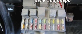
- Remove the cover from the relay and fuse box. You need to remove not only the wiper relay, but also everything else. Otherwise, they will interfere with your further processes.
- Unscrew the lower fastening nut of the mechanism, remove the plastic holder of the wiring harness from the electric motor from the hole in the car body. Now you can remove the holder so that it does not get lost during the repair.
- All that remains is to push the mechanism roller inside, then lift the electric motor and the windshield wiper mechanism slightly up and to the side. This way you can easily remove the node.
How do wipers work?
The windshield cleaner consists of several elements:
- electric motor with gearbox (gearmotor);
- relay with switching contacts for changing operating modes;
- lever drive;
- hinged fastenings;
- pairs of pendulum arms to which brushes are attached;
- brushes that clean glass.
The windshield wiper motor can be powered by a battery or generator, and is switched to an available power source by a relay. The power supply circuit of the gearmotor varies depending on the car model.
In modern cars, the operation of the gearmotor is controlled by an on-board computer, so it is better to repair or replace it at a car service center, and limit independent work to replacing the brushes.
Thanks to the purifier relay, the motor can operate in several modes:
- intermittent (after making one double stroke, the brushes remain in the lower position, and after 3–5 seconds they repeat the movement);
- constant, with low or high brush speed;
- Some models have a separate washing mode (with the washer on).
The gearmotor is the most complex component of a windshield wiper. It consists of an armature with a winding, blocks, wires, gears, a limit switch with a spring plate and a stand. It may also include a reusable thermobimetallic fuse for overload protection.
Through the lever drive system, the rotational energy of the motor is converted into pendulum-like movements of the levers, and the brushes move with them. Each describes a semicircle, and the rubber or silicone tape, pressing against the glass, removes moisture and dirt. Sometimes the cleaner must be used in combination with glass washer. The design of the front and rear window wipers is generally similar, but the rear does not use a relay, so the set of operating modes is different.
Brushes have different designs. They are:
- frame, with movable rocker arms, ensuring the tightest possible pressing of the cleaning tape to the glass;
- frameless, in which the cleaning edge is attached to a rigid metal base, and the curvature of the edge bend is provided by a spring mechanism.
Electrical part
It includes:
- The electric motor of the windshield wiper itself;
- Windshield washer motor;
- The windshield wiper and washer switch is located under the steering wheel of the VAZ 2110;
- The main and additional relays are located in the mounting block and provide cyclic operation of the wipers;
- Bimetallic fuse is thermal in type; its limit switch is located in the gearbox of the windshield wiper motor.
Typical glass cleaner malfunctions
Malfunctions in the operation of the windshield wiper may be associated with a breakdown of the gear motor, relay, switch, as well as wear or deformation of mechanical parts. The most common problems that arise are:
- the electric motor does not turn on (the characteristic noise accompanying its operation is not heard);
- the operation of the electric motor stops due to the fuse tripping;
- the engine does not go into intermittent or wash mode;
- in intermittent mode, the brushes move without stopping;
- pendulum arms and brushes do not move when the gearmotor is running;
- wipers move too slowly, with difficulty;
- brushes do not return to their original position;
- The brushes move, but the cleaning is unsatisfactory.
Video “Features of replacement”
How to replace cleaners without a puller and what you need to take into account - learn from the video (author - AssistanceTV channel).
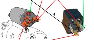
Drivers of the “Seven” are aware of the problem with the operation of the windshield wiper, which does not consist in frequent breakdowns, but in the fact that the cyclical movement of the wipers makes them nervous. But, more on that a little later. In general, the relay plays a very important role, and such a role appears only in rainy weather. After all, the operation of wipers is impossible not only without power, but also without a regulator. It is the relay that performs this function, which provides great convenience during bad weather. But this is not the only function of this device, however, this is described below.
Trouble-shooting
Poor quality of glass cleaning is usually associated with wear of the cleaning tape, as well as contamination of the hinges in the frame brushes and limited mobility of the rocker arms. The easiest way to solve this problem is:
- In frame brushes, the cleaning tape is changed. The brushes must first be dismantled, the worn element removed, a new one installed in its place, secured with steel plates and the brush secured to the lever.
- Frameless brushes are replaced entirely.
Sometimes the tape is in good condition, but the brushes leave streaks because the grooves that hold the tape are clogged. In this case, they should simply be cleaned. If the metal frame is covered with rust and the rocker arms have lost their mobility, it is better to replace the brushes entirely.
Cleaning tape is inexpensive, but some motorists are in no hurry to change it. You can restore the elasticity of the tape by dipping it in gasoline and washing it with a warm soapy solution; after this procedure, it is useful to coat the tape with silicone grease. Traces of grease are easily removed with white spirit. A worn, rounded edge can be smoothed out using fine-grit sandpaper glued to a hard base.
Slow movement of the wipers may be due to:
- With wear of the gear motor. It must be disassembled, cleaned, lubricated, and if critical wear occurs, replaced.
- With corrosion, contamination, insufficient lubrication of moving joints. The entire mechanical part is dismantled, disassembled, cleaned, and lubricated.
- With an error made during the installation process that needs to be identified and corrected.
Incorrect assembly can also cause the wipers to not return to the park position. Another reason for this problem is wear or breakage of the drive splines, in which case they need to be replaced.
Problems in the operation of the electric motor can be associated with both its breakdown and mechanical problems. If the gearmotor itself is damaged, it is best to replace it entirely. But if the problem can be fixed by replacing the damaged gear, cleaning the dirty manifold, and adjusting the limit switch, replacement can be avoided.
If the engine does not turn on, you need to inspect the power wires, winding wires, commutator, brushes, as well as the steering column switch, which includes a wiper switch.
- Damaged power wires are replaced with intact ones, oxidized tips are cleaned.
- A failed switch is replaced.
- A dirty collector can be cleaned, the internal cavities can be blown out and the surface can be sanded.
- If the collector burns out, it is better to replace the gearmotor.
- Replacing the gearmotor is also recommended if the winding wires are broken, although only the armature can be replaced.
The engine shutdown due to the fuse tripping may be caused by a short circuit in the winding; in this case, the gearmotor must be replaced. But quite often, an emergency shutdown is associated with the locking of the brushes due to their freezing to the glass, deformation of the levers, or the entry of a foreign object into the mechanism. In this case, the cause must be eliminated. Frozen brushes are carefully separated from the glass using a scraper so as not to damage the cleaning edge, but it is better to wait until it thaws. The mechanism is cleaned of dirt and foreign objects that hinder its operation. Deformed drive elements are leveled, and if the deformation is severe, they are replaced with new ones. After eliminating the cause of the fuse tripping, the blown disposable fuse is replaced with a new one, and the thermobimetallic fuse can be used again.
Intermittent purifier problems are most often caused by a damaged relay or switch. If the brushes move intermittently without pauses, and everything is in order with the relay, the limit switch may not operate. In this case, you need to adjust it, bend the contacts or the spring plate, which the gear cam bends. It is also possible that the limit switch contacts are dirty and need cleaning.
When the brushes do not move when the engine is running, the problem lies in the gear motor gear; it is necessary to inspect the gear itself and the crank on its axis:
- if the gear teeth are broken, it needs to be replaced;
- If the crank fastening is loose, you need to tighten the nut to the limit.
Circuit breakers
Now let's see which fuses are responsible for what in the same mounting block. I will also give the main reasons for troubleshooting.
F1 (5 A) - license plate lighting lamps, dashboard lighting, side lights on the panel, trunk lamp, left side lights . If any of the listed lamps do not work, check this fuse, as well as the lamps themselves and their contacts. If everything is in order, check the headlight switch button.
F2 (7.5 A) - low beam in the left headlight . If both low beam headlights do not work, also check relay K4 and the lamps themselves. It could also be the light switch and its contacts.
F3 (10 A) - high beam in the left headlight . If both high beam headlights do not work, check the K5 relay, the lamps themselves and the high beam switch knob.
F4 (10 A) - front fog lamp on the right side . If both fog lights do not work, check relay 9 and the headlight bulbs themselves, as well as the switch and its contacts.
F5 (30 A) - window lift motors . If the power windows do not work, check this fuse and relay 5. In winter, check if the windows are frozen, warm them up and clear them of ice if necessary. It could also be the window lift motor, its mechanism and gears; in order to get to it, you need to remove the trim of the desired door.
F6 (15 A) - portable lamp fuse.
There may also be problems with the cigarette lighter. To check, unplug the cigarette lighter from the connector. If this fuse stops burning, then the problem is in the cigarette lighter.
F7 (20 A) - engine cooling fan, sound signal . If the cooling fan does not turn on and the engine overheats, check this fuse. Also check the operation of the fan motor by connecting it directly to the battery. It could also be the coolant temperature sensor or thermostat.
F8 (20 A) - heated rear window (element) . If the heating does not work and the rear window fogs up, check this fuse, fuse F9 and relay K7. Also check the contacts on the terminals of the heating elements, check the wiring, sometimes the wire frays. It could also be the heating switch and its contacts.
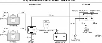
F9 (20 A) - recirculation valve, windshield wipers and washer, headlight washer, rear window heating relay coil . If the heating does not work, similar to the previous one. If the windshield wipers or washer do not work, also check relay K2, the fluid level in the washer reservoir, the washer pump, and the wiper motor. Another issue may be their switching handle, its wiring and contacts. The wires may be squashed or frayed and shorted to the housing.
F10 (20 A) - backup fuse.
F11 (5 A) - right side dimensions . If the left side does not work, check fuse F1. If none of the side lights work, check the light switch and its contacts. Also check the dimensions of the lamps themselves.
F12 (7.5 A) - low beam in the right headlight . Similar to fuse F2 for the left headlight.
F13 (10 A) - high beam in the right headlight, high beam lamp on the dashboard . Similar to fuse F3 for the right headlight. If the blue lamp on the panel does not light up when you turn on the high beams, check this fuse, as well as the lamp itself and the wiring to it.
F14 (10 A) - front fog lamp on the left side.
Similar to fuse F4 for the right fog light.
F15 (20 A) - seat heating, trunk locking . If the heated seats do not work, check this fuse and the power button on the dashboard, its contacts and wiring.
F16 (10 A) - direction indicators and hazard warning lights, hazard warning lamp . If the turn signals or hazard lights do not work, also check relay K3 and the lamps in the turn signals themselves, as well as the hazard light switch button.
F17 (7.5 A) - interior lighting, lighting, ignition switch lighting, brake lights, clock, on-board computer . If the brake lights do not work, check this fuse, the lamps themselves, and also the switch installed in the pedal unit.
F18 (25 A) - glove box lighting, heater controller, cigarette lighter . If the cigarette lighter does not work, check this fuse, disassemble the cigarette lighter and check for a short circuit in it, especially on the washer and contacts. Bend them if necessary or replace the entire cigarette lighter. Do not insert non-standard size connectors into it.
F19 (10 A) - door locks, control relay for brake lights and parking lights, turn signals and lamps for turning them on on the panel, reverse lamp, generator winding, control indication of the on-board system, dashboard, clock, on-board computer.
F20 (7.5 A) - rear fog lights.
If the rear fog lights do not work, check this fuse and relay 9. Also check the lamps themselves, wiring, connectors and the switch on the panel.
Never replace blown fuses with fuses of a higher rating (current), this can cause burnout of tracks on the mounting block, failure of devices, etc. In this case, repairs will cost more, so it is better to deal with the problem immediately and fix the problem. If you cannot find what’s wrong on your own, contact a car service; usually such problems are dealt with by electricians, who will not have any difficulty identifying the problem and fixing it.
Rear window wipers
Malfunctions in the operation of rear window wipers are usually associated with the steering column switch, gear motor, power wires, broken drive teeth, and worn brushes. The relay does not affect the operation of the rear wipers, so its malfunction can be ruled out. The methods for eliminating other breakdowns are the same as for the front wipers.
Repair of windshield wipers mainly comes down to replacing damaged components, cleaning electric motor parts, cleaning and lubricating moving joints, and straightening deformed levers. Repair costs are low, and using contract spare parts from JapZap will keep them to a minimum. The procedure for dismantling and installing different components of this assembly may differ in different cars, but the general principles for troubleshooting are the same.
Device design
The Gazelle is equipped with a windshield wiper mechanism with an electric drive, which ensures the operation of two wipers.
The design includes:
- electric motor;
- gearbox;
- bimetallic fuse;
- drive levers;
- brushes;
- ring switch.
The operation of the device is based on a worm gear, which connects the electric motor shaft, worm wheel, and drive levers into a single system. Control is carried out using a switch located on the steering column.