For all its popularity, the Niva 2121 has a number of disadvantages. One of the most common problems with this SUV is increased vibration in the cabin. Moreover, the more the car is used, the more noticeable the vibration becomes.
The reason for the increased vibration is a structurally incorrect solution for securing the transfer case (transfer case). The fact is that this box on the Niva is attached directly to the bottom using silent blocks. And since during operation the vibration of the transfer case is significant, all this is transmitted to the cabin.
As a result, strong vibration affects the transmission and it wears out faster. Although the metal of the bottom in the area where the transfer case is attached is reinforced, due to strong vibration, the bottom is destroyed over time due to exposure to vibration.
Often, Niva 2121 owners, in order to reduce vibration in the cabin, install a subframe under the transfer case. This device is made of metal. The Niva subframe absorbs any vibration impact from the transfer case.
The subframe has enough advantages:
- Receives the oscillatory movements of the transfer case.
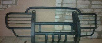
- Protects its body from possible damage when driving off-road.
- When installed correctly, there is virtually no displacement of the axis between the transfer case and the gearbox, which has a positive effect on the durability of both transmission units, as well as cardan and intermediate shafts.
Factory design
One of the recommended devices for eliminating transfer case vibration is the so-called “Niva Comfort” kit. The Niva Comfort subframe was developed a relatively long time ago, has a quality certificate, and Niva 2121 owners often use it.
This device is a welded structure made of metal corners, with drilled fastening points, mounting plates to which the base will be mounted. Since the transfer case should not be fixed rigidly to the base, the kit includes elastic supports.
For all its advantages, this subframe for the transfer case has disadvantages. It is installed in the places where the box was previously attached, that is, to the bottom, so if there are problems with the base, installing the Niva Comfort design will be problematic.
Eliminate vibration with additional fasteners
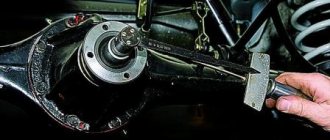
Installing the third support of the transfer case on VAZ 21213/21214 vehicles allows you to reduce the level of vibration of the transfer case; with this support it is easier to center the transfer case. The part can be purchased at auto stores or made yourself. The finished product comes with three long studs (for model 2121); to install the third support on this machine, you will need to unscrew the short studs from the transfer case housing and install new studs from the kit. We carry out repairs as follows:
- dismantle the front passenger seat in the cabin;
- remove the floor tunnel lining;
- in the cabin we move aside the carpet covering the body amplifier (in front of the handbrake lever);
- remove the transfer case (alternatively, you can simply hang it up, but removing the third support makes it easier to install);
- We attach the bracket of the new support to the body of the RC;
- we install the transfer case in place, center it in the optimal position, and fasten the side supports;
- we combine the third support with the body, drill two holes in the bottom;
- Using washers, bolts and nuts (from the kit) we attach the support to the bottom of the body.
Vibration is eliminated more effectively by installing a subframe under the transfer case. You can also make such a device yourself or buy a finished product at a car store.
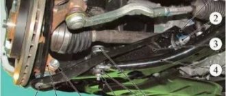
In order to install the subframe, the transfer case must be removed. It is more convenient to carry out such work in a pit; we carry out repairs as follows:
- leave the car in neutral gear;
- disconnect the propeller shaft from the transfer case, it is advisable to mark the driveshaft flange and the drive shaft so that during installation, align the driveshaft according to the marks - this way, the occurrence of unnecessary vibrations is eliminated;
- dismantle the muffler mounting bracket;
- remove the gearbox traverse;
- jack up the transfer case, remove the side fastenings of the transfer case;
- We treat the places where the subframe fits to the body with Movil;
- place the subframe on the gearbox studs;
- we mark the attachment points of the subframe on the side members, drill holes, attach bolts to the body;
- we tighten all fastenings, except for the transfer case supports themselves;
- we perform alignment of the steering wheel;
- Finally tighten the transfer case supports.
It should be noted that installing an additional support or subframe on the steering wheel does not always lead to the desired effect; in some cases, vibration only increases.
Homemade design
Many people make a similar subframe for the Niva on their own. First you need to make a drawing of the subframe. The simplest design consists of two crossbars and two crossbars connecting them.
The distance between the crossbars should be exactly the same as the distance between the transfer case attachment points to the bottom. Holes are made in the crossbars themselves to which the transfer case will be attached. To strengthen the structure, you can weld braces from metal corners in the inner corners between the crossbars and crossbars.
This design will be attached not to the bottom, but to the side members, so their length must correspond to the distance between the side members. Having made a drawing, you can create this device on the Niva with your own hands. Depending on the wishes of the owner, it can be made collapsible, bolted.
The advantage of such a subframe is the ability to replace a damaged element without removing the entire structure from the car. The disadvantage will be the need to constantly monitor the condition of the bolted connection. The welded structure of the subframe does not require constant monitoring, but if damaged, it will have to be completely replaced.
Next, you need to decide how the subframe under the transfer case will be attached to the side members. It is possible to attach it to the side surface of the subframe. To do this, you will need to drill through holes in the side surface at the mounting points.
The advantage of fixing it to the side surface of the spar is the ability to additionally install silent blocks at the fastening points, which will further dampen vibrations coming from the transfer case. The downside is the need to carry out additional calculations of the diameter of the bolts with which the structure will be attached to the spar, since in this case they will be subject to shear force. A bolt with a diameter that is too small will likely fail quickly due to vibration.
Removing the Niva transfer case
To repair the transfer case on a VAZ 21213 (21214), the unit must first be removed. We carry out removal in the following order:
- in the cabin we dismantle the plastic lining of the gearbox and gearbox levers;
- unscrew the knobs of the transfer case shift levers, remove the casing under them;
- disconnect the speedometer cable, for RK 21214 you will need to additionally disconnect the speed sensor;
- we unscrew the bolts with nuts securing the elastic coupling of the front and rear propeller shafts; in order to remove the bolts, the cardan shafts must be turned - they are removed one at a time in one specific position of the shaft;
- We install a jack (or other support) under the transfer case and mark the places where the side supports of the RC were attached. This is done in order to minimize the alignment of the transfer case during installation;
- unscrew the 4 nuts securing the gearbox to the gearbox;
- unscrew the 4 fastenings of the RC supports to the car body;
- Now all that remains is to dismantle the transfer case.
Manufacturing according to the scheme
Although the market has no shortage of offers, it is possible to save money by making a subframe for Niva 2121 with your own hands according to the drawings.
In the creation process, you will need a 4 mm sheet of cold-rolled steel 0.525x0.350 m, angles 35x35, 70x50, 70x70 with a length of 0.7 m, 0.4 and 0.4 m, respectively, as well as a 0.73 meter channel 16. Used as fasteners bolts M8, M10, M12x1.25 and M12x1.5. In the creation process you will need a 4 mm sheet of cold-rolled steel 0.525x0.350 m, angles 35x35, 70x50, 70x70 with a length of 0.7 m, 0.4 and 0.4 m, respectively, as well as a 0.73 meter channel 16. M8, M10, M12x1.25 and M12x1.5 bolts are used as fasteners.
Standard tool:
• Calipers and ruler;
An alternative tuning option is permissible using not corners, but a square profile with a section of 60x30 or 40x25.
There are ideas of placing the RC and the checkpoint on the same “frame”.
Preparation.
1. After the initial preparation of the elements, finishing processing and connection into a single structure is carried out: 1. In the channel, in accordance with the diagram, rectangular windows are cut out, ending no closer than 0.8 cm to the edge of the edge. Bevels (chamfers) are eliminated;
2. In corners measuring 70x50 or 70x70, holes are made for bolted connections, after which they are tacked by welding.
3. Corners of 35x35 cm are fixed to the lower edge of the channel, to which sheets are welded to protect against impacts and dirt. In the latter, for the purpose of access to the drain plug and regular cleaning, service holes are cut out.3. Corners of 35x35 cm are fixed to the lower edge of the channel, to which sheets are welded to protect against impacts and dirt. In the latter, service holes are cut out in order to gain access to the drain plug and regular cleaning.
Design modification.
To strengthen the subframe and reduce the profile height (up to 2 times), it is possible to additionally equip the side shelves of the channel with 4 corners at the level of the hole under the transfer case, followed by cutting off the sidewalls to the corner flange.
Finer tuning is provided by connecting the spar and subframe through couplings/bushings.
Installation
For ease of installation, the car is fixed on a lift or above a pit. Pre-preservation of surfaces (attachment points, subframe) is carried out using protective agents, for example, Movil.
The finished product is tried on site individually for each vehicle. 4 holes are drilled along the perimeter of the structure, symmetrical relative to the center line. Having previously loosened the transfer case fasteners.
Having placed the plates on the interior side, as in the photo, the subframe is attached to the side members with M12x1.25 bolts.
The RK brackets are sequentially removed, turned over and freely fixed to the subframe. The position of the shaft flanges is adjusted until minimal gaps are formed by moving the entire structure. Alignment is performed at 3000 rpm with the machine standing.
The bolts are thoroughly tightened.
Transfer case alignment
Correct installation of the transfer case can be done in several ways. Most often in auto repair shops, repairmen use the following method:
- hang the car on a lift;
- loosen the transfer case;
- start the engine;
- engage the gear and accelerate the car according to the speedometer to the speed at which vibration occurs (often it occurs at speeds from 40 to 80 km/h);
- without using the brakes, reduce the engine speed, then turn off the ignition.
The transfer case itself is centered in place, all that remains is to tighten the fastenings of the supports.
You can also adjust the position of the RC using a wire; we do it as follows:
- loosen all four fastenings of the transfer case supports;
- fasten one end of the wire to the rubber coupling of the propeller shaft;
- we attach another piece of wire to the CV joint, bring the other ends of the wire to each other;
- rotate the shaft; if the transfer case is not centered, the ends of the wire will diverge during rotation;
- the task comes down to installing the transfer case using the selection method so that the ends of the wire practically do not diverge from each other in any position when turning the shaft.
Installation of subframe step by step video
Video 2 off-road rides
Despite the fact that every year more and more new roads are gradually being laid in Russia, there is quite enough off-road in our area. Domestic motorists sometimes have to drive through areas where only an armored personnel carrier can pass. That is why in rough terrain there is a need for appropriate transport. The cheapest and most accessible SUV today is the VAZ 2121 Niva.
Transfer case Niva 21213
Model VAZ-21213 is an all-terrain passenger car with permanent all-wheel drive and differential lock. Brand 21213 is a restyled version of the first VAZ SUV, VAZ-2121. RK Niva 21213 has three gears:
- the first - with a gear ratio of 1.2;
- the second, lowered – with the number 2.135;
- neutral
21213 is equipped with 4-speed and 5-speed gearboxes, and when the first speed of the transfer case is turned on, the car operates in standard mode, the gear ratios in the transmission are from 5-speed. The checkpoints are as follows:
- 1 – 4,4;
- 2 – 2,52;
- 3 – 1,63;
- 4 – 1,2;
- 5 – 0,98.
When you turn on the second position of the transfer case lever (reverse position), the gear ratios change (lower):
- 1 – 7,83;
- 2 –4,48;
- 3 – 2,90;
- 4 – 2,14;
- 5 – 1,75.
On ordinary roads, the transfer case is always in first gear, the transfer case control lever (reduction gear) is pushed forward. The neutral gear of the RK disconnects the transmission, and in this position the car does not drive; there is also a neutral in the gearbox.
Motorists often ask the question: why is neutral gear needed in a transfer case? The neutral is used when connecting additional units to the transmission, for example, a mechanical winch; in this case, a power take-off must also be installed.
Benefits of use
A device such as a subframe has many advantages, the main one of which, as we have already noted, is the reduction of noise and vibrations in the cabin. In addition, this device is the only protection for the lower part of the transfer case.
By the way, on the conveyor the Niva is already equipped with special fastenings to the floor, which allow mounting supports on the transfer case. Thus, installing a transfer case subframe on a Niva will take the car enthusiast no more than 30 minutes. Another thing is to make this part yourself (in this case, the work can take several days). However, why is the car not initially equipped with such a device? To answer this question, let's consider the main disadvantages of the mentioned device.
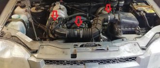
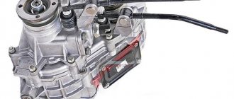
The device of the VAZ Niva transfer case
The transfer case is not present in all VAZ passenger cars, but only on cars with two drive axles. In the transmission, the transfer case (TC) is installed at the rear of the gearbox; a rear driveshaft is attached to its shank, which connects the transfer case to the rear axle. The front axle is also driven by the steering wheel; it is connected to the transfer case by a front driveshaft.
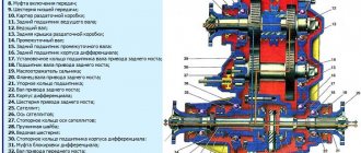
The reduction gear in the Republic of Kazakhstan is designed to obtain high torque, it is used to overcome difficult sections of the road, and helps to cope with off-road conditions. The VAZ Niva transfer case contains the following main parts:
- the body itself;
- front axle drive shaft;
- intermediate shaft;
- drive shaft;
- gears;
- bearings;
- differential housing;
- satellites;
- differential lock clutch;
- gear shift clutch;
- flanges (for connection to cardan shafts);
- oil seals;
- control levers.
Required Tools
First of all, prepare a large and small grinder (angle grinder), a drill (preferably not a battery-powered one), calipers, a roller, a hammer, a ruler, as well as protective equipment to prevent hot metal shavings from getting into your eyes while working with a grinder. All work should be carried out according to a certain scheme (you can see a drawing of the Niva 2121 transfer case subframe in the photo below).
So where to start? First you need to measure and process the base edge of the channel. After this, use a ruler to measure the required distances from it. Windows in the device must be cut out with a small and large grinder in the transverse and longitudinal direction, respectively. The length of the cut should not extend beyond 8 millimeters from the edge of the top flange of the structure. After the windows are cut out, the contours of the sidewalls should be processed and chamfered.
The angle of fastening to the spar and cross member of the device may have a free size, but it should not be less than the length of the mounting holes and the distance between them. If corners are not available, you can use a different scheme for fastening the part to the spar. It is important to maintain the height of the transfer case attachment to the subframe.
If this is a reinforced subframe, then metal corners are additionally welded under the mounting points of the box brackets. The latter are connected to the side parts of the channel. The oblong shaped holes go like a bolted connection.
Centering the transfer case VAZ-21213
| Centering the transfer case of VAZ-21213 Author ALER | GetPath(); Conference “Let's exchange experiences. Niva» NIVA-FAQ Equipment Transmission Transfer case |
The method of dynamic centering (balancing) of the VAZ-21213 transfer case is described here. The success of the operation (i.e., elimination of vibration and noise) depends not only on the transfer case itself, but also on the condition of the intermediate shaft and universal joints (and their crosspieces), since the complex of all of these components is balanced. It is recommended to carefully check and inject the splines and crosspieces of the universal joints. It also doesn't hurt to pre-balance the wheels.
Centering is performed by two people—let’s call the participants “driver” and “mechanic.” The car with the driver rises on a lift. Transfer case lever position: lock off, gear up. The gearbox engages fourth or fifth gear (see below about speed). The mechanic loosens the transfer case (4 nuts). The driver accelerates and, having reached the required speed, gives the go-ahead to the mechanic. Then the driver maintains speed until the mechanic commands. The mechanic, having received the signal, “on the fly” tightens the transfer case fastening and gives the command to complete the operation. That's all in general terms.
And the subtleties of the process are as follows.
1. The speed at which centering is performed may vary. One service recommended that I keep 60 km/h in fourth gear. This makes sense if the machine is used only in the city. In another - 90 km/h in fifth gear. I drive fast, so I prefer 100-110 km/h in fifth.
2. Loosening of the transfer case should be minimal, but sufficient for its mobility. The point of this subtlety is that the transfer case, when centered, is practically in the same horizontal plane as during operation.
3. Before centering, you need to place the transfer case supports so that the studs initially stand in the middle of the oval holes of the supports. This is possible due to the mobility of the splined joints of the cardan shafts. This installation provides maximum freedom for the transfer case to find the optimal position.
4. After gaining speed, the mechanic must push the transfer case several times from the side to the front, from the side to the back, or just from the side - to make it easier for it to find the optimum. But not forward or backward. This can be done, for example, with the handle of a hammer.
Advice - if centering is done at a service center in front of you, it is better not to get behind the wheel yourself, but to control the process from below, that is, to be, according to the role indicated at the beginning of the article, not a driver, but a mechanic or simply an “observer”.
Naturally, it is not at all necessary to have a lift. You can do this in a pit or just a flat area. The best result is obtained by exclusive centering - on stands under the suspension arms with the wheels removed. With this centering, the cardan shafts have the same angles as when the car is moving. Of course, the machine must be securely secured to avoid unnecessary risk. I know of a case where during centering they used stands made from stacks of bricks from which the car simply fell...
For the VAZ-2121, before dynamic centering, it is necessary to set the height of the transfer case by installing spacers under the transfer case supports. Gaskets are rectangular plates of different thicknesses. Their size corresponds to the dimensions of the transfer case supports, and instead of holes there are side cutouts so that the plates can be inserted under the supports without removing them from the studs. The use of washers instead of gaskets is strictly not recommended.
The method is well described in the Maintenance and Repair Manual. We can recommend the article in “Behind the Wheel”, which proposes an optical method (info provided by VadimM, TigerD and Vlad219i). At the end of the mentioned article there is a link to the article in ZR 1/98, where the method outlined in this article is briefly described, but in a more primitive form.
In the intermediate shaft of the VAZ-21213, a CV joint is used instead of a cardan, which allowed the plant to refuse to adjust the position of the transfer case in height. However, if there is noticeable deformation of the bottom in the area where the gearbox and/or transfer case is mounted, and also if the dynamic centering method does not give the desired result, you can try to adjust the position of the transfer case in height, and then repeat the dynamic centering.
I had to deal with another option for positioning the steering wheel - along the axis of the machine.
My 213 had the usual problem - the nut of the gearbox secondary shaft shank had come loose. I removed the boxes, went through the gearbox, then, when installing the boxes, I noticed that the studs on the CV joint of the drive shaft barely fit into the holes of the drive shaft flange when the gearbox was in the position closest to the gearbox. Everything came together due to the deformation of the elastic coupling.
I consulted with an authority on NIVAM in one service. He said approximately the following (he himself has a NIVA 2121): in his experience, the shaft with a CV joint is about 5 mm shorter than the shaft with a cardan joint, and the installation locations of the gearbox and gearbox on the 213th NIVA remained the same; axial stress during the assembly of the shaft and gearbox seems to be the cause of chronic problems with 5th gear and, in general, with the gearbox on many 213 NIVAHs.
To eliminate the described problem, this specialist modified the unit on many 213s, even completely new ones, as follows:
1) elongated studs were installed on the shaft instead of the standard ones; 2) between the ends of the drive shaft and the flange of the primary shaft of the RK (on the studs of the drive shaft), an insert with a thickness of about 5 mm is mounted (the insert is simply made from the drive gear flange of the rear axle by cutting off the excess on a lathe from its end part, on which there are exactly the necessary holes).
As a result, the unit operates without unnecessary axial stress.
This is also done on my car. Now everything is assembled much easier, positioning the control unit is also easier (however, now it is necessary to remember when assembling that if the control unit is excessively shifted towards the gearbox, the blower shaft can seem to “sag” and give off its own vibrations).
vlavuk, 03.08.01.
I haven't encountered a similar problem. And on both my Nivkas, and on the cars of other Nivkas that I observed during centering, the transfer case, after its installation, stood up so that the studs ended up in the middle of the oval holes of the brackets. But this is not a reason to deny the situation described above.
Centering the Niva transfer case horizontally
©Vladimir Tsebenko aka Fora-Vlad
To move the transfer case to the left, cut off part of the inner extension of the left bracket and put it on the right axle, adding a washer if necessary. The width of the sawn piece depends on the amount of displacement of the distributor (usually from 3 to 8 mm). When installing the transfer case, do not tighten the axle nuts (tighten them). After installation, check the gaps (minimum), you may have to add washers. If there are large inaccuracies in the fit, you will also have to saw off the outer overhang of the right bracket so that there is enough thread for the nut.
Message on www. : Maybe someone will find this useful. Yesterday I gave up on work and decided to help a friend with the ever-nagging transfer case, and then repeat it on my own. Upon inspection, it was discovered that the third engine mount was shifted to the left by 3 mm - I drilled holes in the cross member - it stood up easily, the transfer case was shifted to the right by 4 mm (this misalignment caused unregulated vibration) - I cut off the internal reach of the left bracket by 4 mm, put it on the right axle the cut off part (however, I had to add another thick washer). I added homemade shims under the box cross member to lower the front of the transfer case. The coaxiality of the transfer case and the box was controlled with a rod based on the distance between the end of the shank of the driven shaft of the transfer case and the end of the drive base of the coupling on one side and the other. When turning, the difference is no more than 0.5 mm maximum. This morning I walked along the embankment and enjoyed it - no vibrations up to 110! — there was no way to accelerate anymore. Good luck everyone
Message: Maybe someone will find this useful. If the displacement is small, then just turn the bracket over - they are not symmetrical. The difference is about 2 mm.
Answer:: =====And about the third engine mount it’s interesting, actually
. What prompted me to do this was that the engine mount under the spare tire was slightly bent (the other one was quite normal). Naturally, it was pulled by a third support, which I moved by boring holes in the cross member. Yes, an addition - before installing the cross member, I inserted rubber inserts from the sides of the third support (for example, from 41 Muscovite, the upper shock absorber rubber bands are suitable in diameter), which reduce the axial movement of the support.
Message: After removing the transfer case, before sawing, you need to measure the distance between the centers of the holes in the right and left brackets and compare with the distance between the studs in the floor. The difference (usually the distance between the studs is larger) is compensated by washers added to the axle. Don’t forget to do this, otherwise you’ll have to remove the transfer case twice - well, it’s a very vile task (my whole chest is covered in bruises - I don’t have a hole).
Addendum: Greetings. By alignment. I don’t have a 100% recipe, but I will tell you my algorithm. Preliminary adjustments of the transfer case led to the fact that it was deployed almost to its maximum, and even the third support was shifted. Fortunately, there is a lot of asphalt around, I drew my guts in natural size - in short, the total displacement (transfer case + gearbox) was about 7-8 mm (tenths are not important). I managed to move the transfer case by 6 mm (it didn’t work any more). When centering the transfer case, it stood almost along the body, and the distances between the end of the flange and the coupling fluctuated by 0.25 - 0.35 mm when turning. (the hole became almost straight). Centering in the vertical plane is incredibly simple. The transfer case must be horizontal (along the flanges). You bend down and look, aligning the line of the axes of the transfer case flanges and the lower edge of the threshold. Based on the result, you either place the plates under the transfer case or under the cross member of the box. I couldn’t find a ready-made one for the box - I made it myself. Yes, if the initial displacement of the transfer case is not very large (up to 4 mm), then it can be compensated by turning the brackets (though only in one direction) - they are not symmetrical.
Drawing by Vlad
Advice from AlBe l
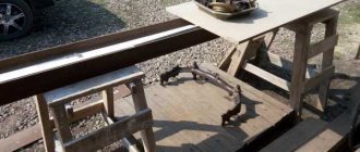
Last year, while changing the clutch at an open-air dacha, I encountered the same problem... How to remove and install the transfer case and gearbox with the least bruises on the chest (or better yet, without them at all). I used one technique as old as time - leverage. To be more specific, I took a board about three meters long, several scraps of a board about fifty centimeters long, 30 centimeters long and about 20-30 wide. I placed 2 posts from scraps under the distributor and under the threshold, so that the board would rest on these posts with a small gap. I unscrewed the last nut of the transfer case/box and after 20 millimeters the transfer case/box lay on the board (the board is placed under the expected center of gravity, of course). After that, I lifted the end of the board up and removed one piece of wood from under the threshold, then pressed the board down, hung out the transfer case/box, and removed one piece of wood from the column under the transfer case/box... and so on until the board lay on the ground, then on the board you drag the box/transfer case out from under the car. Install in reverse order. The effort at the end of the board that you raise/lower is minimal, a woman can handle it. The convenience is obvious, the time is minimal if you have a chainsaw ;-))… sticking the clutch housing into the bearing was not difficult at all, and almost perpendicular to the hole. It is advisable to carry out this procedure together - it’s more convenient... Good luck on the roads and less bruises on your chest 
Advice from Oleg I first tied it from above with a rope, pulling it across the positioned rod, then carefully lowered it on it. I also placed a hydraulic jack underneath, which turned out to be unnecessary insurance.
Advice from VadimM: Adding on the installation of the transfer case - two people installed it in the pit. One of the guys stood in the car above the tunnel and held the transfer case with a rope through the holes for the handles in the floor (you can rest it on some kind of crossbar). And at that time another guy was trying to bait her from below (a 40-minute lesson).
Get text
We install transfer case subframes on the Niva Comfort SUV: where is the protection attached?
It is mounted on the corners at the bottom of the device. As for the type of connection, it, similar to the two options listed above, is bolted. However, the holes in the body of the side parts of the device and the lower part of the corners are made according to the threaded principle. The protective sheet is part of the load-bearing structure, which forms a kind of box and gives the subframe greater strength. Accordingly, the box will be less vulnerable to various mechanical damage, which will have a positive effect on the Niva’s cross-country ability.
Other device mounting options
Installed part on the machine
Another way to secure the structure to the spar involves fixing it to the lower surface of the spar. For this purpose, holes are also made in the fastening points, but only in the upper and lower surfaces of the spar. In this case, you should not particularly find fault with the diameter of the fastening bolt, since there will be no impact on it. But it will be impossible to install additional silent blocks to dampen vibrations.
Another additional element that can be installed on the structure is a special elastic support for the box. It is believed that it allows you to better set the position of the box relative to the gearbox. But in some cases they can do without it. It all depends on the wishes of the owner.
Some car enthusiasts cover this entire structure with a sheet of metal, which additionally protects the transfer case from contamination and possible damage when driving off-road.
The disadvantage of the subframe installed on the Niva is the reduction in ground clearance in the transfer case area.
Additional holes
An additional window is cut under the drain plug to drain the oil. You can drill holes in any place convenient for you, without bothering with the accuracy of the markings. Car enthusiasts also make technological windows to drain the water formed between the sidewalls of the channel and the dirt that gets there. The protection is enhanced by corners that are attached to the box support and the frontal part of the entire device. This design will protect the transfer case from all kinds of impacts on stumps, ditches and other obstacles that can lead to deformation of the subframe.
How can you improve your device for extreme driving?
In this case, you can change the profile of the sidewalls of the device, which will make it flatter and more durable. The corners are welded not only to the transfer case brackets, but also to the side shelves of the channel. They are also attached inside the last element. At the end you should have a frame of four corners. This design makes it possible to cut the sidewalls of the channel to fit the corner flange. As a result, the height of the subframe will be reduced by 50%, and the strength will double.
What dangers can await a motorist while driving?
As practice shows, even such a device as a subframe does not guarantee 100% protection for the transfer case and other components of the car while driving off-road. Therefore, if you often operate the Niva in rural areas, where there is a danger of “picking up” a stump or some other object that is difficult to notice in uncut grass, install the special protection on the subframe that we talked about in the previous paragraph. Then the risk of transfer case deformation will be reduced to zero. If there is no such protection, both the subframe and the box itself will deteriorate.
So, we found out how to make a transfer case subframe for a Niva with our own hands. Whether you need it or not - decide for yourself.