Today, every car, regardless of type, is equipped with special protection for all electrical systems. This protection is called a fuse. They are installed so that in the event of a short circuit or malfunction, the system can turn off via a fuse, thereby protecting itself from breakdown. Fuses are used for every electrical circuit, from a small light bulb to an engine's ignition system. More important engine systems are equipped with special relays, they protect various pumps, electric motors and other powerful sources of electricity consumption.
The fuse is a small structure consisting of a plastic casing with a fusible element inside. If a short circuit occurs, the thin contact melts under the influence of current, which interrupts the electric current. The simplest electrical fuse is a thin copper wire inserted into a circuit. If the upper limit of the supplied current increases, the contact begins to melt and interrupts the flow of electricity. Here there is a description of all fuses and relays for VAZ 2113, 2114, 2115 models of injection and carburetor types, old and new models.
Interpretation of fuses and relays of injection models
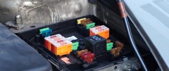
The main electrical fuse module 2114-3722010-60 is located under the front engine compartment. This arrangement allows for quick access to all electrical systems of the car.
Block location
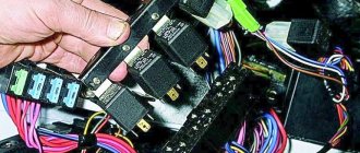
Please note that the location of the electrical fuse module may depend on the type of equipment and year of manufacture of the vehicle. As a rule, this is the upper right part of the engine compartment, under the front windshield. The mounting block is made of plastic in the form of a rectangular box. To protect against accidental opening, the box is equipped with special latches. To open the module, you need to snap off the two protective brackets and lift the top plastic protection. Under the cover are all the main control relays and electrical fuses of the vehicle.
To quickly remove the fuse, special plastic pliers are located on the plastic protection cover. With their help, you can very easily get any element. You need to grab the top edge of the plastic case with pliers and carefully lift the element.
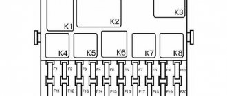
For the convenience of the user, on the top plastic cover there is a complete diagram, made in the form of a schematic image, which shows all the electrical fuses and relays indicating the current strength (A).
Fuse and relay diagram for injection models
Table 1. Explanation of fuses and relays 2114-3722010-60
| № | Current, A | Explanation of fuses |
| F1 | 10 | Rear fog lights, rear fog light indicator lamp |
| F2 | 10 | Turn signals and turn signal breaker relay. Alarm system. Hazard warning lamp |
| F3 | 7,5 | Interior and luggage compartment lighting systems (interior lamp, luggage compartment lamp, ignition key illumination). Brake brake lamp, on-board computer backlight lamp. Engine control lamp |
| F4 | 20 | Rear window heating control. Portable lamp connection socket |
| F5 | 20 | Relay for monitoring and turning on the sound signal. Cooling system engine switch fuse and relay |
| F6 | 30 | Control and relay switching on electric windows |
| F7 | 30 | Electric motor control - heating system, interior heater, windshield washers, headlight cleaners. Interior cigarette lighter, glove box lamp. Turn on the heated rear window. |
| F8 | 7,5 | Turning on the right fog lamp |
| F9 | 7,5 | Turning on the left fog light |
| F10 | 7,5 | Side light for the left side body, indicator light for turning on the side lights (on the display), lamps for illuminating the license plate and engine compartment, illumination lamp for switches, cigarette lighter, heater control levers. Instrument lighting switch. |
| F11 | 7,5 | Right side body marker light |
| F12 | 7,5 | Front right low beam headlight |
| F13 | 7,5 | Front left low beam headlight |
| F14 | 7,5 | Front left high beam headlight. Light indicator lamp. |
| F15 | 7,5 | Front right high beam lamp. |
| F16 | 15 | Body turn signals, relay-breaker for turn signals and hazard warning lights. Control relay and reverse lamps, indicator lamps for the on-board instrument control system, lamps for oil pressure, handbrake activation, brake fluid level, battery charge. On-board computer, engine generator winding. |
| F17-F20 | Spares | |
| № | Relay circuit | |
| K1 | Headlight cleaners | |
| K2 | Turn signals and hazard warning lights | |
| K3 | Windshield wiper | |
| K4 | Monitoring the serviceability of brake light lamps and side lamps | |
| K5 | Window lifters | |
| K6 | Sound signal | |
| K7 | Heated rear window | |
| K8 | High beam headlights | |
| K9 | Low beam headlights | |
Why do you need heated seats?
This is an important and necessary thing in your car, especially at a time when it is bitterly cold outside. If you very often get into the cabin of a car that has been standing in the cold for a long time, it is not only unpleasant, but also dangerous to the health of the driver and passengers. But at the same time, overheating of the seats also promises problems for those sitting on them, and in some cases for the car.
You can find a lot of information about both the benefits of heating and its inappropriateness. Let's try to understand this information together. Long trips with the heaters on can have a negative impact on men and women. Therefore, you need to be able to use this function correctly and in a timely manner. Sitting in a cabin with leather seats in winter can cause problems for drivers of both sexes, in the form of cystitis or prostatitis.
There are certain, developed and time-tested rules for using heating:
- Do not allow the seats to become overheated;
- In a cold car interior, you should turn on the heating system, but do not sit on them for some time;
- After warming up, the system must be turned off, further heating must be carried out using a heater;
- There is no need to stay in the salon for a long time in warm clothes.
Decoding fuses and relays of block 2114-3722010-18
VAZ-2114, 2115, 2113 cars of the first models with a carburetor have certain differences in the fuse module.
Old style block fuse and relay diagram
Table 2. Decoding of fuses and relays of block 2114-3722010-18
| № | Current, A | Explanation of fuses |
| F9 | 7,5 | Right rear fog lamp |
| F8 | 7,5 | Left rear fog lamp |
| F1 | 10 | Front headlight cleaners at the moment of switching on, wiper contacts, headlight washer switch valve, headlight wiper switch relay contacts |
| F7 | 30 | Front headlight wipers during operation, winding of the relay for turning on the wipers, fuse for the interior heater, windshield washer, gearbox and timing controller for the rear window wiper, valves for turning on the front and rear washer, relay (winding) for turning on the engine cooling system, relay for turning on the rear window heating, glove box lighting, rear window heating control lamp |
| F16 | 15 | Turn signal indicators and activation of hazard warning lights in turn mode, indicator control lamp, reversing lights, gearbox and relay for activation of windshield washers, generator winding (at startup), control lamps for brake fluid, oil pressure, carburetor flap, hand brake. "STOP" display lamp, voltmeter and coolant temperature indicator |
| F3 | 10 | Interior lighting and rear brake light |
| F6 | 30 | Power windows, power windows on/off relay |
| F10 | 7,5 | License plate lights, engine compartment lamp, warning light on the dashboard (exterior lighting), instrument panel lights, cigarette lighter light, heating lever lights |
| F5 | 20 | Relay for turning on the cooling system fan (electric motor), sound signal. |
| F10 | 7,5 | Left front marker light Left rear marker light |
| F11 | 7,5 | Right front headlight, right rear |
| F2 | 10 | Hazard warning lamp, turn signals and hazard warning relay. |
| F4 | 20 | Rear heated glass, heating on, portable socket, cigarette lighter in the cabin |
| F15 | 7,5 | Front right high beam |
| F14 | 7,5 | Front left high beam Light switch |
| F13 | 7,5 | Left low beam |
| F12 | 7,5 | Right low beam |
| № | Relay circuit | |
| K1 | Headlight washers | |
| K2 | Hazard and turn signals | |
| K3 | Windshield wipers | |
| K4 | Monitoring the health of lamps | |
| K5 | Windows | |
| K6 | Sound signal | |
| K7 | Heated rear window | |
| K8 | High beam headlights | |
| K9 | Low beam headlights | |
General design of the generator set
- Covers made of aluminum alloys. They contain special sockets into which bearings are pressed. On the back cover there is a terminal for connecting to the battery and a connector (“male”) for connecting to the excitation winding. There is also a capacitor attached to the back cover. It helps suppress radio interference. The brush assembly is mounted in the same housing with the VAZ 2114 voltage regulator. The generator operates due to the fact that an emf created by the rotating magnetic field of the rotor is induced in the stator winding.
- The stator is made of plates made of special grades of transformer steel. It has special grooves into which the power windings are placed. Each has a terminal for connecting to a rectifier. The covers are bolted to the stator. The field winding is located on the rotor. It is connected to copper rings. They are on the shaft. A drive pulley is installed at the front, and there is a keyway for it on the rotor.
- The diode block is attached to the back cover from the inside. It consists of nine semiconductors - six main and three additional. To ensure high-quality cooling of semiconductors, aluminum alloy plates are used. And on the front part next to the drive pulley there is an impeller.
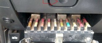
Starter, ignition, rear fog lamp relay
In order to carry out quick checks and repairs, the ignition system relay is installed under the front dashboard of the car, behind the hood release handle. It is located just below the central dashboard. The module is closed with a plastic plug, which must be opened slightly to test for functionality.
Starter, ignition, rear fog lamp relay
Next to the indicated relay, there is a similar one for the rear fog lights and the starter.
The main task of the relay when igniting is to reduce the applied load to the contacts. When the engine starts, the relay turns off some electrical circuits in the vehicle system. The system is used not only in injection, but also in carburetor engines.
In the event of a malfunction or malfunction in the ignition system, it is necessary to monitor the operation of the relay. For this purpose, open the box and carefully remove the desired element. It is attached using contacts to special grooves. The first thing to do is look at the oxidation of the contacts, if necessary, clean them with a soft cloth or treat them with a special liquid.
To check functionality, you need to use a regular multimeter. We connect to incoming connections and check the numbers. If there is no short circuit when current is applied, it means the element is not working. Replacement is carried out in a similar manner. It is necessary to use a standard element with the number of amperes indicated on the housing.
Recommendations for care and maintenance
- Buy original fuses. Domestic or foreign, it doesn’t matter;
- Install strictly in accordance with amperage ratings. Unacceptable with lower or higher current strength. In the first case, this will lead to damage to the module, in the second - to breakdown of the unit, which is attached to the fuse;
- Carefully check the quality of fixation of terminals and limit switches on the board. If loose, tighten and press with pliers. A spark can cause a fire and melting occurs;
- If moisture gets in or condensation forms inside the mounting block, remove the cover, dry it, and if necessary, blow it with a stream of compressed air.
Carry out preventive and diagnostic work in the fuse box with the battery terminals removed in order to prevent a short circuit in the circuit.
The average service life of fuses is 40 – 60 thousand km. The service life of foreign analogues is 10–15% longer. Before replacing, read the instructions and get advice from service station specialists.
Sources
- zapchasti.expert/predoxraniteli/predoxraniteli-vaz-2115.html
- avtoblokrele.ru/vaz/blok-predohranitelej-vaz-2113-2114-2115.html
- drive2.ru/l/5419303/
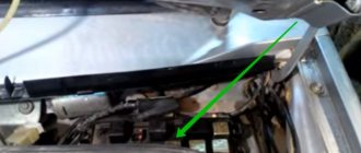
Front fog lamp relay
Front fog lights are not standard equipment on the model and are equipped depending on the configuration. The relay itself (if there are fog lights) is located in the engine compartment on the left mudguard.
Front fog lamp relay
Important! To access the relay, you must remove the battery! Without performing this manipulation, it will be difficult to remove and check its functionality.
Replacing a faulty element is very simple. You need to take a Phillips screwdriver (with a short handle), unscrew the bolt securing the relay to the car body, and check the element for malfunction. If it fails, we buy a new one and put everything in the reverse order.
Replacing fuses on a VAZ 2115
Preparatory stage:
- Driver, head at “10”;
- Flat head screwdriver;
- A set of new modules;
- Plastic pliers for removing the relay block;
- Rags, additional lighting as needed.
Sequencing:
- We turn off the engine, open the hood, remove the terminals from the battery;
- On the left side, closer to the windshield, there is a mounting block. Unscrew the two bolts around the perimeter;
- We disconnect two blocks with wires, remove the power supply assembly;
- We carry out troubleshooting and check the serviceability of all modules.
You can do this in two ways:
- Visually: checking each module for the integrity of the melting element;
- Using a multimeter: measuring the resistance at the end switches of the module without dismantling it.
Each method is applicable and effective.
After replacing the faulty fuses, we assemble the structure in the reverse order.
Some motorists practice the second method: without dismantling the mounting block. We remove the fuses one by one, check them for integrity, and replace them with new ones as necessary.
Unmute
If you notice that a unit in your car has suddenly stopped working, do not rush to dismantle it and replace it with a new one. First of all, inspect the mounting block, check the modules for integrity. Most likely some kind of fuse has blown.
Only after replacing the module does not help eliminate the problem, proceed to diagnosing the equipment and checking the integrity of the electrical supply circuit.
Signs of regulator malfunction
Sometimes during the operation of a car it happens that the stabilizer fails. Signs of this may include frequent fluctuations and sudden surges in voltage in the vehicle network, problems with electrical appliances and rapid discharge of the battery. If you notice one or more of the above signs, then the relay regulator of the VAZ 2114 generator should be tested using a multimeter.
You can do this as follows:
- Set the tester to measure DC voltage with a limit of 20 volts.
- Measure the voltage readings at the battery terminals with the engine turned off (the result should be from 12.5 to 13 volts).
- Start the engine and measure the voltage at the terminals again (now it should be between 14 and 14.5 volts).
- Without turning off the engine, turn on the high beam, heater and heated glass (other powerful consumers can also be used). Measure the voltage on the battery a third time. The voltage readings should be in the range of 13.2-13.9 volts - this will mean that the stabilizer is fixed. Otherwise, the device will have to be dismantled and replaced.
Traveling in a car with a faulty generator regulator is not profitable and even unsafe, as this can lead to increased fuel consumption, breakdowns in the on-board network, and even a car fire.
You can check the correct operation of the regulator without using a multimeter, with the device removed. To do this, you need to connect its “ground” terminal to the negative of the battery, and connect contacts B and C to the positive. After this, you should take a 3-watt car lamp and connect it to the graphite brushes of the regulator. If the latter is working properly, the lamp will light up.
In some cases, you can go even further and check the trigger threshold. To do this, the regulator should be connected as mentioned above, but between its positive terminals and the plus of the battery, connect a pair of AA batteries in parallel in order to increase the voltage in the network to 16 volts. If the regulator is working correctly, it will interrupt the power supply and the light bulb connected to its brushes will not light up.
The car won't start - 5 most common reasons
Imagine getting into your car in the morning to go to work. And suddenly the car won't start. This situation can confuse many drivers. Why did this happen if everything was fine yesterday?
We've collected the 5 most common reasons why a car won't start and told you how to diagnose and fix the problem.
Replacing the ignition relay for a VAZ 2107
relay is used to turn on the power supply for the accounting ignition system on carburetor non-injection modifications of the “Seven”. If this part becomes a cause of machine malfunction, it does not have to be replaced. You can localize the problem without the help of others, without resorting to the services of specialized 100. List of forums autolada.ru - Classic - and where in 2107 is turn signal relay , one on. For this purpose, it will be necessary at the cinema hall level not to know where the relay and how to change it correctly.
READ Renault Simbol Rear Wheel Bearing Replacement
Candles
Another reason is spark plugs filled with gasoline, whose job is to ignite the fuel. If the elements are installed a long time ago, they gradually become dirty. Each automaker specifies the intervals for checking and replacing spark plugs in the maintenance schedule. In addition, the necessary information is indicated in the service book or in the vehicle’s operating manual.
When the driver tries repeatedly and unsuccessfully to start the car, the spark plugs become heavily flooded with gasoline. After that they definitely won't work anymore. To correct the situation, unscrew and dry them.
Candles can also be filled on a carburetor engine. But the described situation is especially relevant for modern cars with electronic injection, when the driver unknowingly begins to repeatedly press the gas pedal, which in this case only causes harm.
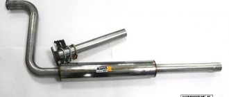
Alternator Removal Tools
A bracket is attached to the engine block (approximately in the middle). The generator housing is secured to the bracket on the block using a special strip. Thanks to it, it becomes possible to adjust the belt tension. To remove the generator, you will need the following tool:
- Wrenches (preferably box and open-end) with sizes “10”, “13”, “17”, “19”.
- Some vehicles may require a "15" socket.
- A small pry bar or short piece of pipe.
Reviews
| № | Positive |
| 1. | Ivan , 39 years old, Sverdlovsk: satisfied with the standard heating, the car is in its second year, no complaints. |
| 2. | Vladlen , 41 years old, Samara: bought a Lada Vesta secondhand, got it from the previous owner in good condition. All mechanisms are in good working order, including heating, heater, air conditioning. |
| 3. | Peter , 45 years old, Krasnodar: in three years of active use of the car, I replaced the heating fuse (FF33) once. I am pleased with the build quality of the domestic car. |
| 4. | Gennady , 38 years old, Rostov-on-Don: the “native” seat heating works effectively, without any comments. It heats up in just under a minute, the heating area is the outer perimeter of the seat. |
| 5. | Dmitry , 41 years old, Kursk: the temperature heats up quickly, consumes little energy. As a drawback, I would like to note the insufficient heat conduction when the covers are on. |
| 6. | Negative |
| 7. | Victor , 35 years old, Uralsk: after the first winter, the heated seats stopped working, so he contacted a service station. Based on the diagnostic results, it turned out that the wiring had burned out. They replaced it with a new one under warranty. For a car of this class, the quality should be higher. |
| 8. | Fedor , 42 years old, Moscow: my heating is unstable. I checked the fuse, it is working, apparently the reason is in the heating element itself under the casing. |
| 9. | Kirill , 32 years old, St. Petersburg: in general, I’m happy with the Lada Vesta car, breakdowns happen, I try to quickly fix them. Of course, domestic transport is far from its foreign counterparts. |
| 10. | Vasily , 42 years old, Pskov: dissatisfied with the build quality of the Lada Vesta, since the heated seats stopped working in the first year of “life”. In the workshop I discovered the cause - a defective temperature sensor. |
Brush mechanism failures
Faults can be divided into two types: breakdown of brushes or voltage regulator. Replacement of brushes and relay regulator is carried out without dismantling the generator. Diagnostics can also be done using improvised means - a pair of AA batteries, a battery, a light bulb or a tester. The cost of the brush assembly is quite low, so you don’t have to check it, but immediately install a new one and forget about the problems. But if you get excited about the idea, then diagnostics are performed as follows:
- Connect power to the voltage regulator.
- Connect the incandescent lamp to the brushes.
- At a voltage of 12-14 Volts, the lamp lights up.
- When increased to 15-16 Volts, it goes out.
This is normal operation of the regulator. If the lamp behaves differently during diagnostics, we can talk about a breakdown of the relay regulator. It is also worth mentioning the signs of worn brushes:
- There is a decrease in voltage in the on-board network.
- The battery is not charging.
- Voltage surges are observed.
After removing the brushes, visually assess their condition - if the length is less than half a centimeter, then you can safely throw them away. Also pay attention to how the brushes of the VAZ 2114 generator move in the grooves - if there are jams, it is better to install new ones or drop a little clean oil. Be sure to evaluate the condition of the slip rings on the rotor; sometimes they need to be ground. After installing the new brushes, it takes a few minutes for them to start working properly.
Basic principles of heating operation
The basis of any heating system for interior seats is a heating network, powered, like other electrical appliances, from the vehicle’s on-board network. Being enclosed in a flexible molding, it is built into the cushion and back (without a headrest) of the seat, although if you wish, you can equip a car without this option with heating - simply by purchasing a seat cover that connects to the cigarette lighter.
In order not to melt the filling inside the seat, the contact network, which transfers heat to the outside, is additionally placed in a safe coating that flexibly follows the topography of the chair.
The simplest connection diagram involves just one serial heating circuit with a simple thermal relay that turns the heating
, depending on the temperature preset by the factory.
More complex options allow for the presence of not only a temperature sensor, but also a manual regulator that allows you to set the desired degree of heating - thanks to this, instead of aimlessly increasing the temperature, the chair will maintain the same indicator until it turns off.
There are other types of heating options:
- a timer that turns the heating on and off at certain intervals;
- separate choice of temperature for the cushion and back of the chair;
- memory of several selected temperature modes, activated with one click;
- the presence in the chair of several independent circuits with varying degrees of heating.
As practice shows, the more complex the system, the more weak points it has that can fail, starting with the fuse box and ending with oxidation or broken contacts - if the breakdown lies inside the seat, the repair will take a lot of time and require good skill.
How it works?
The main element of such a system is a heating element powered by the on-board network. It is placed in an elastic panel and built into the cushion and backrests of the front seats. Such systems come in two types, one of which is built into the cushions, and the second is made in the form of seat covers. Despite these differences, the principle of their operation is almost the same.
To avoid direct contact with the seat upholstery, the heating elements are covered with a special coating, which makes it easy to copy the contours of the pillows. There are designs with one heating element and with two, but of different power. The heaters are connected to the machine's on-board network via a control unit. Some models have the ability to set the desired temperature.
A temperature sensor is installed in the heater installation area; it monitors the heating temperature and, when the desired value is reached, turns off the power. The system may also have another function that will automatically maintain the heating parameters set by the driver for a long time. Another type of heater can be controlled using a built-in timer.
Also, built-in devices with two heating elements can support a quick warm-up function, after which they automatically switch to lower power and less heating. Some models may have several such modes; they can be selected individually for each seat.
Specifications
Brief description of the technical characteristics of the generator:
- The rotor winding (excitation) is powered by a voltage whose value is in the range of 13.2 – 14.7 Volts.
- Under a load of 10 kg, the belt sag (over a long section) does not exceed 0.8 cm.
- The generator on the VAZ 2114 (its price in stores is about 4,000 - 4,500 rubles) is capable of delivering a current of up to 80 A to the network.
The unit is located on the left side, the drive is carried out using a poly-V-belt from a pulley on the crankshaft of the car engine.