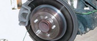
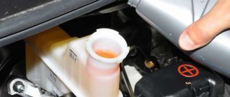
Many drivers, and even people who do not have a car, know that a passenger car differs in many ways from a truck. We are talking not only about the dimensions, weight of the car or the size of the wheels; of course, we are talking about the technical aspect. In modern trucks, many things are arranged differently; even the brake system here is pneumatic, which is fundamentally different from the disc brakes typical of passenger cars. It is about the characteristics, features and differences of this type of system that we will talk about, because your safety on the road depends on the understanding and serviceability of the brakes, as well as their internal components, especially for drivers of heavy trucks.
Operating principle of the pneumatic braking system
Let's start with the fact that the operation of the pneumatic braking system is based on the principle of using the power of compressed air, which is concentrated in special cylinders and pumped using a compressor. This distinguishes it from all other types of braking units and this is its main feature.
If we describe the operation of this braking system quite simply, then everything looks like this. A certain amount of air is supplied under pressure from special cylinders to the system compressor. Next, after the driver presses the brake pedal, the force is transferred to the brake valve, which creates pressure in the brake chambers.
The cameras themselves are activated thanks to the lever of the brake mechanism, which, in principle, allows the braking process to be carried out. As soon as the driver releases the brake pedal, the lever will weaken, stop working and the stopping process will stop.
Air brakes
The principle of movement of any vehicle with an internal combustion engine is based on the conversion of thermal energy into mechanical energy. To transmit it, the machine design provides a complex system of components and parts. The final factor that provides movement is traction. It is formed due to the displacement of tires along the road surface. The speed of movement depends on the power of the power unit and the amount of traction. The braking system ensures that the vehicle stops. The pads are pressed against the surface of the drum, during which their temperature rises. Based on this information, it turns out that the motor converts thermal energy into movement. Brakes, on the contrary, convert motion energy into heat. It, in turn, dissipates through the surface of the drums into the atmosphere.
Types of braking systems
If the power unit has a capacity of 250 hp. accelerates a vehicle to 100 km/h in one minute, then in an unexpected situation it takes only 6 seconds to stop. In other words, the braking system must create a force equal to 2000 hp. With. In this case, the energy required to stop is proportional to the mass of the car and the square of its speed. To solve these problems on modern machines, a hydraulic or pneumatic brake system is installed. The first option, as a rule, is used in the design of passenger cars only. This is due to significant disadvantages, one of which is the fact that the oil may suddenly run out. The pneumatic system does not have this drawback, which makes it as safe as possible. Even with a small leak, the brakes will still work. Let's take a closer look at its design.
Detailed consideration of the issue
If we delve a little deeper into the principle of operation of this unit, everything will be somewhat more interesting. The brake system pumps air into the cylinders while the engine is running (the vehicle is moving), and the brake pedal must be released. Next, air under pressure rushes to the brake valve, and if a trailer is attached to the truck, then oxygen from the valve is also transferred through the upper section to the trailer cylinders, thus forming a continuous contact.
As soon as the driver presses the brake pedal, the upper section must suddenly close, accordingly, the contact of the two components is interrupted, and the brake valve opens. Next, after opening the tap, air should enter the pneumatic chambers, and the car and the trailer begin braking. The important point here is that the upper section is responsible for bringing the trailer's braking system into operation.
The lower section of the brake system is responsible for stopping the tractor, which is the truck itself. The action here is absolutely similar to what was described in the previous paragraph, but let’s look at the mechanism of action even more closely.
After air enters the pneumatic chambers, it begins to push through the diaphragm. This, in turn, compresses the spring built inside. Next, the pressure from the air shocks pushes the pusher, and all the force is transferred to the release cam lever. Then, the cam, or rather the roller mounted on it, begins to turn and spreads the brake pads to the sides, thus the braking system forces the car to stop. By releasing the brake pedal, the process is reversed, the built-in springs return to their places, and excess air escapes.
Home / Train driving technologies
Air brakes
Operating principle and features of pneumatic brakes
When the train moves, the locomotive crew constantly regulates traction force and speed. The need for this is caused by the continuous change in the profile and plan of the path, and therefore the resistance to movement, as well as different levels of permissible speeds and the need to stop at separate points. It is impossible to implement such a mode using only the traction force and the force of resistance to movement; this requires the braking force of the train, created as needed, and changed by the driver. It is with its help that the train is stopped and its speed reduced by absorbing the kinetic energy of a moving train.
Air brakes are the main ones on railways. When used correctly, they are reliable and safe. The principle of operation of pneumatic brakes is based on the effect of sliding friction between two materials, in which a frictional force arises, which is directed in the direction opposite to the direction of movement. As a rule, the friction surfaces are the brake pad and the rolling surface of the wheelset. With the introduction of disc brakes, brake linings and brake discs have become objects of friction. When braking, the kinetic energy of the train, due to the resulting friction, is converted into thermal energy, and is also partially spent on the destruction (abrasion) of the brake elements. Due to the fact that the friction coefficient depends significantly on the speed of movement and has an inverse relationship, the braking force during pneumatic braking decreases with increasing speed. Thus, the pneumatic braking mode is an unstable system - i.e. There is a certain speed value, if not exceeded, then applying the brakes will cause the train to stop. And this, as a rule, suits everyone - after all, will we ever need to stop? But this same feature can also play a cruel joke - at high speeds or on steep descents, the braking effect may not be enough and the speed will begin to increase, which will entail an even greater reduction in the braking effect. In such cases, it is necessary to immediately increase the braking force by increasing the discharge of the brake line, up to and including emergency braking. A delay in making a decision may result in the speed increasing so much that even achieving 100% braking force is not enough. The only reassurance is that this is possible only in exceptional cases - insufficient efficiency of the train brakes for a given slope.
Another feature of air brakes is that they can wear out. The fact is that both power supply and control of the train’s pneumatic brakes occur through one channel - the brake line. In this regard, completely opposite requirements arise. From the point of view of power supply and charging of brake devices, the brake line must be of a sufficiently large diameter so as not to impede the air flow for the rapid delivery of compressed air to consumers (TC, ZR). But from a control point of view, on the contrary, it is necessary to reduce the volume of the brake line, because it is in this case that its inertia decreases, the processes of pressure changes occur faster and more clearly. From a control point of view, it is also necessary to minimize the number of branches from the brake line in order to increase the speed of signal transmission. In the presence of these contradictions, this braking system makes it difficult to control long trains and maintain high speeds in freight trains, and therefore it is one of the limiting factors in the development of railways.
Adjusting braking force and limiting when using air brakes
The braking force of pneumatic brakes can only be adjusted within a limited range. The following types of braking are distinguished: stage braking, full service braking and emergency braking. The last two are used only when particularly necessary. The braking levels, in turn, are determined by the amount of discharge in the brake line. For the first stage, the discharge value is 0.5-0.6 Atm, for the second 0.8-0.9 Atm, and for the third 1.0-1.2 Atm. During the braking process, it is possible to increase the braking force by increasing the discharge of the brake line, but by an amount of at least 0.3 Atm, which is due to the sensitivity of both the driver's equalizing piston and the sensitivity of the air distributors. If the discharge depth is 1.5-1.7 Atm from the initial charging pressure, then the brakes can be released only after stopping. This requirement is due to several reasons - firstly, after such braking, the braking system is significantly depleted and there is a danger of driving for a long time without the ability to apply high-quality braking. Secondly, with such a magnitude of discharge, a rather large braking force arises and during release there is a danger of an increase in longitudinal reactions, which can lead to a train break. In some cases, it is possible to release the brakes after the pressure in the brake line drops below 3.5 Atm. To do this, it is necessary that the front profile has a rise or platform of sufficient length, at which there will be no increase in speed. It is also not recommended to release the brakes in winter after applying braking stages with a large discharge of the line and at low speeds. This is due to the fact that in this case a rather intense deceleration of the train occurs, and given the low temperatures, a slow release of the brakes in the rear part of the train may occur. All this will lead to large longitudinal reactions and the danger of the train bursting.
When the brakes are operating in flat mode, when the pressure in the brake line increases by 0.3 atm. the brakes are completely released. In connection with this, there is a requirement for the operator’s crane that the pressure in the equalization tank must not increase when it is in the overlap position.
Stepped release of pneumatic brakes is possible only when driving a train in which the air distributors are set to mountain mode. In this case, it is possible to slightly reduce the braking force by increasing the pressure in the brake line. Complete release of the train brakes occurs when the pressure in the brake line increases to a level of 0.2 atm. below the pre-brake level or even higher.
Features of operation of pneumatic brakes in winter conditions
The winter period is unfavorable both for the braking system as a whole and for brake control. The main factors during this period are low temperatures and snowfalls. In rare cases, such a natural phenomenon as “ice rain” appears. With the latter, everything is quite simple - when such precipitation passes, icing occurs on the surface of the rails, which leads to a sharp decrease in the adhesion of the wheelset to the rail and the danger of such a phenomenon as skidding. In addition, icing of the brake system of cars may occur, which also leads to deterioration of the brakes.
Unlike “freezing rain,” snowfall even “more effectively” worsens the performance of braking equipment. Firstly, it is lighter and can rise as a result of turbulence from the movement of the train. Secondly, in open areas, path changes occur, which as a result lead to a decrease in traction. When applying the brakes, the brake pads heat up, and in snowy conditions, snow settles well on the warm surface, which in turn melts into ice, forming an ice crust on the friction surface of the brake pad. During subsequent braking, it takes time for this ice crust to melt and for contact between the brake pad and the wheel tread to appear. In addition, wet snow also effectively sticks to the brake linkage, impairing its performance.
Low temperatures significantly impair brake performance. At low temperatures, atmospheric moisture condenses in the brake equipment in the form of frost and ice plugs. This circumstance alone can lead to poor performance or complete brake failure. To combat this phenomenon, it is necessary to provide high-quality drying of the compressed air on the locomotive, regular and, most importantly, correct blowing of the lines and brake units of the locomotive. If signs of freezing are detected, it is necessary to immediately take measures to stop the train and eliminate the malfunction. At low temperatures, lubricants thicken, which in turn leads to deterioration in the performance of various components in which pistons or spools are used. These include some types of air distributors, brake cylinders, switch valves, etc. For this reason, the response time of the brake system increases when braking begins and when the brakes are released. In addition, due to the freezing of the spool to the mirror in the air distributor 292, when the brake line is discharged by the amount of service braking, it can “break down” into the emergency braking position. Another feature of low temperatures is that the metal becomes more brittle and withstands less tensile strength, this is especially true for automatic couplers. Taking into account the fact that braking processes occur much slower in frosty weather, large longitudinal-dynamic reactions occur in the train, and taking into account the reduced strength of the metal of automatic couplers, control of pneumatic brakes becomes a more complex process that does not allow for risk.
Calculations of braking modes
In braking calculations, the total braking distance is calculated as the sum of two components: the preparatory braking distance Sp, which depends on the speed of the train at the moment of braking and the time the brakes are prepared for action, and the actual Sd. The time it takes to prepare the brakes for action is determined by the time the brake wave propagates along the line, fills the brake cylinders and presses the brake pads. When determining the time for preparing the brakes for action, the slow real process of increasing air pressure in the brake cylinder is conventionally replaced with an instantaneous jump to the maximum calculated value. It is assumed that during the preparatory time the brakes do not operate and the train passes the pre-braking preparatory track. After this time, the brakes are instantly applied and the train travels the rest of the braking distance with full pressure on the brake pads. Such a replacement of the actual braking process by a conditional one is legal if the braking distances traversed by the train with real and conditional filling of the brake cylinders are equal. Taking this into account, the Traction Calculation Rules recommend calculation formulas for determining the time for preparing the brakes for action depending on the type of train (freight, passenger, single locomotive), number of axles, slope, calculated braking coefficient and calculated coefficient of friction of the brake pads.
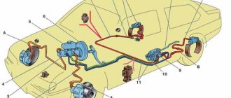
Main components of an air brake system
The brake system under discussion is divided into several main components, thanks to which the entire assembly can function properly. Naturally, the list of mechanisms below is incomplete, but, as already mentioned, it will contain the most important things:
- Control drive - this brake system implies the presence of pneumatic drive elements by the control drive. With the help of these parts, automatic or intentional regulation of some parts of the energy drive is carried out, which we will discuss in the next paragraph.
- Energy drive - this mechanism of the pneumatic brake system is a set of elements (parts) due to which the control drive is enriched with pressurized air. Thus, the mechanisms presented in the first two paragraphs (this and the previous one), so to speak, complement each other.
- The brake is the most “central” device! It is here, in this mechanism, that all the forces that resist further movement of the machine in any direction are concentrated. There are several different types of brake:
- Friction - a stopping value appears during the contact of two parts of a vehicle that are moving towards each other.
- Electric - the same frictional forces arise under the influence of an electromagnetic field, but the objects do not touch.
- Hydraulic - here again there are two objects moving towards each other, but interaction occurs when the pressure in the liquid between them increases.
- Motor - the braking value increases as a result of the fact that the engine artificially increases the braking effect, while the kinetics is transmitted directly to the wheels of the car.
- Compressor - many people have come across a similar device in everyday situations not related to cars. Essentially, it is an air pump that is responsible for ensuring that the brake system receives the required amount of air, as well as regulating the pressure within the system. This mechanism contains a pressure regulator, which is charged with the mission of monitoring and controlling the supply of compressed oxygen to the compressor, so that the values fluctuate within the limits strictly specified by the developers. If the sensor readings are violated, the system may not be able to withstand it and fail, as a result of which there is a chance of a malfunction in the truck’s braking system.
- The compressor also contains an air dryer, the main task of which is to prepare air directly for the pneumatic system, removing from it excess moisture molecules, evaporation from water, as well as other harmful impurities, such as oil deposits, etc.
It is also worth saying that the vast majority of modern dehumidifiers combine, in addition to the main functions, also a regenerating function, which means that their components also include a receiver.
- The braking system can be equipped with another interesting unit, but it is not used everywhere, and is found mainly in serious configurations; it is called an anti-freeze fuse. The principle of its operation and purpose are very simple; in the cold season, this device mixes a special chemical composition into compressed air cylinders. Thus, condensation, which in any case will be present on the system parts, will not freeze and create additional problems.
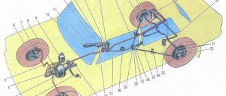
Description of the semi-trailer pneumatic brake system
The pneumatic actuator is the parts that sit between the brake and the control system that regulates the operation.
Pneumatic brake system for semi-trailer
Consists of the following parts:
- energy cells that supply power to the brake;
- Control block;
- brake.
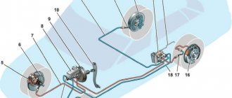
To ensure that the trailer's brakes are coordinated with the tractor's brakes, a semi-trailer air system is installed. It ensures the distribution of compressed air between the elements for braking, releasing and emergency braking. This is also indicated in the brake diagram of the Schmitz semi-trailer.
A huge variety of air distributors have the same structure: several pistons and valves.
Components
Operation occurs according to the principle: the energy drive components (pneumatic cylinders, energy accumulators, chambers) are fed with air pressure as follows:
- The compressor pumps the required amount of air.
- The four-circuit valve distributes the filling order (first - the circuit of the working system, then - the parking system).
- Braking when the ABS modulator is activated.
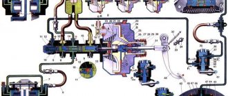
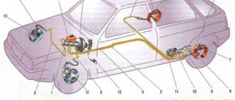
The diagram of the pneumatic system of a semi-trailer from domestic and foreign manufacturers of cargo vehicles describes in detail and shows all the components that, if desired, can be understood.
Outlines
To ensure safety, the pneumatic drive is divided into several circuits:
- Supply. It prepares air for the system.
- Compressor. This is a pump that pumps air into the supply circuit and regulates the pressure initially.
- Pressure regulator. It is sometimes installed on the compressor. The regulator maintains air density within acceptable limits so that the hoses and receiver do not burst due to high pressure. According to GOST, the norm is 6.5 - 8 atmospheres. When the pressure reaches 8 atmospheres, the unloading device is activated and releases air into the cylinders.
- Dehumidifier. Prepares the air by removing water and impurities. Modern dryers usually act as a filter and a regulator at the same time, so there is no separate pressure regulator circuit.
- Circuit breakers. Mix air with a special agent that protects the liquid from freezing.
- Receiver for storing air reserves.
- The safety valve is four-circuit, double or single. If one valve is damaged, the piston shuts off the air supply and the other circuit operates.
Note! A frequent cause of failures is damage to the pads and drums, which are subject to the greatest load.
ABS components
The braking system of a semi-trailer without ABS is not very popular. To provide maximum braking force, an anti-lock braking system is used.
Its components are installed between the tractor and the semi-trailer.
ABS components include:
- meter;
- Control block;
- electric and magnetic abs valves;
- connecting plug;
- burning lamps indicating the presence of errors in the system.
Operating principle.
Connecting the wires is carried out in the following steps:
- Control wire “A” is yellow. The control signal passes through it to the brake valve of the semi-trailer.
- Wire “B” is red. The energy of the compressed air is transferred to the brake mechanism.
Disconnection is carried out in reverse order.
Important! It is advisable to connect and disconnect ABS cables at a service center, where, if necessary, specialists can diagnose, replace or repair the modulator, tap, valves.
Malfunctions of this system and their causes
After the principle of operation of the pneumatic braking system, as well as its main components, has been considered, it’s time to talk about possible malfunctions, and unfortunately there can be quite a few of them. It is also worth saying that most breakdowns will not differ from malfunctions of other types of systems, so we will bypass some of them.
- There is no brake response when the brake pedal is pressed. This unpleasant phenomenon occurs if the braking system is not supplied with air from the cylinders or if there is no air there at all. In this case, it is urgent to diagnose the compressor and fix the problem as soon as possible.
- Braking distance is too long. Here everything is somewhat simpler, you just need to ask for help at a service station, where you should have the brake pedal adjusted, since the reason is most likely that it is loose.
- The brakes act out of sync. In this case, the problem lies in the gap variation on the brake linings. The treatment is also quite simple: come to the service station and check that the brake system in this place has been carefully adjusted.
Naturally, this is the smallest list of all possible faults, but they are the most common. In any case, if you notice that something is wrong with your brake system, you should immediately seek help.
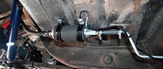
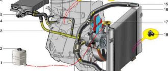
Compressor
This pneumatic drive element supplies compressed air to the system. It is processed in a purifier and then transported to tanks. The release of the air mixture from the cylinders is prevented by a check valve. The pressure indicator is determined by a pressure gauge. After activating the brake pedal, air enters the brake compartments through the opened valve, as a result of which the compression of the pads is triggered. The reverse process occurs using tension springs.
The compressor design includes a cylinder block, its head, crankcase, and locking covers. The crankshaft of the mechanism rotates in ball-type bearings and interacts with the pistons using pins and connecting rods. The front part of the crankshaft is equipped with a V-belt, oil seal and key. A fan is provided as a cooler. In the cylinder head above each working element there is a plug with a spring and a discharge valve. The lower connecting rod heads are equipped with shims.
pros
The use of the device in question is due to a number of advantages, namely:
- The pneumatic drive makes it possible to create significant clamping force on the pads with little impact on the control pedals.
- Availability, safety and ease of operation in normal air.
- The ability to accumulate a significant amount of potential air energy in special tanks, which allows for long-term and effective braking even if the compressor fails.
- Minor leaks of the air mixture are allowed, which are partially compensated by the supply of compressed air.
- Simplicity and convenience of connecting and conducting parts.
- High efficiency.
- Possibility of using the design for the operation of various additional automotive equipment.
Flaws
Now let's look at the disadvantages of the device:
- Relatively slow response due to the characteristics of the compressed air.
- Repair of a pneumatic drive requires complete or partial replacement of elements.
- Complexity of design and high cost of multi-circuit modification.
- Larger weight and size compared to its hydraulic counterpart.
- Significant power consumption for the compressor drive.
- Possibility of unit failure when condensate freezes in winter.
The brake pneumatic drive provides high force and contains a lot of elements. For example, at KamAZ this part includes about 25 instruments, 6 receivers, and about 70 meters of pipelines.
Lubrication and cooling
The pneumatic brake drive has a combined lubrication system. Oil is supplied from the main line through a pipe to the inside of the crankshaft. The connecting rod bearings are placed in an antifriction solution and are forcibly lubricated. The remaining elements receive oil by spraying. The waste from the crankcase is sent to the engine tank through a special outlet.
The cooling system of the pneumatic drive compressor is liquid type. It is connected to a similar unit of the power unit. When one of the pistons moves to the bottom position, a vacuum is created and air enters it through the cleaner and the intake valve. After the piston rises, the air mixture is compressed, then it flows through the valve into the cylinders and the main system. Then the whole process is repeated.
The air pressure indicator is limited by a special regulator, which reduces the cost of motor power to drive the compressor, which increases the operating life of the unit. The design with the regulator is located under the valves and contains a pair of plungers and seals with pushers. The plunger rocker arm is connected by a spring, the cavity under the intake valves is connected to the purifier pipeline, and the plunger channel is connected to the pressure controller.