2. Brown or orange wire with a black stripe, the second in the connecting block (located below the yellow one) - positive for the fog lamp.
3. Blue wire with a black stripe, the third in the connecting block - positive for the turn signal lamp.
4. Green wire, fourth in the block - plus to the rear light bulb.
5. Black wire, fifth in the block (penultimate) - negative for all flashlight lamps.
Serviceable headlights on the VAZ 2114 do an excellent job of illuminating the road surface at any time of the day. If a malfunction occurs, the beam strength deteriorates, the daw disappears and harmful flare appears. For safe driving, you need to monitor the optics, make adjustments and change modules in case of damage.
Design of the headlamp on the VAZ-2114
General view of the headlight
Almost all motorists use car headlights, but not everyone knows about the features of its design, as well as its structure. Thus, it is worth considering this issue in more detail.
Diagram of elements of the headlight unit of the VAZ-2114 car:
Diagram of the device and connection of the headlamp
- Reflector:
- Reflector bottom support.
- Wiper brush limiter;
- Lower reflector holder:
- Headlight diffuser.
- lamp flange:
- High beam thread;
- Low beam filament screen;
- Low beam thread;
- Turn signal lens;
- Lamp AI2-21-3;
- Stub. installed instead of the hydraulic corrector working cylinder;
- Upper reflector holder;
- Tension spring:
- Lever arm:
- Lever return spring;
- Screw for vertical headlight adjustment:
- Case:
- Sleeve;
- Working cylinder rod:
- Cuff;
- Working cylinder body:
- Headlight housing;
- Lamp AKG12-60+55;
- Screen;
- Lamp A12-4:
- Screw for horizontal headlight adjustment:
- Headlight mounting stud;
- Headlight housing;
- Hydraulic corrector main cylinder housing;
- Tubes connecting the master cylinder to the workers:
- Double piston:
- Drive screw;
- Lever;
- Nozzle:
- Lid:
- Block headlight;
- Mounting block;
- Relay for low beam headlights;
- Ignition switch;
- External lighting switch;
- Headlight high beam warning lamp;
- Headlight switch;
- Headlight high beam relay;
- I. Scheme of operation of the headlight hydraulic corrector:
- A-car with one driver:
- B-with the driver and cargo in the trunk;
- I. Headlight switching diagram;
- III. View of the headlight plug connector: a low beam plug; V. high beam connector: c side light connector: d ground connector
Practical recommendation for replacement
The headlight unit on a VAZ-2114 is quite simple and easy to change, but the process itself requires some practical and theoretical skills. Therefore, consider the sequential replacement process:
- Disconnect the negative terminal of the battery.
- We dismantle the radiator protective lining.
Removing the plastic protection of the top panel of the radiator
Unscrew the holding screw. It is better to remove the headlight assembly with turn signal
Unscrew the side mount of the headlight unit
We dismantle the headlight
Replacement is easy
Having figured out where the block that controls the operation of the PTF power circuit is located, replacing it is a trifle. It is much more difficult to correctly diagnose a breakdown. Therefore, if for some reason there is no power to the rear fog lights, you should start by checking the fuse and cleaning the contacts.
For the latter, you can use regular fine-grit sandpaper. This must be done extremely carefully, because the relay block contains electromagnets, with the help of which the contacts are switched (when the light button is pressed).
If there is no power supply to the VAZ rear lights, and the fog lights do not work together with it, then this does not indicate a breakdown of the relay, but a damage to the electrical circuit or a short circuit in the system (most often, the absence of a negative contact from ground).
To accurately determine the cause, it is advisable to use a multimeter. If only the rear lights do not light up, this indicates:
- damaged fuse;
- absence of 1, 2, 6 contacts (voltage on them);
- switch closure (momentary button);
- problem with electrical wiring (break).
As practice shows, the relay on the PTF VAZ 2114 fails extremely rarely. Most often, only a break in the contacting area or mass contact occurs due to body vibrations. A faulty relay should be the last thing to blame.
conclusions
Installing and replacing a VAZ-2114 headlight is a fairly simple and understandable process that every motorist can do with his own hands. So, if a car enthusiast is not able to carry out the process himself, he must contact a car service center, where they will always help.
I love articles like this, especially those that give a detailed analysis that you can do yourself on the weekend))
I'll have something to do this weekend)) I think I'll replace the headlights with new ones in a couple of hours. Quite a lot of nuances, especially for a beginner. Thanks for the instructions.
Schematic electrical diagrams, connecting devices and pinouts of connectors
Detailed color diagrams of the VAZ 2114 wiring (carburetor, injector) are provided with a description of the electrical equipment for various modifications. The information is intended for self-repair of cars. Many electrical circuits are divided into several sections for ease of viewing via a computer or smartphone; there are also circuits in the form of one picture with a description of the elements - for printing on a printer.
The VAZ 2114 (Samara-2) car is built on the VAZ 21093 platform and is an improved version of it. The first prototype of the hatchback was assembled back in 2000. A year later, the Volzhsky Automobile Plant produced the first pilot batch of 50 VAZ-2114 cars, and in the same 2001 the hatchback was first introduced to the market. The interior features a new instrument panel, a new steering wheel, an adjustable steering column, power windows and a new heater. Years of production 2114: 2001—2013
The fourteenth model was previously equipped with a 1.5 liter eight-valve engine, borrowed from the VAZ 2111 model with an injector. A little later it was replaced by the VAZ 11183-1000 version, which complies with the Euro-3 standard. The VAZ 2114 injector received a more powerful engine, and this is one of the reasons that the wiring of the 2114 has also changed.
A wiring harness has been added for connecting to the electronic switch. A harness has also appeared for connecting to the ignition module terminal.
Replacing high-voltage wires will require additional attention, because the connection procedure depends on the year of manufacture of the car. Until 2004, 4-pin ignition modules were installed, and after that - 3-pin. Connecting the adsorber valve to the injection system controller also provided another additional element. An adsorber is an electromechanical device used for ventilation and removal of condensate in a gas tank. Complications also affected the interior part. The dashboard received improvements in the form of the appearance of a BC (on-board computer), a new instrument panel and a change in the position of the glove compartment.
Malfunctions and repairs
To repair a VAZ headlight, it must be removed.
In the case of rear lights, you should replace standard sockets and chips with high-quality ones, and seal the joints with sealant. This will eliminate problems with contacts and improper operation of modules.
If the front lights of the VAZ do not work, then you need to inspect:
- chips and wiring;
- lamps;
- glass condition.
If problems are detected in the wiring, the faulty parts are replaced. Burnt-out light elements are removed and new ones are installed. If glass is broken, it is not difficult to re-glue it with sealant or remove the defect using special glue.
If after all the work the headlights do not shine well, then the optics need to be replaced with new ones. To do this, you need to decide on the manufacturer and purchase a set of suitable lamps.
Car modifications 2114
VAZ-21140 . Modification with an 8-valve injection engine VAZ-2111, 1.5 liters and 77 horsepower. Serial production from 2003 to 2007
VAZ-21144 . Modification with an 8-valve VAZ-21114 engine, 1.6 liters and 81.6 horsepower. Years of serial production: 2007-2013.
VAZ-211440 . Another modification released in 2007, it was equipped with a VAZ-11183 engine with a volume of 1.6 liters and a power of 82 horsepower. The car was discontinued in 2013.
What are fog lamps for?
The first prototype of the hatchback was assembled back in the year. And in combination with high-quality manufacturing materials, it ensured reliable operation. Many PTF kits contain special decorative plugs that add attractiveness and neatness to the installed headlights and facilitate the installation process. To summarize, we can say that in the first case, the qualifications of the work are minimal, and it can be done by yourself, without having specific knowledge, while working with an electrician requires a specialist who needs to be paid. When purchasing a bumper with holes for fog lights, you will need to purchase the lights themselves and all the necessary components for connection. Self-installation of PTF is the most common installation method, since it requires minimal financial investment. Otherwise, the clip fastening can be broken, and during subsequent installation the casing will not sit tightly in place.
There is a gear on the motor shaft that meshes with the teeth of the rack.
It should fit between the door clip and the door frame. Driver's door switch button. Installation of the VAZ 2114 engine start button. Do-it-yourself installation.
Wiring diagram VAZ-2114 for old models
Electrical diagram of car 2114: 1 - headlight; 2 [Installed on a part of the car] - fog lamp; 3 — ambient air temperature sensor; 4 — electric engine radiator fan; 5 — block for connection to the wiring harness of the engine control system; 6 — engine compartment lamp switch; 7 [Installed on a part of the car] - reserve block for connecting an audio signal with one terminal (the negative terminal is connected to the body); 8 — sound signal; 9 — liquid level sensor in the windshield washer reservoir; 10 [Installed on a part of the car] - brake pad wear sensor; 11 — low oil level sensor; 12 - generator; 13 [Installed on a part of the car] - engine compartment lamp; 14 — temperature indicator sensor; 15 — starter; 16 — battery; 17 [Installed on a part of the car] - relay for turning on fog lights; 18 — coolant level sensor in the expansion tank; 19 — sensor of insufficient brake fluid level; 20 — reversing light switch; 21 — windshield wiper gear motor; 22 — emergency oil pressure sensor; 23 — rear window washer electric pump; 24 — electric pump for windshield washer; 25 — instrument panel; 26 — mounting block of fuses and relays; 27 — brake signal switch; 28 — ignition relay; 29 - ignition switch (lock); 30 — glove box lighting lamp; 31 — switch for the glove compartment lighting lamp; 32 — rear window heating switch; 33 — rear fog light switch; 34 [Installed on a part of the car] - fog light switch; 35 - combined switch for side lights and headlights; 36 — alarm switch; 37 — steering column switches; 38 — brightness control for instrument lighting; 39 — illumination lamp for the headlight hydraulic adjustment control handle; 40 — socket for connecting a portable lamp; 41 — side direction indicator; 42 — interior lighting switch (front door open sensor); 43 — interior lamp; 44 — electric fan of the ventilation and heating system; 45 — additional resistor of the electric fan of the ventilation and heating system; 46 — switch for operating modes of the electric fan of the ventilation and heating system; 47 — illumination lamp for the handle of the operating mode switch of the electric fan of the ventilation and heating system; 48 — backlight lamp for the heater control unit; 49 — display unit of the on-board control system; 50 [Installed on part of the car] - trip computer; 51 — interior lighting switch (rear door open sensor); 52 [Installed on a part of the car] - block for connecting a clock; 53 — fuel module; 54 — ashtray illumination lamp; 55 — cigarette lighter; 56 — interior lamp; 57 — switch for the parking brake warning lamp; 58 — rear light; 59 — license plate light; 60 — additional brake light; 61 — heating element for heating the rear window; 62 — rear window wiper gear motor; A - numbers of pins in connecting blocks.
Relay location
So, the rear fog lamp relay is located on the driver’s side, under the steering wheel (just to the right of the fuse box, sometimes they are all covered with a plug or cover). There are only 3 pieces there. Sometimes they are covered with plugs. It should be noted that it is connected to a non-latching power button. This means that if you press it, it returns to its original state. But this is normal, since in it the contacts are paired through an electromagnet.
The PTF relay in old variations of VAZ cars was located under the hood, towards the fuse block. Now, more and more often, it is placed in the interior, under the steering wheel, in the area of the electronic unit. There is also a relay responsible for supplying power to the dashboard and a signaling device (if provided for by the design).
The rear fog light relay simultaneously combines 3 electrical circuits plus one spare line for 12 volts of static voltage. By the way, because of this, if it partially fails (meaning broken contacts due to vibration), you can fix the problem in a matter of minutes - simply transfer contacts from 1-2 to 6. The only caveat is that this procedure must be performed with the engine turned off and a disconnected battery terminal - some contacts are always energized, but without load. It can also cause a short circuit!
It is important to understand that initially the fog lamp relay does not connect this circuit, since the manufacturer by default installs conventional headlights without additional lighting. The circuit is closed after the fog lights are installed.
VAZ-2114 diagram (second option)
Electrical diagram of VAZ-2114 cars (without engine control system):
1 — block headlights; 2 — fog lights; 3 — air temperature sensor; 4 — electric motor of the engine cooling system fan; 5 — blocks connected to the wiring harness of the ignition system; 6 — engine compartment lamp switch; 7 — block for connecting to a single-wire type audio signal; 8 — sound signal; 9 — washer fluid level sensor; 10 — front brake pad wear sensor; 11 — oil level sensor; 12 - generator; 13 — engine compartment lamp; 14 — coolant temperature indicator sensor; 15 — starter; 16 - battery; 17 — relay for turning on fog lights; 18 — coolant level sensor; 19 — brake fluid level sensor; 20 — reverse light switch; 21 — windshield wiper gearmotor; 22 — oil pressure warning lamp sensor; 23 — block for connecting to the rear window washer electric motor; 24 — electric motor for windshield washer; 25 — instrument cluster; 26 — mounting block 2114; 27 — brake light switch; 28 — ignition relay; 29 — ignition switch; 30 — glove box lighting lamp; 31 — glove box lighting switch; 32 — rear window heating element switch; 33 — rear fog light switch; 34 — fog lamp switch; 35 — switch for external lighting lamps; 36 — alarm switch; 37 — steering column switches; 38 — switch for instrument lighting lamps; 39 — lamp for illuminating the headlight hydrocorrector scale; 40 — plug socket for a portable lamp; 41 — side direction indicators; 42 — lamp switch on the front door pillars; 43 — lamp for individual interior lighting; 44 — heater fan electric motor; 45 — additional resistor of the heater electric motor; 46 — heater fan switch; 47 — heater switch illumination lamp; 48 — lamp for illuminating the heater levers; 49 — on-board control system unit; 50 — trip computer; 51 — lamp switch on the rear door pillars; 52 — block for connecting the wiring harness of the engine control system; 53 — electric fuel pump and gasoline quantity sensor; 54 — front ashtray illumination lamp; 55 — cigarette lighter 2114; 56 — trunk lighting lamp; 57 — trunk light switch; 58 — interior lamp; 59 — parking brake warning lamp switch; 60 — rear external lights; 61 — rear internal lights; 62 — block for connection to the rear window heating element; 63 — license plate lights; 64 - additional brake signal located in the spoiler.
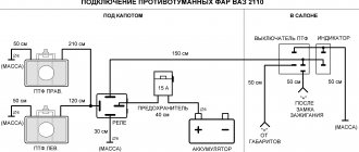
PTF connection diagram
Voltage is supplied to the electrical circuit by contact B+ from the generator. The mass is taken from the car body, not far from the location where the PTFs are installed. They begin to work when the switch key is pressed, provided that the low or high beam is working. To reduce the load on the contacts, a relay is connected to the circuit, which is installed from the factory in the engine compartment on the left mudguard; in addition, three fuses F8, F9, F10 are installed in the mounting block, which protect the fog light circuit.
Wiring diagram VAZ-2114 new models
The updated engine has a new injection scheme, so it was necessary to use some new devices, as well as replace the ignition coil with a more efficient one and adapted to Euro 3 conditions. In order to comply with them, the engine had to minimize the amount of CO at start-up. And for this it was necessary to lean the mixture. Since a lean mixture ignites worse, it needed a more powerful spark to spark. This explains the use of a coil of increased power.
- block headlights;
- gearmotors for headlight cleaners*;
- fog lights*;
- ambient temperature sensor;
- sound signals;
- engine compartment light switch;
- engine cooling fan electric motor;
- generator VAZ-2114;
- low oil level indicator sensor;
- washer fluid level sensor;
- front brake pad wear sensor;
- wire ends connected to the common windshield washer pump**;
- windshield washer pump;
- headlight washer pump*;
- wire ends for connecting to the rear window washer pump on VAZ-2113 and VAZ-2114 cars;
- low oil pressure indicator sensor;
- engine compartment lamp;
- wire lug for connecting to the engine management system wiring harness;
- windshield wiper gear motor;
- starter VAZ-2114;
- block connected to the wiring harness of the ignition system on carburetor cars;
- coolant temperature indicator sensor;
- reverse light switch;
- low brake fluid level indicator sensor;
- accumulator battery;
- low coolant level indicator sensor;
- relay for turning on fog lights;
- mounting block;
- brake light switch;
- plug socket for a portable lamp;
- hydrocorrector scale illumination lamp;
- parking brake indicator lamp switch;
- block for connecting a backlight lamp;
- switch for instrument lighting lamps;
- Understeering's shifter;
- hazard switch;
- front seat heating element relay;
- ignition switch;
- rear fog lamp circuit fuse;
- front seat heating elements circuit fuse;
- door lock circuit fuse;
- front ashtray illumination lamp;
- ignition relay;
- cigarette lighter VAZ-2114;
- glove box lighting lamp;
- glove compartment light switch;
- heater fan motor;
- additional heater motor resistor;
- heater fan switch;
- heater switch illumination lamp;
- heater lever illumination lamp;
- gear motors for electric windows of the front doors;
- right front door ESP switch (located in the right door);
- gear motors for locking front door locks;
- wires for connecting to the right front speaker;
- gear motors for locking rear doors;
- wires for connecting to the right rear speaker;
- door lock control unit;
- wires for connecting to radio equipment;
- headlight wiper switch*;
- rear window heating element switch;
- rear fog light relay;
- block for connection to the heating element of the right front seat;
- rear fog light switch;
- right front seat heating element switch;
- fog light switch*;
- switch for external lighting lamps;
- left front seat heating element switch;
- block for connection to the heating element of the left front seat;
- wires for connecting to the left front speaker;
- left front door power window switch (located in the left door);
- right front door power window switch (located in the left door);
- wires for connecting to the left rear speaker;
- side direction indicators;
- dome light switches on the front door pillars;
- dome light switches on the rear door pillars;
- lampshade VAZ 2114;
- individual interior lighting lamp;
- block for connecting to the wiring harness of the electric fuel pump;
- trunk light switch;
- instrument cluster;
- trunk light;
- on-board control system display unit;
- trip computer*;
- block for connecting the wiring harness of the engine management system;
- rear exterior lights;
- rear interior lights;
- pads for connecting to the rear window heating element;
- license plate lights;
- additional brake signal located on the spoiler.
Installation diagram of fog lights
The connection of fog lights is carried out according to certain rules. They, first of all, relate to the placement of PTF on the car. The locations for installing headlights are strictly defined.
Layout of daytime running lights
Manufacturers of modern car models pre-mark the PTF installation locations on the bumpers. As a rule, such lighting elements are most often available in the luxury version of the car. If the headlights themselves are missing, then their installation sites are closed with special plugs.
Distance at which fog lights can be placed
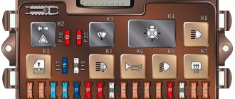
Relays and fuses VAZ 2114
F1 for 10 Amps (A) rear fog lights and rear fog light warning lamp. F2 for 10 A turn signal lamps, turn signal relay, hazard lights, hazard warning lights. F3 7.5 A lamps for interior lighting (both) and trunk, ignition lighting, powertrain control system control lamp, brake lamps, computer, if available. F4 20 A carrier, relay and rear window heating element. F5 20 A horn and its relay, cooling fan. F6 30 A power windows and their relays F7 30 A motor heater, headlight cleaner, windshield washer, cigarette lighter, glove compartment light bulb, rear window heating relay winding. F8 7.5 A right fog lamp. F9 7.5 A left fog lamp. F10 at 7.5 A left side marker, lamp signaling the inclusion of the side light, lamps for illuminating the sign, engine compartment, illumination of switches and instruments, instrument lighting switch. F11 at 7.5 A right side. F12 at 7.5 A right low beam. F13 at 7.5 A left low beam. F14 for 7.5 A left high beam and a light indicating that the high beam headlights are on. F15 at 7.5 A right far. F16 30 A - a light indicating insufficient oil pressure, brake fluid level, engagement of the parking brake, low battery, instrument cluster, relay for monitoring the health of lamps, indication of control systems, reversing lamps, turn indicators and their relays, as well as an alarm if turning mode is turned on, computer, generator excitation winding is turned on at the moment the engine starts.
Reversing lights
Lamps, which are a light-signal element that notifies you when you are reversing, can significantly increase the level of safety on the road.
The turning on of the rear lights indicates that the car is moving backwards, so you should be careful. Non-working lights can easily lead to accidents and collisions, for which you will ultimately be the culprit.
What is this?
3X headlights are white lighting fixtures. They turn on when shifting into reverse gear.
The main function is to ensure safety while driving. They signal other drivers about your maneuvers and illuminate the road when parking in the dark.