After its first appearance in 2003, the Mazda 3 was revised twice, taking into account current technologies. Second and third generation examples complement the original designs. With each update, the car's fuse diagram changed. The purpose of this component is to protect components, devices and the electrical network from overloads that can damage the vehicle.
A separate Mazda 3 fuse includes a plastic or ceramic housing that hides the contact group and the working element, which is destroyed by excessive current. Using a contact group, the device is connected to the network. Fuses eliminate the possibility of costly repairs in the event of a short circuit or vehicle fire. Fuse groups are marked in different colors to make it easier for the vehicle owner to replace failed elements. Before starting work, you need to study the decoding of each of the car's fuse boxes.
Mazda 3 fuses
Fuse blocks are installed in two places: in the space under the hood and in the interior of the car. Elements are marked depending on the maximum current flow. The first generation Mazda 3 cars have the following classification from lowest to highest:
| Fuse color | Maximum current, A |
| Grey | 2 |
| Light brown | 5 |
| Brown | 7,5 |
| Red | 10 |
| Light blue | 15 |
| Yellow | 20 |
| Light green | 30 |
| Orange | 40 |
The interior fuse box of the Mazda 3 of the first generation contains 6 cables that allow you to connect wire harnesses (3 on each side).
The fuses, which are located under the hood, are responsible for the stable operation of the engine cooling fan, starter, ignition and other technically complex elements of the car. The interior unit contains devices that provide operation of the cigarette lighter, audio system, security alarm, seat heater and other comfort elements. For the convenience of car owners, a diagram of the location of fuses on the cover of each block is provided.
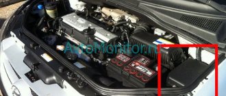
Engine compartment mounting block
Where are the fuses on the Lifan Solano?
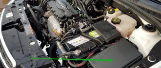
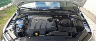
Another block on the Mazda 3-6 is installed in the engine compartment on the right side, when looking towards the hood. Below it is the wheel arch on the driver's side.
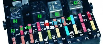
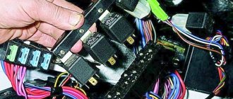
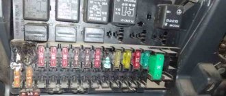
The fuse block flap on Mazda 3-6 is fixed with a special holder. To open it, lift the latch up. In this way, you can get to the fuses that are responsible for more complex electronic processes in the car, for example, the operation of the starter, horn, engine cooling system, ignition, etc. Each fuse has a specific color, indicating its power, for example, a red element has a power of 10 A, light green - 30 A, gray - 2A, etc.
The fuse box diagram for the Mazda 626 ge and other car models of this brand is located on the back of the cover.
Deciphering the electrical circuit of the fuse box on the Mazda 6 2008, which is located in the passenger compartment
| Element designation | Decoding |
| FAN | Cooling fans |
| P/ST | Power steering pump |
| BTN | Emergency lights, windshield washers, dimensions |
| HEAD | Backlight |
| PTC | RTS electrical circuit |
| ABS | ABS brake system |
| ENGINE | Power circuit that regulates engine operation |
| IG KEY 1 and IG KEY 2 | Egnition lock |
| STARTER | Starter |
| HEATER | Climate control |
| DEFOG | Heated rear window |
| FOG | Fog lights |
| HORN | Klaxon |
| (H/CLEAN) | Electric headlight washer |
| F/PUMP | Fuel pump |
| A/C MAG | Compressor clutch on air conditioner |
| (ALT) | Generator operation |
| ENG+B (ENG BAR 4) (ENG BAR 3) EGIING ENG BAR 1 ENG BAR 2 | Engine |
| ROOM | Dashboard, central locking, interior and trunk lighting |
| (D/LOCK 2) | Central locking operation |
| HEAD HIGH L HEAD HIGH R | Long range lighting |
| CIGAR | Cigarette lighter |
| RADIO | Audio system operation |
| MIRROR | Electric mirror control |
| TAIL R | Dimensions |
| OBD | Diagnostic relay |
| (TR/LOCK) | Lock circuit |
| CPU PWR | Electrical equipment control |
| HAZARD | Turn signals and emergency lights |
| (SUN ROOF) | Luke |
| WASHER | Electric windshield washers |
| P/WIND R P/WIND L | Window lifters |
| (ALARM) | Car security |
| (M/DEF) | Heating |
| HEAD LOW R HEADLOWL | Low lighting |
| SAS | Airbag |
| METER | Dashboard, ignition key lock |
| IGNITION | ABS brake system |
| WIPER (IG SIG) | Glass cleaners and washers |
| ENGINE | Electrical engine control |
| (SAS 2) | Airbags |
| (SEAT WARM) | Electrically heated seats |
| D/LOCK 1 | Central bell operation |
| A/C | Compressor clutch on air conditioner |
| P/WINDL** P/WIND R** | Reversing lighting |
This is interesting: Design, purpose and 6 signs of a malfunction of the front wheel hub of a car
Decoding the electrical circuit of the fuse box on the Mazda 6 in the engine compartment
| Fuse designation | Decoding |
| (FOG) | Fog lights |
| HORN | Klaxon |
| DEFOG | Heated rear window |
| (ETV) | ETV circuit |
| (F/WARM) | Heating |
| (CIRCUIT) | Fuel pump |
| (H/CLEAN) | Electric headlight washer |
| HEATER | Climate control fan |
| (A/C) | Compressor clutch on air conditioner |
| STARTER | Starter |
| MAIN | Engine |
Where are the fuses located?
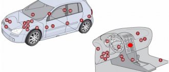
In first-generation Mazda 3 cars (2003-2009), one unit is located under the hood, the second in the cabin. A special feature of the second generation vehicle (2009-2013) is the presence of a fuse box and a relay box, which are located under the hood, and another one is located in the cabin. When developing the third generation cars (2013-2018), engineers returned to the scheme implemented in the original version of the Mazda 3.
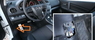
In cars manufactured before 2009, the fuse box in the passenger compartment can be found directly under the dashboard. While in the cabin, you should pay attention to the area on the left side of the steering column. In the next generation of cars, the fuses were located under the glove box, hidden by a massive plastic casing. In order to open the interior unit, you need to press the small transparent latch.
Owners of the latest version of the Mazda 3 need to go down to the area located to the side of the driver's feet. The plastic cover immediately comes into view, which hides the fuses.
The current generation car is equipped with a fuse box on the right side of the driver (rib area). It is securely hidden by a casing; the design includes brackets and plugs for fastening. Having opened the block, you can study all the presented fuse designations.
The second generation Mazda 3 hides fuses in approximately the same place as the latest car models. It is worth noting the smaller size of the casing. The plug is located on the back side, which makes access to the fuses somewhat difficult. In terms of the location of this block, there are no differences from the first generation machines. Before working on fuses or any other electrical components, it is important to turn off the ignition.
Basic electrical faults
Generator
It is produced in various modifications, installed relative to the model, and serves to convert mechanical energy into electrical current. The dw3w device (Mazda Demio generator) can be dismantled on your own without the help of qualified auto mechanics.
To remove a part from the hood when an urgent need arises, you will need to place the car under an inspection hole. By the way, it is possible to change the belt at the same time (replacing the Mazda Demio generator). Repairs must be carried out in stages.
- Pull off the cable (while under the car).
- Unscrew the tension bolt.
- Loosen the mounting bolt.
- Remove the belt from the pulley.
After removing the unit, replacing the alternator belt (Mazda Demio) also became possible. Thus, you can replace (replacing the Mazda Demio alternator belt) or the unit itself yourself.
Circuit breakers
In Mazda Demio, fuses perform similar functions - they protect the electrical network and devices. The fuse (Mazda Demio cigarette lighter), when the load is increased, burns out. A fuse (Mazda Demio fuse) can save the car from fire.
Radio tape recorder
The element of necessary comfort can be improved through aux (Mazda Demio 2002). Restyling can be done on your own. You will need a Mazda Demio transition frame and available tools.
In addition to the frames (transitional Mazda Demio), you need to remove the steering column casing, remove the insert from the small glove compartment, the air handles, the ashtray, and the radio. Next, to make an aux (aux Mazda Demio 2002), you need to work with the device board (you will need professional knowledge, a soldering iron).
Decoding Mazda 3 fuses
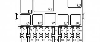
The car fuse diagram is important information, in case of damage to one or another fuse, you need to know the location of the fuses. The engine compartment block is represented by fuses Fc 1 to 36.
Fuse No. 1 is responsible for the electric fan and cooling. Number 2 – electric power steering pump. No. 3 – alarm signals and window washing, central locking and dimensions. No. 4 - headlights, No. 5 - RTS circuit, 7, 8, 19 - ABS, directional stability system, 9 - power circuit. Sensors 11 and 12 – ignition and starter relay. Number 13 - connects when ignition and disconnects when the starter is turned off (unlike 11). 15 - climate control, 17 - for heated rear windows. F20 - fog lights. Sound signals - No. 21. No. 23 – headlight washer fuse. Number 24 – fuel pump, 26 – air conditioning. Number 27 is a generator. Engine control - No. 30. No. 31 - interior lighting. Numbers 32 to 36 are responsible for engine control.
In the cabin there are sensors from 37 to 86:
- D/LOCK 2 – central locking;
- 39-40 — high beam;
- 43 – cigarette lighter;
- 44 – audio;
- 45 – mirrors;
- 46 – right dimensions;
- 47 – connectors for diagnostics;
- 49 – lock chain;
- 50 – control of electrical devices;
- 51 – turn signals and electric alarm;
- 52 — sunroof;
- 53 — glass washing;
- 55-56 – glass lifting;
- 57 – security system;
- 58 – heating;
- 60-61 – low beam;
- 65 – airbag;
- 67 – stability, steering;
- 68 – glass cleaning;
- 69 – engine control;
- 70 – glass cleaner;
- 74 – seat heating system;
- 75 – central lock;
- 76 – air conditioning compressor;
- 77-78 – glass lifting;
- 79 – light during reversing;
- 80 - roof hatch;
- 81 – left dimensions;
- 82 – fog lighting, dashboard lighting;
The missing numbers are backup safety elements. These also include fuses F83 - F86. In the interior mounting block there are relays No. 23 - low beam, 24 - automatic transmission selector, 25, 26 - speed of glass cleaning, 27, 28 - high beam and dimensions, respectively. Central locking relay: 31-32. The relay under the hood can be deciphered if you know the translation from English. For example: FOG - fog lights, H/CLEAN - headlight washing, HEATER - heating, etc.
The second version of protective elements in the cabin
| № | Denomination | A | Safety circuit |
| № 1 | R.SOCKET | A-15 | For other electrical equipment circuits. |
| № 2 | WIPER | A-20 | Protects windshield washers. |
| № 3 | A/C | A-15 | Responsible for climate control. |
| № 4 | RADIO | A-15 | Protects your audio system. |
| № 5 | R.WIPER | A-10 | Responsible for the operation of the rear wipers. |
| № 6 | ST/SG | A-7.5 | Responsible for the serviceability of the on-board computer. |
| № 7 | — | — | Free. |
| № 8 | ROOM | A-10 | Responsible for the light inside the cabin and in the trunk. |
| № 9 | MIRR DEF | A-7.5 | Protects the mirror heating. |
| № 10 | — | — | Free. |
| № 11 | DOOR LOCK | A-30 | Responsible for the operation of door locks. |
| № 12 | TAIL | A-15 | Free |
| № 13 | — | — | Free |
| № 14 | ENGINE | A-10 | Responsible for the operation of the on-board computer and ABS. |
| № 15 | METER | A-10 | Responsible for the reverse lights, turns and instrument panel. |
| № 16 | P/WIND | A-20 | Protects window regulators. |
| № 17 | P/WIND | A-30 | Protects window regulators. |
Procedure for replacing fuses
If necessary, the owner himself can replace failed fuse blocks (for example, headlight washers, climate control, etc.). It is enough to know the layout of the sensors and the functions that they mean (deciphering the diagram). Mazda fuses are replaced in the following order:
- The ignition must be turned off;
- Disconnect the battery from the power supply;
- Dismantle the outer protective cover of the fuse box;
- Deactivate the pads and harnesses that are connected to the fuse block;
- Use a screwdriver to unscrew the fastening screws;
- Using the latch, remove the device;
- Install a new fuse and repeat the procedure in reverse order.
DIY repair and maintenance
If an extraneous sound appears in the rear of the car, especially when the engine is running for a long time, you need to think about replacing the Mazda 3 fuel pump
To carry out this work, it is important to purchase new equipment and a filter system. The cost depends on the manufacturer
However, it is worth saying that there is not much difference - the service life is long in any case. Carrying out the work carefully will ensure not only the safe operation of the system itself, but also the entire vehicle as a whole. This allows us to say that the device can be considered a key component of the machine’s performance.
Description of the fuel pump
In order to gain access to the fuel pump, you must:
- Remove the carpet located in the car under the rear seats.
- After this, you need to remove the foam that is under it and find the small fuel pump chip and disconnect it.
- Next, go under the car and disconnect the gas tank itself.
- Disconnect the pipes leading to the fuel tank - remove the durable fittings that are in the public domain.
Important! Care should be taken when removing the special protection that separates the high-temperature exhaust system from this device. At first glance, it may seem that the Mazda 3 gas tank is large in size and weight, however, this is not the case - the device is made of plastic
As can be seen from all of the above, accessing the fuel pump is easy - even a novice car enthusiast can cope with such work. Working with the fuel pump relay is of particular importance. This requires certain knowledge and skills, but this, as a rule, is already important when performing repairs, where additional tools, knowledge and appropriate qualifications are required.
Fuel pump maintenance
In order to check the serviceability of the Mazda 3 fuel pump, you need to perform actions in accordance with a certain algorithm:
- Separate the mounting screws and remove the tie-down hooks in the luggage compartment.
- Remove the carpet under the rear seats by disconnecting the fasteners on the rear door carpet.
- Remove the gas tank cap and disconnect the electrical wiring, taking utmost care to keep the wires intact.
- Connect a voltmeter and crank the engine to take readings.
- When obtaining information about the battery voltage, it is necessary to check the conductivity. If it is missing, the fuel pump must be replaced.
- If there is no battery voltage, it is necessary to remove the trim panel under the fuse mounting block and disconnect the electrical relay of the fuel pump control unit.
- Disconnect the wire from the fuel pump starter terminal.
- With the engine turned on, measure the voltage and, if there is no voltage, check the functionality of the engine control fuse and electrical wiring.
- All changes must be made one by one between all connection wires and the Mazda 3 body.
Such measurements make it possible to determine the cause of a malfunction or places where they may appear in the near future and eliminate such failures in a timely manner and at minimal cost.
Fuel pump repair
Repairing a fuel pump is quite simple, however, it can take a lot of time. To do this, you simply need to disconnect the gas tank and perform a simple replacement of the fuel pump
In addition, it is important to understand that related problems may arise related to the vehicle's electrical wiring and therefore it is important to regularly measure the voltage
The functionality of the replaced fuel pump is checked by connecting the car battery terminals and running the engine for a short time. Even before the motor starts working, you can hear a sound that gives an idea of its performance.
Next, it is important to visually assess the presence of leaks from connections on the rear of the body
Important! All work must be carried out as far as possible from open flames and with the utmost care. Useful tips
Useful tips
In order to correctly perform all work related to replacing and servicing the gas tank and fuel pump, it is necessary to strictly follow certain operating algorithms. Only in this way can the functionality of the vehicle and its systems be ensured, which will certainly reduce the costs of subsequent repairs and maintenance. To perform work related to the Mazda 3 fuel pump, you must have a pit or overpass
Before starting work, it is important to drain the fuel, which will allow you to replace the pump as quickly and safely as possible.
Fuse and relay box Mazda 6 from 2002
Cars considered were 2002, 2003, 2004, 2005, 2006, 2007, 2008
Where is the Mazda 6 fuse and relay box located?
In the cabin, below to the left of the driver's foot.
Decoding
| Fuse | Nominal,A | Purpose | |
| 1 | ENGINE I.G. | 15 | Engine management system |
| 2 | METERIG | 15 | Instrument cluster |
| 3 | SEAT | 15 | Heated seats, heated rear window |
| 4 | M.DEF | 7,5 | Heated mirrors, fuse for various circuits* |
| 5 | WIPER | 20 | Windshield wipers and washers |
| 6 | SAS | 15 | Anti-lock brakes, active safety system (airbags) |
| 7 | BACK | 5 | Reversing light* |
| 8 | A/C | 15 | Air conditioner |
| 9 | METER ACC | 5 | Instrument cluster |
| 10 | CIGAR | 15 | Mazda 6 cigarette lighter fuse |
| 11 | ROOM | 15 | Interior lighting, trunk/luggage compartment lighting |
| 12 | R.WIPER | 10 | Rear window/rear door window wiper* |
| 13 | MIRROR | 5 | Mirror control |
| 14 | — | — | — |
| 15 | P/WIND | 20 | Electric windows |
| 16 | DOOR LOCK | 30 | central locking |
| 17 | P/WIND | 30 | Electric windows |
Relay in the interior of a Mazda 6 car
21 - heater fan relay, 22 - fuel pump relay
Relay and fuse box in the engine compartment
fuse decoding
| Fuse | Denomination, A | fuse circuit | |
| 1 | SPARE | 20 | — |
| 2 | SPARE | 15 | — |
| 3 | SPARE | 10 | — |
| 4 | — | — | — |
| 5 | GLOW SIG | 5 | — |
| 6 | INJ | 15 | Engine management system |
| 7 | ENG BAR | 10 | Air flow sensor, engine management system |
| 8 | ENG BAR2 | 15 | Oxygen sensor |
| 9 | HEAD LR | 15 | Low beam (right headlight) |
| 10 | HEAD LL | 15 | Low beam (left headlight) |
| 11 | HEAD HL | 10 | High beam (left headlight) |
| 12 | HEAD HR | 10 | High beam (right headlight) |
| 13 | — | — | — |
| 14 | HAZARD | 10 | Alarm |
| 15 | STOP | 15 | Brake lights |
| 16 | ENG+B | 10 | Electronic engine control unit and automatic transmission |
| 17 | — | — | — |
| 18 | FUEL PUMP | 20 | Fuel pump |
| 19 | IG KEY 1 | 40 | Fuse for various circuits |
| 20 | — | — | — |
| 21 | — | — | — |
| 22 | GLOW | 40 | — |
| 23 | IG KEY 2 | 30 | Fuse for various circuits |
| 24 | BLOWER | 40 | Heater fan motor |
| 25 | BTN | 40 | Interior lighting, central locking |
| 26 | HEATER | 20 | Heater |
| 27 | DEFOG | 40 | Rear window/rear door defroster |
| 28 | ABS | 60 | Anti-lock brake system, fuse for various circuits |
| 29 | AD FAN | 30 | Condenser fan motor, fuse for various circuits |
| 30 | FAN | 30 | Condenser fan motor, fuse for various circuits |
| 31 | TAIL | 10 | Side lights, instrument cluster illumination |
| 32 | ILLUMI | 10 | Interior lighting |
| 33 | MAG | 10 | Electromagnetic clutch |
| 34 | AUDIO | 15 | Radio tape recorder |
| 35 | P.SEAT | 30 | — |
| 36 | — | — | — |
| 37 | SEAT DEICER | 15 | Fuse for various circuits* |
| 38 | H/CLEAN | 20 | Headlight cleaner |
| 39 | FOG | 15 | Fog lights* |
| 40 | MAIN | 100 | Main fuse |
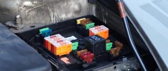
Relay under the hood
Purpose
1 - main fuse, 6 - cooling fan relay No. 2, 7 - horn relay, 8 - cooling fan relay No. 3, 9 - starter relay, 10 - cooling fan relay No. 4, 11 - bass speaker relay, 12 - rear window heater relay, 13 - fog lamp relay, 14 - air conditioning relay, 15 - main relay, 16 - headlight relay, 17 - headlight relay, 18 - cooling system fan relay No. 1, 19 - headlight washer relay, 20 - fog light relay
Removing and installing the mounting block under the hood and in the cabin
Replacing the main fuse
- Disconnect the cable from the negative terminal of the battery.
- Remove the cover of the mounting block in the engine compartment.
- Remove the main fuse in the sequence of numbers shown in the figure.
1 - nut, 2 - bolt, 3 - main fuse.
Install in the reverse order of removal.
Note on block removal
- Press the latches as shown in the picture.
- Lift the mounting block and remove the bolts.
Removing and installing the mounting block in the cabin
- Disconnect the cable from the negative terminal of the battery.
- Remove the front side interior trim on the left side.
- Remove the mounting block in the passenger compartment in the sequence of numbers shown in the figure.
1 — connectors, 2 — bolt, 3 — mounting block in the cabin.
Install in the reverse order of removal.