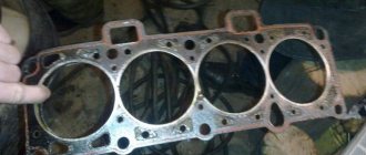
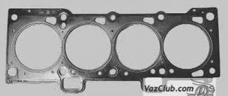
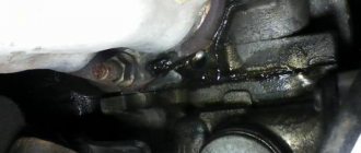
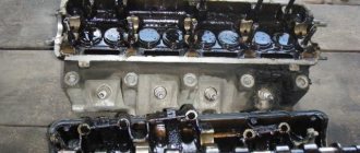
If a leak of engine oil or coolant is detected at the junction of the cylinder head with the cylinder block, remove the head and replace its gasket. A leak can also occur due to warping of the cylinder head due to overheating. The cylinder head gasket of the VAZ-11183 engine is made of metal asbestos sheet, and on the VAZ-21116 and VAZ-11186 engines it is metal. The procedure for replacing the gasket on all three engines is the same and is shown using the example of a VAZ-11183 engine (8 valves). Replacing the head gasket of a VAZ-21126 engine (16 valves) is described separately, see the article “Replacing the cylinder head gasket on a Lada Priora car”
To replace the head gasket of VAZ-11183, VAZ-21116 and VAZ-11186 engines, do the following. You will need: a torque wrench, keys “13”, “17”, “19”, socket heads “10”, “ 13", "17", hex wrench "10", screwdriver.
Warning
10. ...and phase sensor.
11. Remove the cylinder head cover
12. Remove the front cover of the gas distribution mechanism drive (see “Installing the piston of the first cylinder to the TDC position of the compression stroke”).
13. Loosen the camshaft pulley bolt while holding the camshaft from turning (this can be done by inserting a large screwdriver or spudger into the pulley hub holes).
14. Remove the timing belt (see “Replacing the timing belt and tension pulley”).
15. Completely remove the camshaft pulley mounting bolt...
16. ...and remove the pulley.
If the pulley is pressed onto the shaft, use a puller (see figure below)
19. Loosen the clamps and disconnect the five cooling system hoses from the thermostat pipes.
20. Unscrew the nut securing the tip of the “mass” wire...
28. ...finally unscrew the head mounting bolts and remove them together with washers.
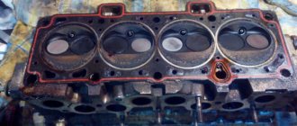
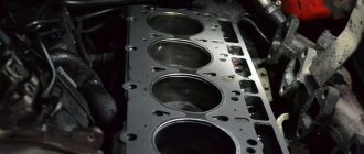
29. Remove the cylinder head.
WARNING
Do not jam a screwdriver or other tools between the cylinder head and the cylinder block.
USEFUL TIPS
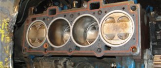
31. Clean the mating surfaces of the cylinder head and cylinder block (they should be dry and clean) and remove oil from the threaded holes in the block for the head mounting bolts.
WARNING
If you do not remove the oil from the threaded holes for the head bolts, then cracks may appear in the cylinder block when the bolts are tightened, since the oil is not compressed.
34. Install the head on the block, first making sure that the crankshaft and camshaft are in the TDC position (both valves of the 1st cylinder must be closed). Tighten the cylinder head bolts in the specified sequence in four stages:
- Back
- Forward
In what cases is it necessary to tighten the block?
During the operation of any car, including the VAZ 2170 Priora, the engine head is exposed to long-term cyclic effects of gases located in the engine cylinders. On older power units, the tightening of the cylinder head screws could weaken under such loads and periodically needed to be brought to a normal level. Today, all VAZ Priora engines use bolts made of special steel, which are tightened once for their entire service life.
If a coolant and oil leak occurs, there is no point in further tightening and tightening these bolts, since this will not improve the tightness of the joint. The only correct way to combat a leak is to remove the head, check the evenness of the mating surfaces and replace the gasket. After performing any repair work related to removing the head from the engine, it must be tightened in compliance with all necessary conditions.
The video from the author Alex ZW shows the process of installing the cylinder head on an 8-valve engine.
DIY torque wrench
| Size | Strength class Nm* | ||||||||
| 3.6 | 4.6 | 5.6 | 5.8 | 6.8 | 8.8 | 9.8 | 10.9 | 12.9 | |
| M1.6 | 0,05 | 0,07 | 0,09 | 0,11 | 0,14 | 0,18 | 0,21 | 0,26 | 0,31 |
| M2 | 0,11 | 0,14 | 0,18 | 0,24 | 0,28 | 0,38 | 0,42 | 0,53 | 0,63 |
| M2.5 | 0,22 | 0,29 | 0,36 | 0,48 | 0,58 | 0,78 | 0,87 | 1,09 | 1,31 |
| M3 | 0,38 | 0,51 | 0,63 | 0,84 | 1,01 | 1,35 | 1,52 | 1,90 | 2,27 |
| M4 | 0,71 | 0,95 | 1,19 | 1,59 | 1,91 | 2,54 | 2,86 | 3,57 | 4,29 |
| M5 | 1,71 | 2,28 | 2,85 | 3,80 | 4,56 | 6,09 | 6,85 | 8,56 | 10,3 |
| M6 | 2,94 | 3,92 | 4,91 | 6,54 | 7,85 | 10,5 | 11,8 | 14,7 | 17,7 |
| M8 | 7,11 | 9,48 | 11,9 | 15,8 | 19,0 | 25,3 | 28,4 | 35,5 | 42,7 |
| M10 | 14,3 | 19,1 | 23,8 | 31,8 | 38,1 | 50,8 | 57,2 | 71,5 | 85,8 |
| M12 | 24,4 | 32,6 | 40,7 | 54,3 | 65,1 | 86,9 | 97,7 | 122 | 147 |
| M14 | 39 | 52 | 65 | 86,6 | 104 | 139 | 156 | 195 | 234 |
| M16 | 59,9 | 79,9 | 99,8 | 133 | 160 | 213 | 240 | 299 | 359 |
| M18 | 82,5 | 110 | 138 | 183 | 220 | 293 | 330 | 413 | 495 |
| M20 | 117 | 156 | 195 | 260 | 312 | 416 | 468 | 585 | 702 |
| M22 | 158 | 211 | 264 | 352 | 422 | 563 | 634 | 792 | 950 |
| M24 | 202 | 270 | 337 | 449 | 539 | 719 | 809 | 1011 | 1213 |
| M27 | 298 | 398 | 497 | 663 | 795 | 1060 | 1193 | 1491 | 1789 |
| M30 | 405 | 540 | 675 | 900 | 1080 | 1440 | 1620 | 2025 | 2430 |
| M33 | 550 | 734 | 917 | 1223 | 1467 | 1956 | 2201 | 2751 | 3301 |
| M36 | 708 | 944 | 1180 | 1573 | 1888 | 2517 | 2832 | 3540 | 4248 |
| M39 | 919 | 1226 | 1532 | 2043 | 2452 | 3269 | 3678 | 4597 | 5517 |
| M42 | 1139 | 1518 | 1898 | 2530 | 3036 | 4049 | 4555 | 5693 | 6832 |
| M45 | 1425 | 1900 | 2375 | 3167 | 3800 | 5067 | 5701 | 7126 | 8551 |
| M48 | 1716 | 2288 | 2860 | 3313 | 4576 | 6101 | 6864 | 8580 | 10296 |
| M52 | 2210 | 2947 | 3684 | 4912 | 5895 | 7859 | 8842 | 11052 | 13263 |
| M56 | 2737 | 3650 | 4562 | 6083 | 7300 | 9733 | 10950 | 13687 | 16425 |
| M60 | 3404 | 4538 | 5673 | 7564 | 9076 | 12102 | 13614 | 17018 | 20422 |
| M64 | 4100 | 5466 | 6833 | 9110 | 10932 | 14576 | 16398 | 20498 | 24597 |
| M68 | 4963 | 6617 | 8271 | 11029 | 13234 | 17646 | 19851 | 24814 | 29777 |
*where Nm is torque. It is equal to the product of force and the arm of its application and is measured in newton meters. Thus, if we apply a force of 1 Newton (perpendicular to the end of the wrench) to a wrench 1 meter long (arm), we will obtain a torque of 1 Nm.
When repairing a car, almost every car enthusiast is faced with the problem of tightening a threaded connection with a certain force, but there is no torque wrench. And it costs a lot of money. So I ran into this problem: I don’t have the money to buy it, but I really need it.
- old ratchet wrench
- 10 mm hex key.
- two 8 mm nuts.
- scales with a digital dial up to 40 kg. (bought here)
- piece of strip 4*40 mm
- welding machine
- Angle grinder (grinder)
- pliers, hammer, file and other plumbing tools.
I disassemble the ratchet and remove the locking mechanism from it; I won’t need it.
I cut the hex key as shown in the photo
Now I weld the hexagon to the head of the ratchet so that the handle of the wrench and the hexagon in the assembled state are parallel.
Now I weld the mount to the key handle.
I weld two nuts to the hexagon. Two because the hexagon turned out to be short, so I decided to lengthen it. The hook of the scale will cling to the nut. My DMK is almost ready, we can start assembling.
And painting
All you have to do is wait until the paint dries and attach the scales. The paint has dried. I attached the scales and this is what happened.
I decided to secure the scales with cable ties. This fastener allows you to quickly remove and use the scale for its intended purpose.
That's not all, all that remains is to make the calculations. At what scale readings will there be a particular tightening torque? This is the main disadvantage of a homemade DMK.
From the school physics course we know: 1 N (Newton) = 0.1019716212978 kg. 1 kg. = 9.806649999999 N (Newtons).
The tightening torque can be calculated using the following formula: kgf•m = m / (1 / L) where: kgf•m – kilogram of force per meter (force applied in kilograms) m – scale readings L – arm length in meters (distance from the center of the bolt before attaching the scales)
To convert the applied force into Newtons you need: N•m = kgf•m * 9.81 where: N•m – Newton per meter kgf•m – kilogram per meter of force
Most often, the tightening torque is written in Newtons, but our DMK shows the force in kilograms. For example, I need to tighten the nut with a force of 20 N. In order to find out what readings should be on the scales, we will use the formula
: m = Н * 0.102 * (1 / L) where: m – scale readings Н – tightening torque with which the threaded connection needs to be tightened L – arm length in meters (distance from the center of the bolt to the scale mounting).
m = 20 * 0.102 * (1 / 0.114) = 17.89 kg.
It follows that in order to tighten the nut with a force of 20 N, the scale should read 17.89 kg.
Many motorists from time to time have to deal with a difficult task - loose wheel rims, which directly affects the safety of movement. Therefore, car enthusiasts should pay utmost attention to wheel bolt patterns. If the correct installation parameters relative to the axle are not observed, the wheel disk is not securely fixed enough, and the optimal tightening torque value is not achieved.
The main criteria that you should focus on when performing work are the number of bolts and the diameter of the circumference of the seats. Several ways to determine the last parameter are popular among drivers. However, not all methods can be called effective.
The simplest and most understandable method is the following:
- First you need to set the distance between the walls of the holes using a caliper.
- Then you need to add the diameter of the fixation hole to a certain value.
The resulting size will determine the distance between adjacent holes.
A large number of motorists adjust the bolt pattern to new wheels, the diameter of which is slightly larger than the original version. When installing such products, centering rings are used.
The main task of the car owner is to choose rims of optimal weight and strength. The last factor plays a decisive role, since the wheels constantly take on serious loads and impacts. Also, do not neglect balancing, which will avoid discs from beating while driving.
The bolt pattern is carried out in strict compliance with three main parameters:
- PCD – circle diameter;
- ET – disc offset;
- DIA is the diameter of the central hole.
Domestic cars
Hyundai
Diagnosis of malfunction of the gas distribution mechanism
The process of diagnostics and identification of the source of failure is quite complex. Sometimes, without digital equipment, it is impossible to conduct a full inspection and assess the general technical condition of components and assemblies.
- Always go by ear. Feel the motor running. If you hear extraneous, previously uncharacteristic sounds, knocking on “cold” or “hot” - most likely the reason is in the timing belt;
- Pay attention to the level of fuel consumption, acceleration dynamics, and the informativeness of the accelerator pedal. Passivity, poor “responsiveness” are factors indicating a possible breakdown;
Countersinking saddles
When repairing the cylinder head yourself, be prepared for the most monotonous and lengthy process - countersinking. A lot depends on its quality:
- tight fit of the valve to the seat;
- compression ratio in the combustion chamber.
The seat grinding work is carried out with a special tool - a roller cutter (less often - a countersink). With its help, a not quite finished seat can be given the desired shape so that the valve fits more tightly. Start work with a countersink at 60 degrees.
As soon as metal removal has begun in a circle, change the nozzle - take a countersink with a cone angle of 120 degrees. Work with it until a clear round edge appears. The final stage of countersinking is done with a 90-degree cone - it should go through the working chamfer of no more than 1.5 mm. Further grinding of the valve will increase it to the required value.
Replacing valves on a 16-valve Lada Granta engine
Necessary tools, materials:
- automobile set of tools, heads;
- pliers, flat head/phillips head screwdrivers;
- collet - springy split sleeve;
- magnet, medical tweezers;
- metal tube for removing valves;
- desiccant;
- timing kit: bearings, rollers, nut;
- rags;
- additional lighting.
Sequencing:
- We place the car on the inspection hole and cool the engine.
- Open the hood and drain the antifreeze from the cooling system using the drain valve in the lower perimeter of the radiator.
- We disconnect the battery terminal to avoid a short circuit in the network.
- Remove the decorative cover on the engine.
Removing the engine cover
- Loosen the clamp and remove the throttle valve pipe.
- Remove the mass air flow sensor.
- Use a hexagon to “5” to unscrew the screws securing the plastic timing belt protection.
Removing the timing cover
- Using a flat-tip screwdriver, move the tensioner to the side, remove the drive belt and tensioner rollers from the motor. Clean it and fill it with new oil.
- We fix the gears on the camshaft.
We also shoot videos at the same time.
- On the radiator side, unscrew the air receiver clamp.
- From the interior side, remove the exhaust manifold.
- We remove the ignition sensor block and oil pressure sensor.
- Along the perimeter, unscrew the eight screws securing the valve cover and remove it from its seat.
- Use a key to “14” to unscrew the camshaft fastenings.
- Use a magnet to remove the pushers and arrange them in strict sequence.
We extract the hydraulic pushers with a magnet
- Loosen the clamps and remove the rubber pipes from the thermostat.
- Unscrew the bolts securing the head and set it aside on a clean surface.
The valves are already visible, we’ll get to them soon
- Using a knife, we separate the gasket from the head body; it must be replaced.
Putting the valve back in
- We dry out the valves, remove the spring and metal washer.
- We remove the caps with a puller; they also need to be replaced.
- We remove the valves.
- We clean the area where the head sits and remove old grease: paste, carbon deposits, dirt.
- We install new valves, lubricate the surface of the head with a thin layer of engine oil.
- We insert new washers, springs, crackers. We set acceptable gaps.
- We assemble the structure in reverse order.
Clean block and new valves
Tuning
Initially, the manufacturer puts additional features into its engines to make any changes in the following options. However, the 11186 engine can be upgraded independently. The following types of tuning are considered standard:
- camshaft - replacing a standard part with a Nuzhdin 10.93 or Dynamics 108 camshaft;
- cylinder block - boring to 86 - 88 mm (pistons and connecting rods of the appropriate size will be required);
- intake manifold - zero resistance filter, damper with a diameter of 54 mm, grinding of the internal surfaces of the channels;
- catcollector - replacement with a spider according to the 4: 2: 1 scheme;
- Timing: installation of lightweight T-valves;
- The head is a milling head.
A setting that adds 30% power is considered safe (“resourceful”) for the engine. That is, for 87 liters together with there will be 29 liters, which accordingly gives about 115 liters together with. Further adjustment becomes dangerous, since the service life will decrease in arithmetic progression. This method is used by athletes, but not by ordinary motorists.
Therefore, the 11186 engine has a significant drawback - valve bending. The manufacturer partially corrects the situation through resource-intensive Gates timing belts. In other respects, the internal combustion engine was superior to the existing analogues at that time, with the exception of the 21114 engine taken as a basis.
Tools:
- 5 mm hex key
- Ratchet
- Extension
- Head 8 mm
- Head 10 mm
- Head 13 mm
- Torx head E14
- 15 mm socket wrench
- Straight wrench 17 mm
- 8 mm curved socket wrench
- Wrench
- Final Attack Collar
- Key Impact 17mm
- Medium flathead screwdriver
- Medium Phillips screwdriver
- Screw jack
- Balloon Key
- A special key for turning the tensioner pulley (or circlip remover)
- Camshaft pulley wrench (or handle extension)
- Knife (or scraper)
- Funnel
- Universal extractor (if necessary)
- Calibers
- Regulator valve
- Tweezers
- Micrometer
Spare parts and consumables:
- Shoes - 2 pcs.
- Technical capabilities
- Coolant
- Head gasket
- Cap bolts (if necessary)
- Engine oil
- Thickness (if necessary)
- Rags
Notes:
If there is engine oil or coolant leaking from the cylinder head to cylinder block joints, remove the cylinder head and replace the cylinder head gasket. Leaks can also occur due to deformation of the cylinder head due to overheating. The cylinder head gasket of the VAZ 11183 engine is made of metal-asbestos fabric, and on the VAZ 21116 and VAZ 11186 engines it is made of metal. The procedure for replacing cylinder head gaskets on all three engines of a Lada Grant car is the same and is shown using the example of a VAZ 11183 engine. Replacing the cylinder head gasket for a VAZ 21126 engine is described separately.
The cylinder head gasket is a one-time use, so it must be replaced every time the cylinder head is removed.
1. Set the piston of cylinder 1 to TDC position on the compression stroke, then leave the front timing cover removed.
2. Reduce the pressure in the fuel system of the car engine if work is carried out immediately after driving.
3. Disconnect the cable from the negative terminal of the battery.
6. Disconnect the air inlet hose and harness connector from the throttle body as described here.
7. Disconnect the high-voltage cable ends from the spark plugs.
8. Disconnect the harness from the oil pressure warning light sensor connector.
9. Disconnect the connector from the valve timing sensor.
10. Then disconnect the wiring harness from the coolant temperature sensor (coolant temperature sensor) of the engine management system. The sensor is located on the thermostat.
11. Remove the cylinder head cover as described here.
12. Remove the timing belt and tension pulley as described here.
13. Loosen the camshaft pulley mounting bolt, preventing the camshaft from turning (this can be done by inserting a camshaft locking wrench into the pulley hub holes, or inserting a 10mm extension with an extension into the camshaft pulley hole and inserting this onto the rear timing belt locking nut covers).
14. Finally, remove the camshaft pulley bolt and remove the camshaft pulley.
Note:
If the pulley is tightly seated on the camshaft shank, remove it with a universal puller. To do this, install a removable screw on the camshaft pulley bolt previously screwed into the shaft (so as not to damage the threads in the camshaft).
15. Using a 10 mm socket, unscrew the two bolts and the nut securing the rear timing cover.
16. Remove the rear timing cover.
17. Disconnect the wire from the coolant temperature gauge sensor (the sensor is screwed into the cylinder block under the thermostat).
18. Loosen the clamps and disconnect the five coolant hoses from the thermostat connections.
19. Unscrew the nut securing the ground wire terminal and remove the wire.
20. Disconnect the injector cable connectors as described here.
21. Disconnect the fuel line from the fuel line.
22. Disconnect the brake booster hose from the intake module fitting by loosening the clamp securing it.
23. Disconnect the upper ends of the spacers from the exhaust manifold as described here.
24. Disconnect the oxygen sensor cable connectors and remove the associated cable clamps from the holes in the steering gear heat shield as described here.
25. Disconnect the sub muffler downpipe from the catalyst flange and disconnect the catalyst support bracket from the cylinder block as described here.
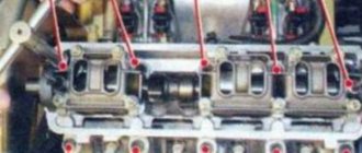
26. Using an E-14 socket, loosen the ten bolts in the order shown in the photo.
27. Finally, unscrew the cylinder head mounting bolts and pull them out along with the washers.
Note:
The cylinder head bolts will come out with repeated use. Replace bolts whose length (excluding head height) is more than 135.5 mm. Before installing the cylinder head on a Lada Granta VAZ 2190, lubricate the bolts with a thin layer of engine oil.
28. Remove the cylinder head from the engine.
Note:
Do not insert a screwdriver or other tools between the cylinder head and the cylinder block.
To remove the cylinder head from the gasket, insert a screwdriver under the catalytic converter and use it as a lever to lift it up. It is more convenient to remove the cylinder head from a Lada Grant car with an assistant, since it is quite heavy.
29. Remove the cylinder head gasket.
30. Clean the mating surfaces of the cylinder head and cylinder block (must be dry and clean) and wipe off oil from the threaded holes in the block for the cylinder head bolts with a rag.
Note:
If the oil is not removed from the cylinder head bolt threads, cracks may appear in the cylinder block when the bolts are tightened because the oil does not compress.
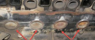
Check the presence of two control sleeves in the sockets of the outer holes of the cylinder block for the cylinder head mounting bolts. If, when removing the cylinder head from the vehicle, the bushings remain in the cylinder head or come out of the block seats, press them into the cylinder block until they stop.
31. Install a new cylinder head gasket on the cylinder block (the gasket must be dry and clean) along the installation sleeves. In this case, the hole for the passage of oil in the VAZ 11183 engine gasket (with a copper rim) should be in the range from the 3rd to the 4th cylinder.
32. Install the cylinder head onto the cylinder block, first making sure that the crankshaft and camshafts are in the TDC position (both valves of the 1st cylinder must be closed). Tighten the cylinder head bolts in a four-stage sequence: 1st - torque 20 Nm; 2nd - torque 69.4-85.7 Nm; 3 ° - turn the bolts 90 °; 4 ° - finally tighten the bolts to 90 °.
33. Install the removed parts onto the cylinder head and connect the hoses and cables in the reverse order of removal.
Note:
Install the camshaft pulley so that the protruding part of the hub faces the engine.
36. Check and, if necessary, adjust the clearances when the valve operates.
37. Adjust the timing belt tension as described here.
How to change valves on a Lada Granta with an 8-valve engine
Required tools:
- desiccant;
- cap puller;
- set of heads;
- knob;
- rags;
- new valves;
- additional lighting.
Sequencing:
- Remove the decorative cover from the motor.
- We disconnect the attachments, pipes, blocks with electrical wires.
- Using a “14” wrench, unscrew the bolts around the perimeter and remove the camshaft from the cylinder head.
We removed the cover and you can see the camshaft. We got to the cylinder block.
- We remove the pushers.
- Use a desiccant to remove the springs from the valves and the valve plate.
- When access to the valves is ensured, remove the old valves one by one. Clean the surface of the seat and apply a thin layer of engine oil. We install new ones, pre-drying them.
Valves close up
- Adjusting the gap.
Remove the timing cover, then remove the spark plugs for convenience. Check the valve clearance
- We complete the assembly.
How much do valves cost for a Lada Granta: a set of original ones from 650 rubles. Foreign analogues are 100 - 150 rubles more expensive.
Rear suspension Lada Kalina / Lada Kalina (VAZ 1118, 117, 1119)
Tightening torques for threaded connections
Name of units and parts
Tightening torque, Nm
Wheel bolts
Rear wheel bearing nut
Bolt nut for the lower shock absorber mounting to the rear suspension arm
Nut securing the rear suspension shock absorber rod to the body
Nuts of bolts securing the rear suspension arm to the bracket
Nuts securing the rear suspension arm bracket to the body
The rear suspension of the car is semi-independent, made on an “elastic” beam with trailing arms, coil springs and double-acting telescopic shock absorbers.
The rear suspension beam consists of two trailing arms connected by a U-shaped cross member. This cross-section provides the connector (cross member) with greater bending rigidity and less torsional rigidity. The connector allows the levers to move relative to each other within small limits. The levers are made of pipes of variable cross-section, which gives them the necessary rigidity. Brackets are welded to the rear end of each lever for attaching the shock absorber, rear brake assembly and wheel hub axle. At the front, the beam arms are bolted to removable brackets for the body side members. The mobility of the levers is ensured by rubber-metal hinges (silent blocks) pressed into the front ends of the levers.
The lower shock absorber eye is attached to the beam arm bracket. The shock absorber is attached to the body by a rod with a nut. The elasticity of the upper and lower connections of the shock absorber is provided by a rod cushion and a rubber-metal bushing pressed into the eye. The shock absorber rod is covered with a corrugated casing that protects it from dirt and moisture. In the event of suspension breakdowns, the shock absorber rod stroke is limited by a compression stroke buffer made of elastic plastic.
The suspension spring with its lower coil rests on the support cup (a stamped steel plate welded to the shock absorber body), and with its upper coil it rests against the body through a rubber gasket.
The rear wheel hub axle is installed on the flange of the beam arm bracket (it is secured with four bolts). The hub with a double-row roller bearing pressed into it is held on the axle by a special nut. The nut has an annular collar that securely locks the nut by jamming it into the groove of the axle. The hub bearing is a closed type and does not require adjustment or lubrication during vehicle operation.-
Rear suspension shock absorber spring: 1 - spring; 2 — rubber gasket; 3 — casing cover; 4, 10 — shock absorber rod cushion; 5 — spacer sleeve; 6 — shock absorber casing; 7 - nut; 8 — spring washer; 9 — support washer; 11 — shock absorber rod; 12 — shock absorber body; 13 — lower spring support plate; 14 — nut of the shock absorber lower mounting bolt; 15 - eye; 16 — bolt of the lower shock absorber mounting; 17 - compression progress buffer
Reviews
| № | Positive |
| 1. | Alexander: in two years of using the car I have never changed anything. I carry out prevention systematically, as prescribed by the instructions. I believe that a moderate driving style, high-quality oil, and original parts can work wonders. |
| 2. | Kirill: at 65,000 km I tightened one rod because it started to click when it was “cold”. I haven't changed anything until now. Everything is original installed. |
| 3. | Vasily: I replaced the timing belt in a year and a half. I thought it would be difficult, but it turned out to be the opposite. I recommend that motorists carry out preventive maintenance on their own. |
| 4. | Gennady: adjusting the valve clearances on Grant is not easy, but I was able to do it myself, without outside help. Instructions and video tutorials on the Internet are always at hand. |
| 5. | Ignat: after a year of using the car, the valves began to knock. At the service station the technician said that there was no need to change it, they limited themselves to tightening it. I still ride, no complaints. |
| 6. | Vladislav: for three years of using the car, I installed all the spare parts myself and did not contact the service center. Which is what I recommend to other Grantmakers. There were no major breakdowns, they were so insignificant. Fuel and oil filters don't count. |
| Negative | |
| 1. | Victor: My timing belt fell off within the first year after purchase, which turned out to be unexpected. I installed the new one myself, the process is not complicated. |
| 2. | Ivan: at 45,000 the valves began to knock, so I took it to the service station. The master said that the second and third valves were defective. Replaced with new ones. Buy Lada Granta in 16 cl. |
| 3. |
Maintenance
According to the manufacturer's instructions, the 11186 engine should be serviced in the following order:
| Oil consumption | maximum 1 l / 1000 km |
| Motor oil for 11186 | 5W-30 and 10W-30 |
| Engine oil volume | 3.5 l |
| Working temperature | 95° |
| Motor resource | declared 150,000 km |
| Valve adjustment | washers between camshaft cams and clamps |
| Cooling system | forced, antifreeze / antifreeze |
| Refrigerant quantity | 7.8 l |
| water pump | polymer impeller |
| Candles for 11186 | BPR6ES, A17DVRM |
| Gap between spark plug electrodes | 1.1 mm |
| Timing belt | 163 teeth, pitch 8 mm, belt width 26.7 mm |
| Cylinder order | 1-3-4-2 |
| Air filter | Nitto, Knecht, Frahm, WIX, Hengst |
| Oil filter | catalog number 90915-10001 |
| They're flying | with 2110 g steel crown on cast iron body |
| Flywheel bolts | MT box - M10x1.25 mm, length 26 mm, groove 11 mm |
| Valve stem seals | code 90913-02090 entrance light |
| Compression | 13 bar |
| Turnover XX | 650-750 minutes -1 |
| Clamping force of threaded connections | spark plug - 18 Nm |
| Service element | Time (year) or mileage (1000 km), |
what comes first
iCE 11186 is designed for this maintenance frequency.
Design Features
By default, the 11186 engine retains all the design features of the original 21114, from which it originated:
- volume 1.6 l;
- the block height is 2.3 mm greater than that of 2110;
- crankshaft with an increased crank radius by the same 2.3 mm (piston stroke 75.6 mm, respectively);
- ShPG, flywheel and crown from 2110.
In addition, a feature for the 11186 engine is the bending of the valves on the pistons when the timing belt drive breaks:
- the piston skirt is reduced here to make it lighter;
- It is physically impossible to make a deep hole for the valve inside the piston.
The manufacturer's manual contains a description of the components and parameters of the internal combustion engine, which are most often compared with the characteristics of the 11183 engine, which has the most similar markings. The main differences between these power drives from the same manufacturer are:
- torque is 15 Nm more;
- power 87 l. With. instead of 82 l. With.;
- motor 11186 has been produced since 2011, and its predecessor 11183 since 2004;
- instead of serial pistons from 2110 weighing 350 g, a lightweight version 21116 weighing 240 g is used;
- connecting rod length increased from 121 mm to 133.32 mm;
- the piston skirt has a graphite coating, the metal in the area of the first ring is anodized;
- combustion chamber 30 cm 3 instead of 26 cm 3;
- compression ratio increased from 9.6 to 10.5;
- The cylinder head gasket is all-metal, its thickness has been reduced from 1.2 mm to 0.43 mm;
- the cylinder head is 1.2 mm higher to compensate for the enlarged combustion chamber;
- the diameter of the bolts was reduced from M12 to M10 to reduce cylinder deformations during tightening;
- the flow channels in the cylinder head have been increased in diameter, nozzles have been installed to cool the piston heads;
- the working chamfer under the valves is maintained longer due to the strengthening of the aluminum alloy using a special technology;
- since the holes in the pistons are not enough to ensure the safety of the valves, a high-strength timing belt from the Gates manufacturer is used;
- the camshaft V-belt received an automatic tensioner, which had not previously been used in VAZ engines;
- the piston system is protected externally from overheating by a cooling jacket integrated into the cylinder block;
- the length of the receiver channels has been increased, the characteristics of the internal combustion engine are close to those of a 16 valve engine;
- the catalytic collector has a flattened block, which made it possible to separate the ducts and get rid of power losses and turbulence;
- the generator is mounted on a bracket, so its drive belt is not overtightened, like 11183, and lasts longer;
- The cabin heat exchanger and expansion tank are included in the thermostat in parallel, the operating error has decreased to 2 degrees instead of 5 degrees.
Advantages and disadvantages
The main advantage of the engine is that the manufacturer has already managed to increase the power to 64.2 kW. In addition, it is possible to boost the engine without losing strength. That is, the owner will not have to carry out major repairs more often than the agreed time frame.
The disadvantages of ICE 11186 are:
- “Meeting” of the piston with the valve when the timing belt drive breaks;
- periodic valve adjustment;
- The ignition control unit cannot be repaired.
Advantages of the engine over the existing versions of the internal combustion engine manufactured by AvtoVAZ at the time of its creation:
- do-it-yourself overhaul after the piston unit has exhausted its lifespan at least 3 times with various repair kits;
- increasing the volume of combustion chambers;
- integrated piston cooling system;
- hinged mounting on brackets, has automatic tensioners;
- modernization of the cylinder head and crankshaft;
- piston exhaust and crankshaft;
- use of existing engine parts.
Therefore, during repairs and adjustments, problems with spare parts and components do not arise. Maintenance is cheaper than foreign-made engines.
Video “What to do if the gasket between the cylinders burns out”
This video shows the burnout of the gasket between the cylinders of a Lada Kalina with an 8 cl power plant. This material will also be necessary for those who have a problem with the cylinder block gasket. It shows many of the steps and techniques required not only to install a new gasket, but also to maintain this unit in working order. Remember that, first of all, in order for this unit to serve you for a longer time, it is necessary to comply with and carry out on time all service measures specified by the manufacturer.
Price issue
Changing the head gasket yourself will be quite inexpensive, since its cost ranges from 220 (for 8-valve engines) to 550 rubles (for 16-valve engines). In addition to it, you will need a gasket between the exhaust pipe and the catalyst, which costs no more than 100 rubles, and 10 new head bolts, costing 40–50 rubles each. Often the manifold gasket is damaged, which in this case must be replaced. A new part costs about 750 rubles. The total cost of spare parts will not exceed 1,500 rubles. It must be remembered that when disassembling and troubleshooting the engine, other parts may appear that need to be replaced.
Performing such work at a service station depends on the territorial location and ranges from 4 thousand rubles in small cities (Tula, Bryansk) and up to 10 thousand rubles in large cities (Moscow, St. Petersburg).
Have you ever had to change the cylinder head gaskets on your car yourself?
What force and tightening torque should be for the Grant wheel nuts?
The values for the tightening torque of the wheel nuts for this car are indicated above. And the tightening torque of the wheel bolts on the Lada Grant is 105-120 Hm. For cars with a liftback body this value is 70-90 Nm.
Is there a difference in the tightening torque of the front and rear wheels?
The front and rear wheels of the vehicle should be tightened with the same force. This rule also applies to each of the wheel bolts. For them, the tightening torque of the Grant wheels should not be different.
How to tighten Granta wheels to the required torque
To tighten the Granta wheels to the required torque, you will need a torque wrench. It should only be used with a test tightening. At the beginning of the process, you will need a regular spray bottle.
Torque wrench
Before the procedure, the car is placed on a flat, hard surface. To prevent involuntary movement, it must be secured with a hand brake. After installing the wheels, the bolts must be inserted into the mounting holes.
They must be screwed clockwise. The work should be done crosswise. You need to start tightening the bolt by hand. Next, tighten with a wheel wrench with sufficient force.
Tightening is carried out gradually. In this case, it is necessary to control the reliability of twisting by rocking the wheel. When the wheel is already tightened sufficiently, you should finally tighten it with a torque wrench to the required torque.
When using the tool, you must follow the rules:
- A torque wrench is used for control tightening. It should not be used as a regular spray gun.
- The key must be selected so that its maximum force is slightly greater than necessary.
- Before broaching, make sure that the exact tightening torque is known. It needs to be set on the instrument.
- Use a wrench to check the tightness of all bolts in a circle.
Proper use of a torque wrench and precise setting of the torque eliminates under-tightening or over-tightening of wheel elements.
Junsun recorder for Android with GPS and Sim card
More details
Restorer-polish for plastic, rubber and leather
More details
German autobuffers Power Guard. Increase ground clearance, reduce wear.
More details
Radar detector + Recorder for 2 cameras + GPS
More details
Sun protection frame blinds with magnetic fastenings
More details
AvtoShark Store
wheel bolt tightening grant tightening torque rear wheel hub nut tightening torque
Problems when paying with bank cards
Sometimes difficulties may arise when paying with Visa/MasterCard bank cards. The most common of them:
- There is a restriction on the card for paying for online purchases
- A plastic card is not intended for making payments online.
- The plastic card is not activated for making payments online.
- There are not enough funds on the plastic card.
In order to solve these problems, you need to call or write to the technical support of the bank where you are served. Bank specialists will help you resolve them and make payments.
That's basically it. The entire process of paying for a book in PDF format on car repair on our website takes 1-2 minutes.