01/26/2022 11 125 VAZ 2110
Author: Ivan Baranov
The ECU is the main control module in any car. Thanks to the control unit, the optimal parameters for the operation of the power unit are determined, so this module must always work exactly like a clock. Where is the VAZ 2110 ECU located, what malfunctions are typical for it and how to change the device if necessary - we will talk about this below.
[Hide]
What ECUs are installed on the VAZ 21124?
ECU 21124
-1411020-32 is intended for 16 V-valve engine of 1.6L
VAZ
produced since 2006.
Interesting materials:
How to root a Crassula leaf? How to shorten the neck of a sweater? How to shorten shoelaces at home? How to decorate a honey cake for a birthday? How to decorate the sides of a cake with sprinkles? How to style a human hair wig? How to improve the environmental situation in the country? How to improve the quality of digital television reception? How to upgrade a spear in Horizon Zero Dawn? How to improve Bluestacks performance?
Description of "brains"
The VAZ 2110 is considered the first vehicle in the domestic automobile industry equipped with an injection engine. The power unit is controlled by an ECU, an electronic device that determines the basic parameters of engine operation in accordance with sensor signals. In fact, the ECU of a VAZ 2110, VAZ 2112 or any other model is the “brains” of the car, the operation of which affects the functionality of the vehicle as a whole.
Control controller in VAZ 2110
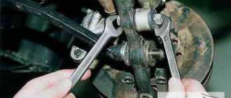
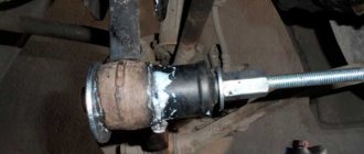
In the “Tens”, as well as the VAZ 2112, there are 16 valves and other models equipped with BOSCH 7.9.7 or January 7.2 systems, one M6 screw is installed in the head. From this screw the mass is taken to the ignition coils, and the mass is taken directly to the control model in the cabin. Typically, the mass is a welded stud mounted on the ECM bracket, particularly behind the center console, behind the left screen. In this case, the mass is transferred to the bracket through a pin, which is welded on the engine shield in the middle. It should also be noted that the nut on this stud is not usually tightened.
Control unit location
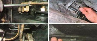
Now let's consider the location of the VAZ 2110 ECU. This device in the Ten is located under the center console, in its lower part, in particular, under the control panel. In order to gain access to the control module, you must remove the plastic panel on the passenger side, to do this you will have to use a Phillips screwdriver. Once you remove the cover, you will see many different wires, plugs, and safety devices. The controller itself is located behind them, it is screwed to the bar in a horizontal position.
The arrow indicates the location of the ECM module behind the center console
Typical malfunctions: their symptoms and causes
If the electronic engine management system malfunctions, this can lead to problems with the operation of the power unit. Unfortunately, ECU malfunctions in dozens of domestic cars are not uncommon, so the car owner should be aware of the main problems, as well as the reasons for their occurrence.
First, let's look at the symptoms of malfunctions:
- There is no connection with the diagnostic tester. If problems begin to appear in the operation of the engine, the car owner can diagnose the performance of the power unit using a tester or laptop. But if the ECU does not work, then when trying to contact the on-board computer, the car owner will see that there is no connection.
- The ECM does not receive signals about the operation of the injectors, ignition system, fuel pump, valve or idle speed sensor. There may also be no signals from other actuators.
- Another sign is the lack of response to the oxygen sensor, engine temperature controller, throttle position sensor and other controllers.
- Mechanical damage to the device can also be a sign of failure. Cracks may appear on the case as a result of strong mechanical impact; radio elements or conductors could burn out (the author of the video about the repair is Pavel Ksenon).
As for the reasons, malfunctions in the electronic control unit can occur as a result of:
- Unskilled intervention. This reason is one of the most common. If a car owner independently carries out electrical repairs or installs an anti-theft system, or entrusts this work to unqualified craftsmen, errors may be made in the process.
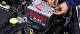
- A common problem is lighting a car battery from a vehicle with the engine running. When lighting the engine, the engines of both cars must be turned off, otherwise there is a risk of brain damage, this is important to remember.
- Another problem that does not occur so often is polarity confusion when connecting a car battery. If you confuse plus with minus, it can not only damage the control unit, but also damage the battery itself, which can lead to expensive repairs.
- The reason may be that the battery terminals are disconnected while the engine is running.
- Also, the control unit may fail as a result of turning on the starter unit with the power bus disconnected.
- The engine control system can be damaged if an electrode accidentally hits the sensor or vehicle wiring during welding work.
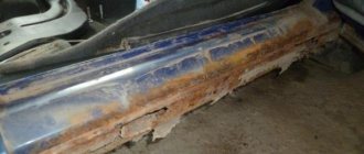
- One of the most serious problems is water getting into the ECU. If liquid gets into the device, the board itself may become covered.
- A break in the electrical circuit or a short circuit in the wiring.
- The cause may also be malfunctions in the high-voltage component of the ignition system. For example, a breakdown of the ECU can be caused by a failure of the coil, high-voltage cables, distribution mechanism, etc.
Pinout of contacts on the controller
Video “Why the ECM does not communicate during testing”
From the video below, you can find out why there may be no communication between the ECM and the laptop during diagnostics (the author of the video is the Billye espada channel).
Dear drivers, one of the reasons for poor engine starting is a burnout in the ECU of the power key gb10nb37lz.
But for some reason, many car owners immediately think that their Crankshaft Position Sensor has failed, I once had this problem. But this was also due to the fact that the wire from the sensor lay on ground and when the engine heated up, the braid melted and a short circuit occurred. In my blog: www.drive2.ru/l/6251079/
And so, our ignition diagram:
1 – battery 2 – ignition switch 3 – ignition relay 4 – spark plugs 5 – ignition module 6 – controller 7 – crankshaft position sensor 8 – master disk A – matching device
When the car does not start, most people immediately blame the crankshaft position sensor. Changing it they realize that it didn’t help. When checking the block, the wire does not give any result. The next steps are to install a new module, or this also does not give the computer anything. The car still won't start.
Everything is simple: the crankshaft sensor just has its own resistance, like the ignition module, by ringing it you can understand whether they are in good condition. Also don’t forget to check the fuse and main relay. Next, we check the spark plugs and armor wires to see if the retractor on the starter works (just put your hand on it, and if it doesn’t hit when starting, it means it’s working). During this check, you can understand what is wrong.
Checking the Crankshaft Position Sensor:
2. We quickly move the screwdriver blade close to the end of the sensor, while we observe voltage surges on the voltmeter.
Conclusion: The sensor is working.
Checking the DPKV circuit: With the ignition off, disconnect the engine management system wiring harness block from the crankshaft position sensor. We connect the tester probes to terminal “B” of the wiring harness block and engine ground.
Let's sum it up
Malfunctions of the VAZ-2110 heater control unit can lead to both incorrect functioning of the vehicle’s heating system and complete failure of the heater. During the cold season, this will affect not only a comfortable stay in the car, but also safe driving for the driver of the vehicle.
Repairing the stove control unit can be done on your own if you have basic knowledge of electronics, a desire to work and improve your comfort.
High-quality repairs and timely regular inspections of the unit before the onset of cold weather will help you save money on stove repair services at service centers and the purchase of expensive heating system elements.
Adjusting the stove controller
The manufacturing plant provides for heating the interior to the specified temperature in fifteen minutes with a deviation of up to two degrees. Use the controller knob to set a comfortable temperature in the car interior.
To check the proper functioning of the stove, use a regular mercury room thermometer. If after fifteen minutes the interior has not warmed up to the required temperature, the controller must be adjusted.
To do this, pull the heater control module back out and rotate the temperature regulator, first to the maximum value, then in the opposite direction. After carrying out such actions, install the unit in place and check the operation of the stove again.
At the same time, it is necessary to check the operation of the heater dampers. If there are extraneous sounds when switching temperature modes, then you need to check the condition of the dampers. If cold air flows well, but hot air hardly flows in, then the lower damper is faulty. If there is no normal flow of cold air but there is a good flow of hot air, there is a problem with the upper damper. The reason may be deformation of the dampers under the influence of air of different temperatures. In this case, it is better to replace the standard plastic dampers with aluminum analogues, which are more resistant to temperature changes.
After adjusting the controller, all heater elements are installed in their original places. Assembly is carried out in reverse order.
How to check the ignition of a VAZ 2110 yourself
As mentioned above, as part of ignition diagnostics, you should check the ignition module on the VAZ 2110, perform diagnostics of spark plugs, caps, and high-voltage wires. The main symptoms of malfunctions are not always associated with the ignition module, that is, you need to use the exclusion method.
To correctly determine the malfunction, it is necessary to check not only the module itself, but also other elements of the ignition system: spark plugs, caps, high-voltage wires.
Checking the spark plugs is as follows:
- unscrew the spark plugs, putting on the caps, place them on the cylinder head and crank the engine with the starter;
- if the spark on the spark plugs is not stable, replace the faulty parts with new or working ones;
- repeat the check of the new spark plugs already installed.
Please note that you cannot crank the engine with the starter with the high-voltage wires removed, as this may lead to a breakdown in the ignition module cover. Checking high-voltage wires and caps:
Checking high-voltage wires and caps:
- remove the caps, hold the wire contact through the insulator at a distance of 10-15 mm from the head;
- if the plate does not penetrate this distance, then the wires are damaged;
- check the wires for resistance (nominal resistance should be in the range from 7 to 10k ohms)
- if there are deviations, change the entire set of high-voltage wires;
You should also check the caps for breakdown. In any case, having excluded the remaining elements of the system from the list of faults, we proceed to checking the ignition module. To check it you need a multimeter and 15-20 minutes of free time.
You can perform the check yourself, knowing the sequence of work performed and the nominal value of the module. So, if there is a suspicion of a VAZ 2110 module, the check involves the following procedure:
- inspect the ignition module for chips and cracks (if any, the ignition module is immediately replaced without any checks);
- check the power supply and the presence of pulses coming from the computer (check the power supply between the engine ground and the central terminal (15) of the wire block connected to the module). The voltage when the ignition is on must be at least 12V;
- check the pulses coming from the electronic control unit on the wire block by installing one multimeter probe on the connector (15), the other first on the rightmost one, then on the leftmost one;
- having cranked the engine with the starter, use a multimeter to record short-term voltage surges (no pulses – the problem is in the ECU);
- check the resistance on the secondary windings of the coils by putting the multimeter in resistance measurement mode. At the high-voltage terminals of the module cover between terminals 2-3 and 1-4, the resistance should be within 0.5 ohms (if there is a discrepancy, the module is replaced);
- check the resistance on the secondary windings of the coil between contacts (15) and first the rightmost, then the leftmost terminal. The resistance should be 0.5 Ohm;
- check the module for a short circuit by setting the multimeter to ohmmeter mode (one probe of the device to the central terminal, the second to the metal body, the norm is no resistance);
- When the device detects any resistance, the module is changed.
Stories from our readers
“Fucking basin. "
Hi all! My name is Mikhail, now I’ll tell you a story about how I managed to exchange my two-wheeler for a 2010 Camry. It all started with the fact that I began to be wildly irritated by the breakdowns of the two-wheeler, it seemed like nothing serious was broken, but damn it, there were so many little things that really started to irritate me. This is where the idea arose that it was time to change the car to a foreign car. The choice fell on the melting Camry of the tenth years.
In December 2005, NPP Avtel released for spare parts (this was never supplied to the VAZ assembly line.) ECU “January 5.1.x” with modified hardware.
The next step in the fight for environmental friendliness of exhaust was the development, commissioned by AvtoVAZ OJSC, of a more modern unit that could meet more stringent toxicity and diagnostic standards Euro-2 and Euro-3, called MP7.0. In this modification, both the hardware and software were developed, the final calibration and fine-tuning of the systems was carried out by AvtoVAZ OJSC.
This family is also expanding and has already been supplemented with systems meeting Euro-3 standards for 8 and 16-valve engines of front-wheel drive vehicles, as well as for all-wheel drive vehicles VAZ-21214 and VAZ-2123 (Euro-2 and Euro-3 standards).
NPO Itelma has developed an ECU for use in VAZ cars, called VS 5.1. This is a fully functional analogue of the ECM January 5.1, that is, it uses the same harness, sensors and actuators. Modifications 2112-1411020-42 and 2111-1411020-62 are designed for Euro-2 standards and include an oxygen sensor, catalytic converter and adsorber; this family does not provide for P-83 standards for 2112 engines.
For VAZ 2111 and Russia-83 standards, only the ECM version VS 5.1 1411020-72 with simultaneous injection is produced. For “classics” with a volume of 1.45 liters. modification VS5.1 2104-1411020-02 is available, with DC (Euro-II) and without a detonation channel. These ECMs were discontinued in early 2005.
Controllers with software for 16 cells. engines under Euro-3 standards support the function of software switching of starting calibrations Europe/Russia from diagnostic equipment. This function, according to the developers, should make starting on low-quality gasoline easier. Default to .
The first batch of Lada Priora cars, which is a deep restyling of the “tenth” family, began rolling off the VAZ assembly line at the beginning of 2007. And also with a Bosch M7.9.7+ ECU (firmware B173DR01, “homemade” nameplate, pasted on top of the original one).
For the “classics”, ECU 21067-1411020-11(12) was developed for configuration without a knock sensor, with a Siemens-VDO mass air flow sensor. This modification is installed on 1.6-liter engines. And, as usual, the detonation channel elements are not installed in the block.
For this type of ECU, a complete software shutdown of the DC and adjustment of the CO content in the exhaust gases has been implemented, that is, a transfer to Russia-83 toxicity standards.
Frequent malfunctions of the VAZ electronic control unit
Considering that the controller is a complex electronic device, failure of the ECU cannot be ruled out. As a rule, the causes of ECU malfunction can be different, ranging from mechanical damage to software failures.
For example, a common cause of breakdowns is overheating or liquid ingress. As practice shows, on the Lada Samara the ECU is located near the heater radiator. It is not difficult to guess that a radiator leak and coolant entering the controller often disables this device.
In this case, the check engine light does not always light up on the panel, but the engine malfunctions. In such a situation, when no other causes have been identified, what is needed is not diagnostics of the engine and systems, but professional diagnostics of the car's ECU, which can only be performed by an experienced specialist. Often, after checking, the unit may need to be replaced, since ECU repair is often not recommended.
The concept of self-diagnosis mode. What are error codes and how to use them
We have already said earlier that the VAZ 2110 on-board computer greatly helps prevent problems that arise due to improper operation of the executive and control systems of your car when the “Check Engine” light comes on. All this is real, since the chip has an on-board self-diagnosis mode installed on the VAZ 2112 computer. The BC receives information from the ECU via the K-line and tells the motorist what’s wrong with his iron horse.
This is very important, since all engine systems on the VAZ-2110 injector type are controlled by the ECU and failures in its operation and the functioning of the main diagnostic systems can lead to failure of the entire vehicle, irrational fuel consumption and severe loss of internal combustion engine power. If you have a VAZ 2110 on-board computer, you just need to ask it what’s wrong with the car, and your “electronic” friend will immediately give out all the ins and outs
There is no need to call expensive specialists or spend a long time digging under the hood of the car - self-diagnostic systems can do all this for us.
Of course, the VAZ 2110 on-board computer tells us information about errors in encoded form. You won't see a text message telling you exactly what's wrong with your vehicle, just a digital fault code. The main reason for this approach is that the size of the on-board computer screen is very limited. But this is actually not a problem if you have a guide with decoding at hand (it can also be easily found on our website).
If your car is equipped with only a basic on-board computer VAZ-2110, located under the speedometer on the dashboard, then the self-diagnosis mode in it is started by simultaneously turning the ignition key and holding down the daily mileage reset button. Immediately after this, all the arrows on the dashboard should start “dancing” in front of you. By pressing the reset button twice, we switch from the firmware version, in fact, to error information
If your car is equipped with a luxury package, where the VAZ 2110 on-board computer is installed next to the SAUO unit (and AMK 211002), the self-diagnosis mode there is activated even easier by pressing the “clock” button in the time display mode. If an error message appears, you just need to connect the VAZ 2110 on-board computer to the diagnostic interface.
Setting up the AMK 211001 on-board computer
We set up the staff on-board computer on a VAZ 2110 using the example of a basic BC of a luxury configuration. Some useful tricks.
Undoubtedly, in order to fully cover all the capabilities of the on-board computer on the VAZ 2110, it is worth reading the operating instructions for it. We will consider only a short list of some useful functions that the standard on-board computer of the VAZ 2110 is capable of. For example, setting up a sensor responsible for the fuel level in the tank:
- 1. First of all, you need to completely empty the gasoline tank in your car. Next, you need to switch to the fuel selection mode by holding the first button from the top in the right row for several seconds. The on-board computer of the standard VAZ 2110 will display the number “0” on the display.
- 2. We switch to the testing mode by holding down the button with the image of the car for a second, about which the on-board computer on the VAZ 2112 will notify us with a short sound signal. The number “3” now lights up on the display.
- 3. Fill the gas tank with 3 liters. gasoline. After waiting for some time, press and hold the button with the image of the car again.
- 4. We continue to fill the tank with gasoline to its maximum capacity. The bookmaker will complete the thorification procedure itself and switch to standby mode.
- 5. It’s even easier to set up a BC for speeding alarms. To do this, you need to switch to the “medium speed” mode and again hold the upper right button for several seconds. The integer digital value is set using the “+” and “-” function keys on the instrument panel. We exit the speed setting mode in the same way as we entered it.
Error P0504
This malfunction is associated with an incorrect signal from the brake pedal switches. Most often, the cause of such a failure is a malfunction of the brake pedal position sensor, lack of proper adjustment, or a broken spring that is installed in this device. Procedure for checking and troubleshooting:
- We remove the sensor;
- Move the rod lock to the right position using a screwdriver;
- We use a multimeter with an ohmmeter function;
- On Largus, Vesta and Xray cars, contacts 3-4 should be closed and have a resistance close to zero. Contacts 1-2 are open and their resistance should tend to infinity.
- When you press the rod on contacts 3-4, the circuit opens, and on contacts 1-2 it closes. If this is not the case, then the sensor must be replaced.
- On Priora, Kalina, Granta, Niva cars, contacts 1-4 should be closed, and 2-3 open. When you press the rod, the situation is the opposite.
- Before reinstalling the sensor, move the rod to the left position.
Sensor locations in video:
Adjusting the brake pedal position sensor:
Any driver can carry out this procedure at home without a trip to a service station. The part has two nuts in its design. One of them is on top, and the second is on the bottom. The upper nut adjusts the pressure of the rod. First you need to release the lower one, and then tighten the upper one, thereby changing the gap of the element. You need to ensure that the rod is fully pressed and not partially pressed. After this, start the car and let it run for about 10 minutes to check if the error appears.
Video “No spark and blown fuse - repairing the ECU”
What to do if there is no spark and the fuses are constantly blowing - the video below shows the process of repairing the control controller in a garage (the author of the video is the Auto Practice channel).
I came across an article by McSystem. Actually, here it is below
In January - about Januarys. Again and in detail about the ECM-ECU masses
One of the rather serious problems affecting the stable operation of engines controlled by the January ECU (7.2, 7.2+, M73, 7.9.7) is the “mass problem” of the ECM. Moreover, the point is not so much in bad (or uncrimped) contacts and their fastenings, but rather in the rather incorrect wiring of the ECM harness itself. And the solution is not in “pulling a fancy cable (KG-25 or 50)” to the ECU. Therefore, this material will be devoted to a technically competent approach to solving this problem. What is described below is a kind of compilation, or an attempt to “chew” what has been published more than once, in particular on ChipTuner.ru, and to convey to readers the specifics of solving this problem. The articles by I.N. turned out to be the most complete and informative. Skrydlova, (aka Aktuator) “About the masses”, “MASS: AN UNEXHAUSTABLE SOURCE OF GLITCHES” “ONCE AGAIN ABOUT THE MASSES” ©Oleg Bratkov. Many years ago, having read and comprehended what was written, I implemented it on my typewriter. I completely agree with the conclusion of the author (aka Aktuator): “All the assurances of AVTOVAZ OJSC about improving the quality of electrical connections in manufactured vehicles are not worth a penny. In most cases, it is possible to achieve normal operation of the engine under the control of the ECM I 7.9.7 and January 7.2 only by carrying out additional, and not accepted by the manufacturer as a warranty, work to change the electrical circuit of the car.”
So, on to the topic! Classic ECM 21124 with ECU January 7.2(+) or M7.9.7 Electrical connection diagram of ECM EURO-2 M7.9.7, January 7.2 LADA 2110 with engine 21124. 21124-1411020-30, 21124-1411020-31.32
Fig. 1 ECM 21124 January 7.2, M7.9.7 Noticed, often described and characteristic problems - unstable idle speed, freezing speed, “jerking” of the engine at start and operation of the cooling fan, unreasonable jumps in the electrical parameters of the ECM during diagnostics. And this is not the entire list. And the whole problem is a rather incorrect wiring of the harness masses, not in relation to the body, but to the ECU. Therefore, in this article you will not see recommendations for tightening the “hoses” of additional mass to the ECU, due to its complete uselessness. This is not a newfangled “razmasovka” or “razminusovka”... Don’t get your hopes up!
The main idea voiced by the authors is that the wiring of the power lines of the ECU and fan and low-current sensor masses is fundamentally incorrect. Rice. 12
Fig.2 Ground connections of the ECM. S6, S7, S8
The sensors must be connected to the ground bus of the ECU board and not have contact with the body! There should be no flow of pulsed and direct currents of the ECU and IM in the sensor mass circuit. And the ECU is securely connected to the body. The rationale is to eliminate the influence of ECU currents (pulse and constant) and fan current on the reliability of sensor readings. Classic approach with data collection and processing systems! But not from AvtoVAZ designers, as usual... Now, in order
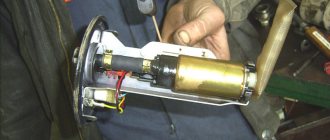
Checking the functionality of the idle speed sensor
You must identify the breakdown manually - there is no self-diagnosis. The idle speed regulator of the VAZ 2110 is located in the intake after the valve (throttle body).
First, analyze the electrical part with a multimeter:
- The pinout of the IAC VAZ 2110 is being studied (available in the product instructions or on the Internet).
- They check whether the sensor is powered normally, for which it is disconnected and the block is removed.
- They take measurements of the two outer terminals on block A and D: Turn on the ignition, turn the multimeter to “continuity”, the black probe to ground (on the body itself) of the internal combustion engine, touch the positive (red) contacts one by one. A value within 12 V is normal. If not, the circuit is broken, the ECU is broken, the battery is discharged. This means we check the integrity (contacts, wires), the ECU (at pins 4 and 54 the norm is also 12 V), and the battery. If they are working properly, the problem is in the valve;
PRINCIPLE OF AIR FLOW
Heater control unit for VAZ 2110
In winter, adjustable flaps direct the main flow to the windshield heating:
- Air is supplied through deflectors to the side windows and into the center of the cabin.
- The air flow is distributed over two pairs of deflectors for heating those sitting in front.
- The distribution also goes through a tunnel in the floor to the rear seats, as well as additionally through two air ducts under the front seats.