In theory, to fill the cylinder with a combustible mixture and release exhaust gases, the valves must open exactly at top or bottom dead centers. In practice, this has to be done in advance. Moreover, at different engine speeds, the open state time should be different. But the timing and height of valve lift are determined once and for all by the shape of the camshaft lobes, representing a compromise between high torque at low rpm and high power at high rpm. To optimize the filling and cleaning of engine cylinders in different operating modes, variable valve timing systems were created.
FIXED PHASES
The valve timing is usually called the opening and closing moments of the intake and exhaust valves, expressed in degrees of rotation of the crankshaft relative to TDC and BDC. In graphical expression, the opening and closing period is usually shown as a diagram.
If we are talking about phases, then the following can be changed:
- the moment when the intake and exhaust valves begin to open;
- duration of stay in open state;
- lift height (the amount by which the valve lowers).
For now, most engines have fixed valve timing (but the trend is rapidly changing). This means that the parameters described above are determined only by the shape of the camshaft cam. The disadvantage of this design solution is that the shape of the cams calculated by the designers for engine operation will be optimal only in a narrow speed range. Civilian engines are designed in such a way that the valve timing corresponds to normal operating conditions of the vehicle. After all, if you make an engine that will run very well “from the bottom,” then at above-average speeds the torque, as well as the peak power, will be too low. It is this problem that the variable valve timing system solves.
Conclusions about motor phase control systems
VVT phase regulators as systems:
- Simple
- Effective
- Providing many benefits and advantages with a minimum of disadvantages.
For them to work reliably and without problems: they do not require additional conditions and measures - they are exactly the same as those necessary for high-resource, confident and problem-free operation of engines in difficult Russian conditions. If you take care of your car, it will respond with the infallibility of its work, giving you the thrill of owning it for many years and hundreds of thousands of kilometers. Remember the very positive proverb of our driver ancestors: “A car loves: affection, cleanliness and lubrication.” Relevant – even today!
PRINCIPLE OF OPERATION VVT
The essence of the VVT system is to adjust the valve opening phases in real time, focusing on the current operating mode of the engine. Depending on the design features of each system, this is implemented in several ways:
- turning the camshaft relative to the camshaft gear;
- activation of cams at certain speeds, the shape of which is suitable for power modes;
- changing the valve lift height.
The most widespread are systems in which phase adjustment is carried out by changing the angular position of the camshaft relative to the gear. Despite the fact that the operation of different systems is based on a similar principle, many automakers use individual designations.
- Renault – Variable Cam Phases ( VCP ).
- BMW - VANOS . Like most automakers, initially only the intake camshaft was equipped with such a system. A system in which hydraulic couplings for variable valve timing are installed on the exhaust camshaft is called Double VANOS .
- Toyota - Variable Valve Timing with intelligence ( VVT-i ). As is the case with BMW, the presence of a system on the intake and exhaust camshafts is called Dual VVT .
- Honda - Variable Timing Control ( VTC ).
- Volkswagen - chose the international name - Variable Valve Timing ( VVT ).
- Hyundai , KIA , Volvo , GM - Continuous Variable Valve Timing ( CVVT ).
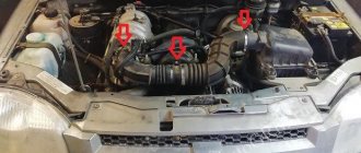
Tools for setting valve timing
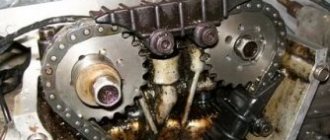
In order for the engine to operate without interruption, it is important to set the timing timing correctly and install the camshafts in the desired position relative to the crankshaft. On all engines, the shafts are aligned according to marks, and a lot depends on the accuracy of the installation. If the shafts are not aligned correctly, various problems arise:
- the engine is unstable at idle;
- The internal combustion engine does not develop power;
- There are shots in the muffler and popping noises in the intake manifold.
If the marks are wrong by a few teeth, it is possible that the valves may bend and the engine will not start.
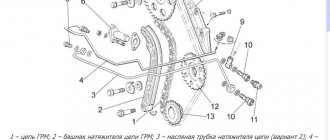
On some models of power units, special devices have been developed for setting valve timing. In particular, for engines of the ZMZ-406/406/409 family there is a special template with which the camshaft position angles are measured. The template can be used to check the existing angles, and if they are incorrect, the shafts should be reinstalled. The device for 406 motors is a set consisting of three elements:
- two protractors (for the right and left shaft, they are different);
- protractor
When the crankshaft is set at TDC of the 1st cylinder, the camshaft cams should protrude above the upper plane of the cylinder head at an angle of 19-20º with an error of ± 2.4°, and the intake cam should be slightly higher than the exhaust camshaft cam.
There are also special devices for installing camshafts on BMW engines of the M56/ M54/ M52 models. The kit for installing the valve timing of the internal combustion engine of the BVM includes:
- torque wrench with extension;
- adjustment plate for double VANOS system;
- pins for fixing the flywheel;
- sleeve with spindle for tensioning the primary chain;
- a device for tensioning the secondary chain, as well as for blocking the tensioner plunger;
- camshaft retainer.
HOW PHASES AFFECT ENGINE OPERATION
The behavior of gases inside the internal combustion engine changes depending on the operating mode of the engine. For example, at idle speed the pistons move much lower than in operating mode at maximum speed. Accordingly, fluctuations in the gas environment in the intake and exhaust manifolds significantly depend on the operating point of the engine. The mentioned oscillations can be both beneficial, creating a resonant boost, and harmful - parasitic oscillations, stagnation. That is why the speed and efficiency of filling the cylinders at different operating points of the engine differ significantly.
At low speeds, maximum cylinder filling will ensure late opening of the exhaust valve and early closing of the intake valve. In this case, valve overlap (the position in which the exhaust and intake valves are open at the same time) is minimal, so that the remaining exhaust gases in the cylinder are not forced back into the intake. It is precisely because of the wide-phase (“overhead”) camshafts on forced engines that it is often necessary to set higher idle speeds.
At high speeds, to get maximum performance from the engine, the phases must be as wide as possible, since the pistons will pump much more air per unit time. In this case, valve overlap will have a positive effect on the purging of the cylinders (the release of remaining exhaust gases) and subsequent filling.
That is why installing a system that allows you to adjust the valve timing, and in some systems, the valve lift height, to the engine operating mode, makes the engine more flexible, more powerful, more economical and at the same time friendlier to the environment.
Honda engineers are considered to be the pioneers of the variable valve timing system. They implemented the VTEC mechanism in the Integra model, which made it possible to add 40 to 60 hp to the 1.6 liter engine.
Service
Since the system includes a filter, it is recommended to change it. The average replacement interval is 30 thousand kilometers. It is also possible to clean the old filter. A car enthusiast can easily cope with this procedure on his own. The main difficulty will be finding a place to install the filter itself. Most designers place it in the oil line from the pump to the solenoid valve. After dismantling and carefully cleaning the CVVT filter, it is necessary to inspect it. The main condition is the integrity of the mesh and body. It must be remembered that the filter is quite fragile.
Without a doubt, the CVVT system is aimed at improving engine performance in all operating modes. Due to the presence of a system for advancing and retarding the opening of the intake valves, the engine has better fuel efficiency and reduced emissions of harmful substances. It also allows you to lower the idle speed without reducing the stability of operation. Therefore, this system is used by all leading automakers without exception.
SYSTEMS WITH DIFFERENT CAM SHAPE
Such systems were the first to appear - Honda engineers added a third to the two cams that control the opening of the valves. He had a higher profile. At low speeds the low profile cams operated, and at high speeds the high profile cams came into action. Various automakers soon released such gas distribution systems, but under different names:
- HONDA - Variable Valve Timing and Lift Electronic Control ( VTEC ). If an engine uses both VTEC and VVT at the same time, then such a system is abbreviated i-VTEC .
- BMW - VANOS .
- AUDI - Valvelift System.
- TOYOTA - Variable Valve Timing and Lift with intelligence from Toyota ( VVTL-i ).
- MITSUBISHI - Mitsubishi Innovative Valve timing Electronic Control ( MIVEC ).
Why is valve actuation delayed and advanced?
To improve the filling of the cylinders, as well as to ensure more intensive cleaning of exhaust gases, the valves operate not at the moment the piston reaches the dead points, but with a slight advance or delay. Thus, the intake valve opens until the piston passes TDC (from 5° to 30°). This allows for more intensive injection of fresh charge into the combustion chamber. In turn, the closing of the intake valve occurs with a delay (after the piston has reached bottom dead center), which allows the cylinder to continue filling with fuel due to inertial forces, the so-called inertial boost.
The exhaust valve also opens early (from 40° to 80°) until the piston reaches BDC, which allows the majority of the exhaust gases to escape under its own pressure. Closing of the exhaust valve, on the contrary, occurs with a delay (after the piston passes the top dead center), which allows inertial forces to continue removing exhaust gases from the cylinder cavity and makes its cleaning more efficient.
The stage of engine operation in which both valves are open simultaneously is called valve overlap. As a rule, the amount of overlap is about 10°. Moreover, since the overlap duration is very short and the valve opening is insignificant, no leakage occurs
This is a fairly favorable stage for filling and cleaning the cylinders, which is especially important at high speeds
At the beginning of the intake valve opening, the current pressure level in the combustion chamber is higher than atmospheric pressure. As a result, the exhaust gases move very quickly towards the exhaust valve. When the engine switches to the intake stroke, a high vacuum will be established in the chamber, the exhaust valve will close completely, and the intake valve will open to a cross-sectional area sufficient for intensive filling of the cylinder.
DEVICE, PRINCIPLE OF OPERATION VVT
The angular displacement of the camshaft is controlled by a phase shifter, which is a fluid coupling, the operation of which is controlled by the engine ECU.
Structurally, the phase shifter consists of a rotor, which is connected to the camshaft, and a housing, the outer part of which is the camshaft gear. Between the hydraulically controlled clutch housing and the rotor there are cavities filled with oil. Filling them leads to movement of the rotor, and, consequently, displacement of the camshaft relative to the gear. Oil is supplied to the cavity through special channels. The amount of oil entering through the channels is adjusted by an electro-hydraulic distributor. The distributor is a conventional solenoid valve, which is controlled by the ECU via a PWM signal. It is the PWM signal that makes it possible to smoothly change the valve timing.
The control system, in the form of the engine ECU, uses signals from the following sensors:
- DPKV (crankshaft rotation speed is calculated);
- DPRV;
- TPDZ;
- DMRV;
- DTOZH.
3-stage VTEC-E
What color and how are the neutral, phase and ground wires designated in electrical engineering?
The 3-stage SOHC VTEC gas distribution mechanism is a combination of the SOHC VTEC and SOHC VTEC-E systems. Unlike all the systems described above, this system has not two operating modes, but three.
At the first stage, when the crankshaft rotation speed does not exceed ~2500 rpm, the rocker (rocker arm) of the first and second ones operate independently. The almost round cam of the second valve actuates the second valve through the rocker, i.e. in fact, the intake process is carried out through the first valve, while the second valve is only slightly opened to avoid the accumulation of fuel above it. The cam of the second valve runs idle. In the second stage, starting at approximately 2500 rpm, oil supplied through a passage in the camshaft presses on the timing rod, which connects the rockers of the first and second valves, ensuring that both intake valves operate synchronously according to the cam profile of the first valve. The remaining cams work idle. In the third mode, the oil still presses on the rod in a position where synchronous operation of both valves is ensured, while, starting from ~4500 rpm, oil begins to flow through the channel into the other cavity and put pressure on the pin, ensuring the transfer of valve control from a third cam with a larger profile, providing greater lift height.
In the low speed zone, the system ensures economical engine operation with a lean fuel-air mixture. In this case, only one of the intake valves is used. At medium speeds, the second valve comes into operation, but the valve timing and valve lift do not change. The engine in this case produces high torque. At high speeds, both valves are controlled by one central cam, which is responsible for extracting maximum power from the engine.
The next round of development
Stepwise changes in the opening duration and valve lift height make it possible not only to change the valve timing, but also to almost completely remove the function of regulating the load on the engine from the throttle valve. We are talking primarily about the Valvetronic system from BMW. It was BMW specialists who first achieved such results. Currently, similar developments are available: Toyota (Valvematic), Nissan (VVEL), Fiat (MultiAir), Peugeot (VTI).
A throttle valve open to a small angle creates significant resistance to air flow. As a result, part of the energy obtained from the combustion of the air-fuel mixture is spent on overcoming pumping losses, which negatively affects the power and economics of the vehicle.
1 - Servomotor; 2 - Worm shaft; 3 - Return spring; 4 - Rocker block; 5 - Intake camshaft; 6 - Ramp; 7 - Hydraulic valve lash compensation system (HVA) on the intake side; 8 - Inlet valve; 9 - Exhaust valve; 10 - Roller pusher lever on the exhaust side; 11 - Hydraulic valve clearance compensation system (HVA) on the exhaust side; 12 - Roller pusher lever on the intake side; 13 — Intermediate lever; 14 - Eccentric shaft; 15 - Worm wheel; 16 - Exhaust camshaft;
In the Valvetronic system, the amount of air entering the cylinders is controlled by the degree of lift and the duration of valve opening. This was achieved by introducing an eccentric shaft and an intermediate lever into the design. The lever is connected by a worm gear to a servo drive, which is controlled by the ECU. Changes in the position of the intermediate lever shift the effect of the rocker arm toward greater or lesser valve opening. The operating principle is shown in more detail in the video.
The combination of phase shifters on the shafts, stepless stroke adjustment and duration of valve opening allows, according to engineers, a 10-15% reduction in fuel consumption and a similar increase in torque.
What about our VAZs?
As I already wrote above, old engines (and VAZ is no exception here) simply had an ordinary sprocket, on which either a chain or a timing belt was put on. Now we are not talking about new ones, but about old ones.
As you might guess, they had average phase values (and, accordingly, overlap).
Using the factory method, the phases were practically not adjusted in any way; I am now silent about adjusting the valves. Also, sports camshafts will not be discussed here (this is a slightly different topic).
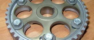
However, our craftsmen, in the garage and various tuning studios, installed the so-called “split camshaft gears”. What it is? This is a gear that consists of two parts: The inner part is connected to the camshaft.
The outer part - which connects to the chain - timing belt.
They are fastened together with bolts; the holes for these bolts have a small stroke. That is, these parts can rotate slightly (at a small angle) relative to each other. In this way, it was possible to change the angle and, using the selection method, set the required power, consumption and operation of the motor.
BUT this is rather an exception to the rule, and now modern engines, say, on LADA VESTA, already have phase shifters (so there are no problems with correct valve overlap).
Now we are watching the video version
I’ll end here, I think my materials were useful to you. Subscribe to the channel, read our AUTO SITE
63,50
Similar news
Hydraulic compensators: what are they and why do they knock?
Iridium spark plugs. Reviews, service life, pros and cons –.
Bi-turbo (Bi-Turbo) and Twin-turbo (Twin-Turbo), double supercharging – .
Refusal from timing belt
Now there are developments in which rotating timing elements are completely absent: such as the camshaft and the drive belt (chain), which significantly reduces friction losses. A system of electromagnetic solenoids allows you to control the operation of the valves. Each valve is provided with a separate solenoid, the operation of which is controlled by the control system.
Author: Sergey PETROV
The gas distribution mechanism (GRM) serves to ensure the timely supply of air or a combustible mixture to the engine cylinders (depending on the type of engine) and the release of exhaust gases from the cylinders. Let's figure out why it is necessary to change the timing phases.
All engine operating modes have their own optimal values for the duration of valve opening and closing. Thanks to automatic control of the gas distribution mechanism, it is possible to increase power and torque in almost all engine operating modes and reduce the toxicity of exhaust gases without the use of other design solutions.
Achieved results
Late closing of intake valves
(eng. late intake valve closing, LIVC). The first implementations of variable valve timing were systems that allowed the valve to be left open longer than in an engine not equipped with such a system. The result was the effect of pushing air out of the cylinder and into the intake manifold during the compression cycle. The air displaced from the cylinder increases the pressure in the intake manifold, as a result of which the next time the intake valve opens, air will be supplied to the cylinder at higher pressure. As a result of the introduction of late closing of exhaust valves, a reduction in losses in the intake tract of up to 40% is achieved, as well as a reduction in nitrogen oxide (NOx) emissions by up to 24%. Maximum engine torque is reduced by approximately 1% and hydrocarbon emissions remain unchanged.
Early closing of intake valves
(eng. early intake valve closing, EIVC). Another way to reduce losses in the intake tract, applicable at low engine speeds, is to create a high vacuum in the intake manifold using early closing of the intake valves. To achieve this, the intake valves must close during the intake cycle. At low load, the engine's need for the fuel-air mixture is small, but the requirements for filling the cylinders with it are quite high, which can be achieved by introducing early closing of the intake valves. Studies have shown that on engines with early closing of the intake valves, there is a reduction in losses in the intake tract by up to 40%, as well as an increase in efficiency by up to 7%. There is also a reduction in nitrogen oxide emissions of up to 24% in part-load modes. A possible negative side of introducing early closing of the intake valves is a significant decrease in the temperature in the combustion chamber, which can cause an increase in hydrocarbon emissions.
Early opening of intake valves
(eng. early intake valve opening). Opening the intake valves earlier is a way to significantly reduce emissions. A traditional engine uses a process known as valve overlap to control cylinder temperatures. When the intake valves open early, part of the exhaust gases flowing through the intake valve enters the intake manifold, where it is quickly cooled. Upon intake, the inert exhaust gases will largely fill the cylinder, resulting in a reduction in cylinder temperature and a reduction in nitrogen oxide emissions. Also, early opening of the intake valves improves volumetric efficiency since the volume of exhaust gases emitted is reduced during the exhaust cycle.
Early and late closing of exhaust valves
(eng. early/late exhaust valve closing). The introduction of these systems makes it possible to achieve a reduction in toxicity. In a traditional engine, during the exhaust cycle, the movement of the piston pushes the exhaust gases into the exhaust manifold and then into the exhaust system. By early and late closing of the exhaust valves it is possible to control the volume of exhaust gases remaining in the cylinder. By leaving the valve open longer than usual, it is more completely purified from exhaust gases and the cylinder is filled with a larger volume of fresh fuel-air mixture. When the exhaust valves close early, more exhaust gases remain in the cylinder, resulting in increased efficiency. The system allows the engine to maintain efficiency in all operating modes.
How the phases move
Different manufacturers have different designs of such systems. Some change the valve lift time, others change the lift height, and still others change both. Variable timing systems can be installed on the intake valves only or on both intake and exhaust valves. Currently, three methods of changing valve timing are used.
- The first method is to rotate the camshaft in the direction of rotation as the engine speed increases. This ensures earlier opening of the valves. The main part of such systems is a phase shifter (another name is a hydraulically controlled clutch). It is a rotor mounted in a camshaft pulley, between which there are cavities. These cavities, upon a signal from the engine controller through a solenoid valve, are filled with oil, which causes the camshaft to rotate. The angle of rotation depends on which cavity is filled. In most cases, the phase shifter is installed only on the intake camshaft; on some systems, it is also installed on the exhaust camshaft. VANOS and Double VANOS systems from BMW, VVT-i and Dual VVT-i(Variable Valve Timing with intelligence) from Toyota, VVT(Variable Valve Timing) from Volkswagen, VTC(Variable Timing Control) from Honda, CVVT( Continuous Variable Valve Timing) from Hyundai, Kia, Volvo, General Motors, VCP (Variable Cam Phases) from Renault.
- The second method is to use cams of different profiles in different operating modes. At low speeds, cams are used that provide “narrow” phases, that is, low lift height and valve opening time. As the speed increases, at the command of the control unit, a switch to “wide-phase” cams occurs. Thus, the phases change in steps, and not smoothly, as in the previous system. But, in addition to the phases, the valve lift height is also adjustable. Multi-profile cams are used in their systems: VTEC (Variable Valve Timing and Lift Electronic Control) from Honda, VVTL-i (Variable Valve Timing and Lift with intelligence) from Toyota, MIVEC (Mitsubishi Innovative Valve timing Electronic Control) from Mitsubishi.
- The third , the most advanced group of systems, smoothly regulates the valve lift height . The main advantage of such systems is that they eliminate the need for an intake throttle valve. This significantly reduces pumping losses and fuel consumption. For the first time such a system called Valvetronic was used by BMW. In it, between the camshaft and the valve, there is an additional lever, one end of which presses on the valve rocker arm, and the second is connected to the eccentric shaft. By turning this shaft using an electric motor, the control system thereby changes the tilt of the lever and its arm. Increasing the shoulder leads to an increase in valve lift and the amount of air entering the cylinders. The lifting height is adjustable from 0.5 to 12 mm.
Following BMW, similar systems were created by Valvematic from Toyota, VEL (Variable Valve Event and Lift System) from Nissan, MultiAir from Fiat, VTI (Variable Valve and Timing Injection) from Peugeot.
MultiAir system uses a single camshaft that drives both the intake and exhaust valves. But if the exhaust valves are mechanically controlled by cams, then the influence from the cams is transmitted to the intake valves through a special electro-hydraulic system. This is where the novelty lies. The intake cams press on the pistons, and they, through an electromagnetic valve, transmit force to the working hydraulic cylinders, which already act on the intake valves. The main unit is the valve that regulates the pressure in the system. It has only two positions: open and closed. If it is open, there is no pressure in the system and no force is transmitted to the valve. Therefore, by controlling the moment and duration of opening of the solenoid valve during the time the cam acts on the piston, you can achieve any algorithm for opening the intake valves. This means that the phase width can be smoothly adjusted from 0 to 100%. The maximum phase width is determined by the profile of the intake camshaft cam.
What does all of the above have to do with ecology? Variable valve timing systems, optimizing the fuel combustion process, thereby reduce fuel consumption and, therefore, the amount of harmful emissions.
Possible problems and solutions
- Engine oil for engines with variable valve timing must strictly comply with the approval or standards of the automaker. Example: in the lubrication system of an “atmospheric” gasoline EW10A, it is prescribed to use Total Quartz 9000 5W-40 or approved PSA B71 2296. The fact is that the correct operation of the phase shifter, namely, displacement by a certain angle at a given speed and load, is directly “tied up” » on viscosity and oil pressure. If it turns out to be more fluid or too viscous, the system’s functioning algorithm will be disrupted, which will worsen engine performance and can subsequently lead to a large number of problems. Therefore, do not “buy” into advertising statements about the “phenomenal benefits” of the products of some fuel and lubricants manufacturers - expectations of a miracle can turn into a shameful fiasco and a big loss of money.
- Saving on the quality of engine oil will also end in failure. Low-quality, counterfeit and surrogate “slurries” will inevitably lead to abundant deposits of wear and oxidation products in the stator chambers of the VVT coupling (there are more than enough places for dirt and debris to accumulate in them). Scores will appear on the friction surfaces. The wear process will become an avalanche. After some time, the phase regulator will begin to “mope.” If this is not “cured” in time, the coupling will jam, after which a long and expensive repair may be required. To prevent this from happening, use engine oil only as prescribed by the manufacturer, change it at the required intervals, and use only those fuels and lubricants of which you are 100% sure of their high quality!
- couplings are just as reliable as “regular” timing belt pulleys and timing chain sprockets. However, even with high mileage they require replacement due to natural wear and tear. Here, too, lurks a potential “time bomb”: on the market there are a large number of fakes and counterfeits from the “Heavenly Empire” made by handicraft methods, because VVT couplings are, although “long-lasting” products, but by no means cheap. Therefore, if replacement is still required, use only “original” or “branded” products from reputable manufacturers. Example: some redneck-minded owners of Peugeot and Citroen, when it is necessary to replace phase shifters on PSA EW7A/10A/12A engines, completely cross out their undeniable durability by using Chinese VVT couplings from Baificar instead of standard Japanese Denso or INA. Result: 30-40,000 km after replacement, they begin to “rattle”, leak oil, the engines run unevenly and refuse to start in winter, while the “original” from Denso and INA work reliably and do not cause problems for 200-300 000 km.
- VVT couplings, be sure to replace all associated rubber gaskets, seals, and seals. After all, phase regulators: units that change “once and for all,” because If there is a mistake or miserly economy “on matches”, to fix the problem you will inevitably have to disassemble everything again and adjust it again and at great expense. Therefore, it is much more profitable to carry out the entire, comprehensive set of component replacements during one act, even if they seem intact and functional, but this is prescribed by technical regulations or repair and maintenance manuals.
- Rubber rubber and gaskets , when replacing phase shifters, of course, must also be from reputable manufacturers or original. When purchasing them, preference should be given only to brands known for their quality and not chase low prices (there are plenty of fakes here too). If you are not an “expert” in this matter, we recommend products – Elring, Febi, Glaser, Goetze, SWAG, Victor Reinz, provided that the purchased product is genuine and purchased from an official dealer of these brands (you can find out on the manufacturer’s website).
- Work on servicing and replacing VVT should only be carried out at specialized service stations by the hands of experienced craftsmen. It will be necessary to use a certain amount of special tools (for some German and Japanese brands, this operation may require up to a dozen special devices!), which are not sold even in reputable auto parts stores, and once in your hands, they require experience and professional use skills. “Improved means” and “it’s not the gods who burn the pots” are inappropriate in this matter - in the event of even an innocent mistake, everything can end in a major overhaul of the engine. The reason for all this is the need to maintain pinpoint accuracy of the work performed and strict adherence to technical regulations, regardless of the brand and degree of complexity of the engine.
- Computer diagnostics of VVT on modern cars does not cause problems. The parameters of its operation are recorded by several sensors, and the operation of the control valve(s) is managed by a separate computer or ECU program. Moreover, testing only in rare cases requires a special dealer diagnostic complex - in the vast majority of cases it is possible to “read” information about the performance of the phase shifter using “unofficial” test computers. The main thing is that the specialist is experienced and understands the essence of VVT.
- Phase control valve can cause interruptions in engine operation and jumps in its speed. Often this is not the cause, but a consequence of the above problems. The consequences are:
- The spool rod is covered with an excessive amount of deposits and jams;
- Too much debris has settled on the protective nets and their permeability has decreased;
- Due to the large amount of metal “powder”, wear increased the gaps, the tightness was broken, and axial “beating” occurred.
The influence of external influences cannot be ignored:
- Oxidation of VVT valve electrical contacts;
- Natural aging of the insulation of the solenoid coils due to external (if, as a result of tuning, some hot element is installed next to it) or internal (when the housing is covered with a layer of dust or dry dirt, playing the role of a heat-insulating “fur coat”) overheating;
- Mechanical damage caused accidentally and/or unnoticeably during ICE maintenance.
Washing the valve in powerful solvents in order to restore its functionality sometimes helps for a short time, but this does not solve the main problem: if it does not work correctly, especially if it is jammed - in order not to waste a lot of unnecessary time and extra money, it is better to replace it with a new one.
9. Flushing the VVT should only be done after it has been dismantled. Attempts to do this by adding “miracle” detergent additives to the oil are doomed to failure. You need to understand that if the phase regulator is dirty inside, then the amount of slag and deposits in the oil system is no less large. During the dissolution process, heaps of debris can rush through the channels and settle right in the phase shifter chambers, thereby further worsening the situation.
If the coupling is dismantled and immersed in a bath of powerful solvent (even white spirit will do), then its functionality can often be restored. Of course, after such a “bath” it should be additionally and thoroughly washed from the inside with streams of solvent injected through the appropriate channels using special syringes or douches. It will take a fair amount of time - all movements must occur without jamming. This method allows you to free jammed locking pins, clamps and other moving elements of the clutch mechanism. Many of them will have to be pressed using a handy tool - use suitable plastic or wooden sticks for this, which will not scratch the very thin and delicate surfaces of the phase shifters.
However, the effect of such measures may be zero. The reason is that in an environment of accumulating contaminants, the coupling has to work for too long, and by the time it jams, all its internal working surfaces may have supercritical wear. Having dissolved all the “adversaries” and brought the phase regulator into seemingly working condition, the size of its gaps and axial beatings can make its subsequent normal operation impossible. If this is not noticed in time, you can cause fatal damage to the engine.
We dare not deny the effectiveness of VVT clutch flushing, just as we cannot argue with the “miracle of the last straw”. At the same time, based on experience, arguments and facts, it is too often and excessively regularly necessary to state that the purchase and installation of a new VVT clutch to replace a worn one turns out to be tens of times more profitable in all respects than attempts to revive a failed device.