The VAZ-2109 car was produced at AvtoVAZ from 1987 to 1997. Years of production 21099: 1990-2004 - in Russia, 2004-2011 - in Ukraine. Here are colored wiring diagrams (for the injector and carburetor) with a description of all the elements for various modifications. The information is intended for self-repair of cars. Electrical circuits are divided into several blocks for ease of viewing via a computer or smartphone; there are also circuits in the form of a single picture with a description of the elements - for printing on a printer.
Like the entire car, its electrical equipment was at an average level, so owners of Nines should know the wiring diagram thoroughly for routine repairs with their own hands.
How to install a Europanel on a VAZ 2109
Task: install a Europanel on a VAZ 2109 carburetor
What is needed for this:
1.Euro-torpedo 2. Instrument panel 3. Wiring under the torpedo 4. Fuse block 2114 (it has 9 relays)
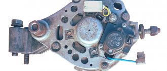
2114-3722010-60, as in the picture
5) Speed sensor (since there used to be a cable)—the sensor needs to be taken “6 pulse turn”
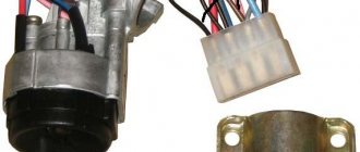
6) Steering column 2114 (with adjustment) 7) Wires that will come from the speed sensor 8) Cables from the VAZ 2114 stove, because old short ones 9) A pair of 4-pin relays 10) Current control 11) Ignition switch with 14k
Disassembly And so you removed the top, first we take out all the rubbish, rubbish, etc. from the car, then we climb under the column, we see the bolts for the column, you can remove it (I removed it because I made a Shumka of the whole muzzle, and there is more room without it)
Wiring
So we removed everything, we climb to the CY (mounting block), pull out all the pads from it, open the hood, also pull out all the pads from the CY and immediately put the new CY, all the pads (the things that were in the CY) back in their places. At the same moment, a beep will sound and the fan will start working, this can be solved, but first, so as not to heat your head, pull out the jumpers from the CY that stand in place of the fan relay and the signal.
We turn it on - there is no reaction, but on the tidy a couple of lamps work like a “handbrake” brick, etc. It’s all about the chip under the relay (4 contacts) there are 4 wires, 2 power (thick) 2 minuses (thin)
We need to connect the POWER wires to each other (these are blue-red and red) It should start. If not, then you have mixed up the chips, there are two of them on top of the other, you need to install a relay so that the heater turns, etc., work. (Or the wiring is not the same as mine) That is, we put a 4-pin relay on a chip with 4 wires
Everything should work. So the car starts, the heater turns the feet, etc., and all the buttons should work (hazard lights, heated glass)
Wiring, devices
The temperature on your dashboard should work, if not then you did something wrong or look at the diagrams (there will be some at the end) everything worked for me. So this list is what didn't show me at all, or didn't work properly
1) FLS (fuel level sensor) 2) Brake fluid sensor 3) Fan operation 4) Speed sensor 5) Tachometer 6) Horn
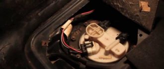
1) FLS (fuel level sensor) Take the red block that is inserted into the dashboard, find 4 pins there (pins in the photo below),
we cut it off and extend it to the pink wire on the block W/X9, depending on who you are, Ш9 pin 6, connect it and everything works.
2) Brake fluid sensor Here you only need to connect the black wire (at the barrel where the sensor is) to positive, instead of negative, we connect this black wire to (+) from the reverse sensor. The pictures show which wires.
black it to + to the back move black which goes to the brake
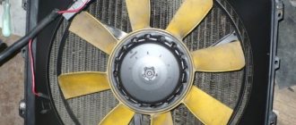
3) Fan operation I made the fan work regardless of the ignition position We will need - 4-pin relay - Wires: “+” battery to the relay - Relay block - Also a 20A fuse as in the photo According to the diagram, everything is simple)
need perdohr 20A
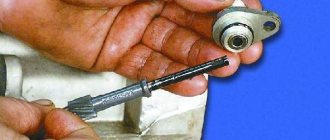
4) Speed sensor
We need a speed sensor “6 improtation” 2114, I have 3 wires coming out of it 1(+) 2(Signal) 3(-)
So 3. minus the ground on the body) 2. we connect this signal to the tidy (red block number 5 as marked in the picture) 1. plus to constant plus
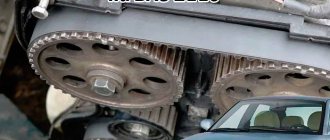
5) Tachometer We simply connect the brown wire directly from the coil (ignition bobbin) to the white block in the device to cell 3, cell 2 is also a tachometer but it is low-voltage for the brain (counting cells according to the normal scheme)
6) Sound signal, just take a 4-pin relay and insert it instead of a jumper)
Result : installation of the Europanel on the VAZ 2109 carburetor is completed.
Installation of sound signals from Volga on VAZ 2108
Many VAZ 2108 owners are not satisfied with the sound of their car’s standard horn. An excellent replacement for the standard one
How to connect and install
It is recommended to install and configure any musical device on the VAZ-2114 in accordance with generally accepted rules. Only in this case will the equipment work efficiently and perform all its functions.
Are you a car driver?! Then you can take this simple test and find out. Go to test »
Connection
To connect a radio to a VAZ-2114, just familiarize yourself with the procedure provided for any similar model (2115, 2109). The only difference will be in the location of one or another wire.
Connect the radio using this method:
- Connect the musical equipment connector to the positive and negative poles of the power source (battery). In this case, the cigarette lighter plug can be used for switching.
- Remove the cables from the speakers and connect them to the corresponding outputs on the device plug.
- As soon as the wiring is connected, all potentially dangerous places are isolated using special tape. You can additionally protect the cable from accidental contact and the negative effects of moisture by using a corrugated tube.
- An antenna is installed on the inside of the windshield or roof of the vehicle.
- The cable running from it to the dashboard is laid under various parts of the car's interior trim.
- The wire is connected to the radio directly or through an adapter.
Scheme
In order to check the correctness of the connection, it is necessary to draw up its diagram. With its help, you can identify mistakes made and correct them as quickly as possible.
The diagram should indicate the location of the following wires:
- Red. It should go from the radio to the ignition switch.
- Yellow. It is connected to the positive terminal of the battery and the corresponding connector on the back panel of the connected device.
- Blue. This cable must be used to connect the speaker system to the antenna.
- Green, purple, gray, white. All these wires should be routed to the two front and rear speakers.
- Black. They connect the radio to the negative pole of the battery.
Installation
Installing a radio on a VAZ-2114 is a difficult task, which is recommended to be performed only after careful preparation. Otherwise, you can easily make a mistake that will not allow the device to function normally.
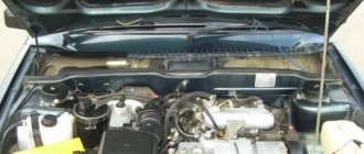
Rework
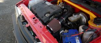
To replace a carburetor with an injector yourself, be sure to arm yourself with the following components:
- Cylinder head from VAZ 2112 with receiver and manifolds;
- Knock sensor;
- Throttle pipe with throttle position sensor;
- Mass air flow sensor and a number of other elements.
Replacement kit
When everything is ready, you can get to work.
- Remove the old cylinder head. Plus, remove all attachments in the fuel assembly, gas tank and ignition system.
- Remove the alternator, thermostat, pulleys and belts.
- Install a new gas tank with a pump, borrowed from a donor - an injection VAZ.
- Remove the carburetor and ignition system components that need to be replaced.
- Disconnect the cooling system pipes and hoses. Here, install a completely new kit from the injector.
- Remove the pan.
- Install new pistons from an injection donor and connecting rods at 10. Standard carburetor components are not designed for an injection compression ratio. Plus there are special recesses for other valves.
- Install a new unit with an underflow on the cover for the DPKV, replacing the standard oil pump. If you can remove the cover, then only that will be replaced.
- After removing the old cooling system pipes, install new ones. The best solution is to replace the entire set. Buying it won't really impact your overall budget.
- Prepare everything necessary to mount the 16 valve head. The fasteners match, only the bolts from the old head are long and need to be shortened. Plus, don’t forget to make a size 12 hole in the new head.
- Install new fuel lines from the donor.
- Connect your new gas tank to the lines.
- Route the wiring from the control unit to the fuel pump. You can use old fuel level regulators from a carburetor car.
- Cut a hole in the wall of the engine compartment through which the wiring will be routed. This way you won't have to make the standard wires longer.
- Install the knock sensor by drilling a hole in the block and tapping a size 8 thread.
- Be sure to replace the water pump using a unit from donor 2112.
- Get a new crankcase breather and oil dipstick. Install them instead of the previous ones.
- Install a new cylinder head. Just don't forget to change the gasket, which corresponds to a different head.
- Install a thermostat borrowed from a VAZ 2112.
- Connect the coolant pipes.
- Remove the rear timing cover and rollers. The pulleys from 2112 are dismantled. The belt must be installed in accordance with the marks.
- Install the new generator along with the drive. For the new generator, the upper fasteners will remain intact, since they are not provided for by the design of the carburetor VAZ 2109. Therefore, fasten the pair of lower mounting bolts as securely as possible.
- Place all the sensors in their new places.
- Seal the valve covers with a good quality sealant.
- Assemble the ignition module, wires, spark plugs and other components.
- Install the air filter.
- Get your exhaust system back to normal. The muffler is often left stock, but the resonator and other components are taken from the donor.
- The wiring is connected to the dashboard and the lock.
- Fill in new oil, refuel the car with high-quality fuel.
- Start the engine and take it for a test drive.
Instructions for installing a new panel
If you want to replace a low tidy with a more advanced, high one, then in any case you will have to change the entire center console.
Removal and installation instructions look like this:
- First, you need to turn off the power to the on-board network; to do this, disconnect the battery, remove the steering wheel, as well as the steering column switches and the ignition switch. You will also need to disconnect the ignition relay.
- Next, unscrew the two bolts that secure the control panel visor and remove it.
- Now you need to compress the spring and remove the shield itself from the center console. Disconnect all wires and connectors connected to the dash, including the speedometer cable, the econometer hose, and the odometer cable. After this, the tidy can be moved to the side.
- Then remove the regulator from the hydrocorrector of the optics light, the tidy light switch knob, as well as the interior heater and fan regulators. To do this, pull the controls towards you.
- After this, unscrew the two bolts securing the center panel trim on the sides; the trim itself can be moved towards you. Then you need to disconnect the connectors.
- Now the key in the lock should be turned to position “0”, this will disable the anti-theft system. A connector with wires is connected to the lock itself; it must be disconnected. Next, unscrew the two nuts and two bolts, after which you can remove the steering column pipe with the switch.
- Remove the choke handle located under the instrument panel. Pull it towards you so that you can feel the pull. You need to unscrew the two bolts that secure the damper guide rod, after which the choke can be removed.
- Now you can unscrew four more screws that secure the heater control panel in the car. Unscrew the bolts located on the side of the shield on both sides. Also unscrew the lower console mounting bolts with nuts that secure the control panel lighting switch and the optics hydraulic corrector. To do this you will need a 22mm socket wrench, it must be high.
- After completing these steps, you need to unscrew the bolt that secures the center console in the glove compartment. Then all you have to do is unscrew one bolt at a time on each side securing the center console. The console itself can then be dismantled.
- As for installing a new high panel with tidy, this process does not present any particular difficulties. All dimensions at the mounting points on the body are the same, but this procedure also has its own characteristics. To install your new console, you will need the appropriate wiring harness. If you use an existing harness, then you will need to rearrange the terminals in it, taking into account the connection diagram. In addition, it will be necessary to change the cables leading to the heater to longer ones, the same applies to the speedometer cable. If you are installing a new console, you will also need other roof pillar side trims, these must be installed before you install the console. Since the new dashboard will not use a flow meter, the tube from it will need to be plugged. In addition, the signal to the tachometer will need to be supplied from wire K on the coil, which is connected to the speed sensor cable bracket.
- Immediately before installation, you should reassemble the new console, and wrap the connection points of the blowers with electrical tape and, preferably, glue them with foam rubber or anti-creaking agent. It is also necessary to change the foam rubber of the heater, since the old one will no longer be able to perform its functions. Also make sure that the choke can close completely and remember that the cable from the new speedometer should be installed before you install the console. The assembly procedure begins with laying a new wiring harness and connecting all connectors. Before you finally assemble everything, turn on the dashboard and check how all the indicators and gauges work. After this, the console can be put back in place.
Peculiarities
VAZ 2114 cars have many innovations compared to 2109, in particular, this concerns electrical wiring.
Whether it is an injector or a carburetor, the wiring diagram for the VAZ 2114 is located in:
- vehicle interior;
- in the engine compartment;
- behind the car body.
It should be noted that carburetor VAZ 2114 were produced only from 1997 to 2000, then they were equipped with carburetors from the VAZ 2108.
But new engines have a more powerful ignition system; accordingly, the electrical control circuit is also characterized by certain features, for example:
- There is a new harness for connecting to the ignition module terminal. This component sends signals to the spark plugs through high-voltage wires.
- Another harness was added to allow mounting of the switch.
- Additional wiring has appeared to connect the adsorber valve to the injection system controller.
Wiring and equipment diagram 2114
Many VAZ 2114 car owners mistakenly believe that thanks to the ignition module, they don’t have to use a coil. In fact, this device is equipped with two coils and two switches. One of the coils transmits the signal to the first and fourth cylinders, and the second - to the second and third.
The equipment system of VAZ 2114 cars with an injector engine has undergone certain innovations not only due to the addition of new electrical equipment, but also as a result of modernization of the car as a whole:
- it is possible to install a heated side mirror device;
- you can connect the front seat heating system;
- VAZ 2114 car owners can install PTF, etc.
Engine compartment
So that a VAZ 2114 with an injector engine can operate on a lean combustible mixture, the car is equipped with:
- forced gasoline injection system into each individual cylinder;
- connecting an improved ignition system characterized by higher power;
- added ECM - injection engine control system.
BC display on a car dashboard
As is known, to ignite a lean combustible mixture there must be a more powerful spark transmitted through high-voltage explosive wires. A spark is transmitted through the explosives of the VAZ 2114 injector when the piston is located at top dead center. This control and connection scheme via high-voltage wires was implemented thanks to the installation of the module.
The operating principle of the device is as follows:
- a generator is used to generate alternating electric current;
- the current passes to the control unit, where it is converted into direct current;
- further, the current flows to the windings of the coils in accordance with the control circuit;
- the secondary winding begins to generate high voltage for transmission through high-voltage explosive wires;
- then, through the same high-voltage explosive wires, the voltage passes to the spark plugs.
Salon
As for the interior, the manufacturer replaced the center console in the VAZ 2114, which has certain differences:
- there is no longer a glove compartment in the upper part, it is installed lower;
- the dashboard was replaced;
- an on-board computer appeared in the VAZ 2114.
Diagnostics of resistance with a multimeter
As a result of such changes and the replacement of old elements with new ones in the VAZ 2114 with an injector engine, the control circuit and wiring connections have also changed:
- another harness appeared for connecting the on-board computer;
- a sensor for monitoring the temperature level outside the window has been added, which is mounted in front of the radiator;
- A voltmeter relay has been added.
In addition, another block of wires was added to the control circuit to control the power windows.
Installing a Solex carburetor on the engine of VAZ 2108, 2109, 21099 cars
We install the Solex carburetor on the engine of VAZ 2108, 2109, 21099 cars after removing it for repairs or when installing a new carburetor.
— A key set to “13” for tightening the carburetor mounting nuts. It is most convenient to use a socket wrench or a socket with a wrench.
— Two keys “8” for the screws for fixing the rod of the carburetor air damper drive and its shell
— Phillips screwdriver, for tightening the carburetor cover screws and tightening the fastenings of hose and pipe clamps.
— We clean the intake manifold and the area on it for installing the carburetor from contamination.
— We check the carburetor mounting studs on the engine intake manifold (condition of the threads, reliability of fixation).
— Remove the top part (cover) of the carburetor.
You don’t have to do this, but with the cover removed there is better access to the carburetor mounting nuts.
The procedure for installing a Solex carburetor on the engine of VAZ 2108, 2109, 21099 cars
Install three gaskets under the carburetor
In this order: sealing gasket, thermal insulation spacer, sealing gasket.
Install the carburetor body onto the intake manifold
We put it on the studs with the holes in the flange and lower it all the way down. The carburetor float chamber should face the nose of the car. We screw the carburetor mounting nuts onto the studs and tighten them crosswise, in several passes, with a wrench set to “13”. Tightening torque 3-4 N.m.
Attach the carburetor heating unit
We fix it to the carburetor with a screw. If hoses have been removed from the heating block, install them on the block pipes and secure them with clamps.
Installing the upper part (cover) of the Solex carburetor
When installing, carefully lower the floats into the float chamber, trying not to bend their arms or change their position. We secure the cover with five screws using a Phillips screwdriver. Tighten crosswise.
Connecting the fuel hoses
There are only two of them: a thick hose - the fuel supply line, is put on the thick fuel fitting of the carburetor. Thin - “return” (return line), fits onto the thin fuel fitting of the carburetor. Fastening with clamps, which must be placed loosely on the hoses before installing them on the fittings. We tighten the clamps with a Phillips screwdriver; you can also use a spanner wrench set to “7” or “8”.
Attach the hose of the small branch of the crankcase ventilation
The hose runs from a fitting on the valve cover to a separate fitting on the carburetor body. It is not necessary to secure it with clamps.
We connect the tube from the vacuum ignition timing regulator
The tube goes from the fitting of the vacuum ignition timing regulator housing on the distributor to the fitting on the carburetor body. There is no need to secure the tube with clamps.
Attach the cable drive of the throttle valves
Turn the throttle valve drive sector clockwise. We thread the tip of the drive cable into the hole in the sector and run the cable along the notch on it. We put the return spring with one edge on the sector, the other on the bracket. The cable tension may need to be adjusted. See “Adjusting the throttle valve drive of the first chamber of the Solex carburetor.”
Installation instructions for on-board computer
In this article we will look at the process of installing the Prestige on-board computer with diagnostic and error reading functions.
For work we will need:
- Screwdrivers,
- on-board computer,
- wire 1m long.
We remove the plug on the central dashboard and look for a 9-pin wiring block in it. This block must be present on all cars of our model. All that remains is to connect the block to the computer and that’s it, but we need to draw a K-line.
How to draw a K-line?
- We take our wire and install it in the second contact of our block.
- We throw the opposite end of the wire under the instrument panel down to the diagnostic block (for convenience, you can unscrew the right side panel).
- Having stretched the wire to the diagnostic block, we connect it to the “M” socket if you have a EURO-2 block or to the 7th socket if you have a EURO-3 block (it is very common that the diagnostic block for Euro-3 is installed upwards on the car feet, keep this in mind)
- Now we connect the on-board computer, insert it into its normal place and check it.
For a more complete and clear idea of the work, a diagram is presented.
What to do if there is no socket for the on-board computer under the instrument panel?
In this case, all that remains is to assemble a new block: buy a 9-pin block and run wires to it according to the following diagram:
- fuel consumption signal (green wire)
- ignition (orange wire)
- + 12 volts (red/white wire) red wire with white stripe
- mass (black)
- speed sensor (brown wire)
- 6k line (most often gray or black wire)
- mute (green/red wire) green wire with a red stripe
- backlight (white wire, or can be taken from the size button)
- fuel level sensor (pink)
How to remove the high type panel
If your VAZ-2109 has a high panel model installed, then you need to act differently:
- First remove the steering wheel to gain access to the instrument panel.
- If you have a carburetor engine, pull out the choke and remove the handle from it.
- Now you need to remove the decorative trim; it is held on by two screws.
- Remove the ashtray and cigarette lighter.
- Pull the fan control handle towards you.
- Use a screwdriver to pry off the decorative control knobs for the interior heater drive.
- Be careful when removing the power wire connectors that go to the heater switch and to the heating control light.
- Remove the handles for the headlight hydraulic adjustment and the instrument panel lighting control.
- Use a socket to turn these adjusters and gently push them inward.
- Remove the air deflectors for the left and right side windows, and also remove the fasteners that were located under them.
- Pry the headlight switch with a screwdriver and pull it out to the length of the wires, disconnect it from the power supply. Place the block back behind the plastic part.
- Remove the stereo or standard radio, and then unscrew the center mount of the decor.
- Along the edges of the decorative trim there are latches that will need to be pressed in order to remove the decorative part of the torpedo by moving upwards.
- Disconnect power from the cigarette lighter, backlights, and hazard warning lights.
- Remove the decorative trims and speakers, disconnecting them from the wiring. After this, turn off the power to the heated rear window and fog lamp switches.
- Unscrew the fasteners and remove the instrument panel, remove the central screw on the speedometer and disconnect it from the cables. De-energize the shield.
- Turn off the power and remove the ignition switch, disconnect the choke control rod from the power supply.
- Disconnect the illumination lamp of the compartment for personal belongings from the power supply. Unscrew the remaining fasteners on the left and right and remove the panel.
Installing a europanel on a VAZ 2109 carburetor
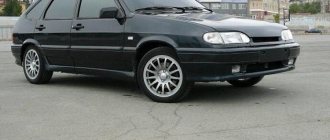
The topic of today's article is quite interesting. This is the installation of a VAZ 2114 panel on a VAZ 2109 (carburetor) and other experiments with the Nine dashboard.
Let's not talk about such things as the justification of these actions. In the end, each car owner decides for himself what his car will look like. But still, we can say with confidence that the instrument panel of the VAZ 2114 looks much better than the original panel and dashboard from the VAZ 2109.
Let’s say right away that installing a Europanel on a VAZ 2109 (carburetor) is a very troublesome process, and first you need to remove the instrument panel of the VAZ 2114.
First, there is a difference in wiring. And you will have to delve into the instructions and pinouts. Otherwise it may “not fly”.
In terms of price, installing a VAZ 2114 torpedo in a VAZ 2109 (carburetor) can cost five to ten thousand rubles, depending on where you buy it and who will do the installation. A new one in cellophane can cost more.
How difficult this process is if you do it yourself depends on how well you understand auto electrics. And in electrics, as such. You may have to actually redo some wiring. It rarely happens that everything starts up and starts from scratch, especially when we are talking about tuning a VAZ 2114 or any other basin. Also, during this kind of repair, it is necessary to look at the diagram of the VAZ 2114 instrument panel in order to accidentally prevent another mistake.
Most likely, you will have to redo the wiring and change the mounting block. Some experts recommend installing wiring from a VAZ 2115.
Installing a VAZ 2114 instrument panel on a VAZ 2109 (carburetor) makes the interior of your car more modern, “newer”. You can also replace the steering column to maintain a sense of integrity of the picture.
The beautiful and more modern dashboard of the VAZ 2114 requires its costs. So you will have to spend a lot of time and effort to put it in order, replace the wiring and connect everything correctly.
The topic of today's article is quite interesting. This is the installation of a VAZ 2114 panel on a VAZ 2109 (carburetor) and other experiments with the Nine dashboard.
Let's not talk about such things as the justification of these actions. In the end, each car owner decides for himself what his car will look like. But still, we can say with confidence that it looks much better than the original panel and torpedo from the VAZ 2109.
Let's say right away - installing a Europanel on a VAZ 2109 (carburetor) is a very troublesome process, and first you need to.
First, there is a difference in wiring. And you will have to delve into the instructions and pinouts. Otherwise it may “not fly”.
In terms of price, installing a VAZ 2114 torpedo in a VAZ 2109 (carburetor) can cost five to ten thousand rubles, depending on where you buy it and who will do the installation. A new one in cellophane can cost more.
How difficult this process is if you do it yourself depends on how well you understand auto electrics. And in electrics, as such. You may have to actually redo some wiring. It rarely happens that everything starts up and starts from scratch, especially when it comes to any other basin. Also, during this kind of repair, you need to look into it so as not to accidentally make a mistake again.
Most likely, you will have to redo the wiring and change the mounting block. Some experts recommend installing wiring from.
Installing a VAZ 2114 instrument panel on a VAZ 2109 (carburetor) makes the interior of your car more modern, “newer”. You can also replace the steering column to maintain a sense of integrity of the picture.
Beautiful and more modern requires its costs. So you will have to spend a lot of time and effort to put it in order, replace the wiring and connect everything correctly.
Tuning a VAZ 2108 (tuning eight) with your own hands is easier than ever
Carburetor Colex 21083 and its design
New cars up to 500,000 rubles in good configuration
And so, I’ll say right away that I didn’t take a lot of photos, because.. =( (Thanks to Serega (Sega535) for telling me about this site!)
Communities › VAZ: Repair and Modification › Blog › Instrument panel from 2114 to 2109 carb
Good day.
I present to you my version of fitting a European torpedo into a carburetor nine. The entire process of installing a torpedo can be divided into two parts: 1. Mechanical - that is, everything that concerns gluing, assembly, fastening, etc. 2. Electrical - in other words, connecting all the electrical components of the panel.
So, we have a VAZ 21093 with a carburetor and a low panel. Based on an ad, I found a used panel 2114 almost complete. The kit included: 1. Torpedo (2 glove compartments)
;
2. Panel shield; 3. Panel shield plug; 4. Box for small items + ashtray; 5. Instrument panel (2 windows)
;
6. BSK (squeaker)
;
7. Console screens (left and right)
;
8. Mounting crossbars (4 pieces)
;
9. Floor tunnel cover; 10. Rear ashtray; 11. Air ducts (3 pieces in the panel + interior)
;
12. Small things (twists, buttons, light guides, screws, staples, etc.)
;
I paid 7 thousand rubles for such a set. Additionally I bought: 1. Steering column 2114 - 3 thousand rubles; 2. Steering column cover 2114 - 300 rubles; 3. Front seat belts 2114 - 500 rubles, used; 4. Torpedo wiring - 1 thousand rubles (for a carb tag)
;
5. Mounting block 2115 - 2.5 thousand rubles; 6. Ignition switch 2110 - 500 rubles; 7. Small things (relays, wires, terminals, contacts, etc.)
- about 200 rubles.
The total purchase estimate is 15 thousand rubles
. If you take not a used one, but a new instrument panel 2114, then add about 5 thousand more rubles.
So, let's start the assembly from point 1. First, we thoroughly wash everything. We start by gluing the air ducts both inside the panel and in the cabin. After all, it’s no secret that they are joined and fastened in such a miraculous way that it blows and siphons where it is not needed at all. I used foam rubber and Moment adhesive tape. I glued the foam rubber with a slight tolerance over the edges of the parts for better compaction, and then rewound everything on top with tape in several layers.
In addition, I taped the junction of the panel and heater air ducts at the top and the junction of the heater with the cabin air duct at the bottom, all using the same technology:
Then I pasted over the plastic of the panel in the places where its parts came into contact - the dashboard, the beard, the glove compartment, all the trims and ends of the panel (they creaked on the door trims)
:
Finished with sizing. Let's move on to the panel fastenings. To secure the 2114 torpedo to the 2109 body, two studs are missing at the beginning of the floor tunnel and two more studs at its end (for fastening the floor tunnel lining)
. Using trial and error, I made some adapters for existing mounts:
In the case of the fasteners for the floor tunnel lining, I had to tinker with it - it did not fall into place due to the fasteners for the front seat belts. As a result, I cut off the excess, and took the brackets themselves along with a set of belts from 2114 and screwed them to the SBC seats. You can read about the assembly of the latter HERE. Very high-quality conversion of stock seats - cheap and cheerful. Let's return to the floor covering. The transformations looked like this:
Finally, about the mounting “ears” to the steering column. They are fastened with 2 bolts and 2 studs - but they all turned out to be short. I replaced the bolts with longer ones, but I didn’t change the studs, what if I stripped the threads? As a way out of the situation, I cut off the grooves from the “ears”. Progress:
Now let's talk about innovations. Firstly, I installed electric windows in the front doors, but I filed the buttons into the beard, next to the ashtray. There are only two buttons - both people sitting in front can reach it, there is no need to run wires in the door and hang additional ones. button for the driver.
Secondly, I installed the visor lock, and put the button in place of the backlight level control. The latter, in turn, replaced the hydraulic corrector control, and eliminated the corrector itself in principle, because The supplied headlights do not provide for it at all.
And thirdly, I put the choke handle in place of the standard immobilizer. Comfortable and beautiful, my opinion.
We are done with manual assembly. Let's move on to point 2 - fiddling with the electrics. In essence - nothing complicated. When I first started this work, my knowledge of electrical engineering was near zero. But nothing, practice helped the young talent learn what stripping, soldering, heat shrinking, contact, chain, ringing are... and many other scary words