FakeHeader
Comments 9
Not right. Contact C goes to connection point S12, and this is ground. If the wiring is intact, but error p1135 does not go away, then the heater itself in the oxygen sensor is faulty. And you need to measure AD - approximately 0.45 V and BC battery power.
A D = 2.82 BC = 12.12 Battery = 12.24
Not right. Contact C goes to connection point S12, and this is ground. If the wiring is intact, but error p1135 does not go away, then the heater itself in the oxygen sensor is faulty. And you need to measure AD - approximately 0.45 V and BC battery power.
As I understand it, A-18 ECU contact B- 63.44 ECU contact C- ground? (Put it directly on the body?) D- 48 ECU contact
A- 18 contact of the ECU, D- 48 contact of the ECU, Read the measurements from the diagnostic scanner, because A reference voltage is applied to A, which you measure when you throw the second probe at C (ground). B - connection point S2 which is recorded from the main relay of the ECU +12 volts, C - connection point S12 is connected to the vehicle ground. When you measure AD, you get a voltage drop across the ECU measuring element, which is why the tester shows a lower voltage. If there is 12 volts on the aircraft, but error 1135 does not go away, then the heating element of the sensor itself is faulty. If the sensor itself is working, it should produce a sinusoid on the scanner, but only when it warms up to operating temperature from the exhaust gases.
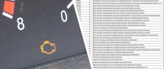
Of course, this is not a happy situation for car owners if the check engine lights up on the car’s dashboard. In this case, you have to contact a specialized service station, where they will diagnose the engine, or if you have an on-board computer installed, identify the breakdown yourself by deciphering the VAZ error codes.
Common Problems Causing Code P0135 on Different Vehicles
In some Acura, Honda, Lexus and Toyota , this code is known to be caused by a faulty sensor heater element. A faulty oxygen sensor (bank 1, sensor 1) can be confirmed by measuring the resistance of the sensor's heating element.
The resistance should be low, usually between 0.9 and 10 ohms, depending on the vehicle. Specifications for different vehicles can be found in the owner's manual. Replacing the sensor often solves the problem.
On some Chrysler , the P0135 code may be caused by an improperly replaced sensor. Different types of sensors may be used on the same vehicle, depending on the vehicle's production date. It is important to check the correct sensor part number using the vehicle's VIN number.
Corrosion on the DC connector is known to cause this code to appear in many vehicles. The connector should be inspected for corrosion. If present, you need to clean the terminals or replace the connector. For example, the Chrysler service bulletin for Dodge Ram recommends repairing the sensor wiring harness using a special repair kit.
In some older Mazda , corrosion of the wiring inside the fuse box can cause code P0135. This can be confirmed by checking the 12V voltage and ground at the sensor.
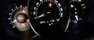
Error codes on the dashboard of Priora 2170, Kalina 1119:
- - turn off the ignition
- — press and hold the “Reset” button plus turn on the ignition, LCD control will start
- — press any LCD button and the program version will appear
- — press any of the control buttons again, error codes should be displayed on the positions of the first and second lines of the LCD
- — press and hold the “Reset” button for more than 3 seconds. to reset error codes
- — press any of the control buttons to control the LCD
Error codes:
- 2 - increased voltage of the on-board network
- 3 - fuel level sensor error
- 4 - coolant temperature sensor error
- 5 - outside temperature sensor error
- 6 - engine overheating
- 7 - emergency oil pressure
- 8 - brake system defect
- 9 - battery is discharged
- E - error detection in the data packet stored in the EEPROM.
Description of error P0480
The cooling fan is electrically controlled by the engine control unit via a relay based on sensor readings:
- — Engine Coolant Temperature (ECT) Sensor
- — Incoming air temperature (IAT) sensor
- — Air conditioning selector switch
- — Air conditioning refrigerant pressure sensor A/C
- — Vehicle Speed Sensor (VSS)
The ECM controls the fan by completing a control circuit that turns on the fan relay. The cooling fan relay turns on when the following conditions are met:
- Engine coolant temperature reaches 106°C (223°F) or more.
- The air conditioner clutch engages.
- The vehicle speed is less than 60 km/h.
The cooling fan relay turns on regardless of vehicle speed when the following conditions are met:
- -Engine coolant temperature has reached 151°C (304°F) or more.
- High refrigerant pressure in the air conditioning system.
Decoding error codes of the VAZ electronic control unit
- P0030-Oxygen sensor heater before the converter, control circuit open
- P0031-Oxygen sensor heater before the converter, control circuit short to ground
- P0032-Oxygen sensor heater before the converter, control circuit shorted to board. net
- P0036-Oxygen sensor heater after the converter, control circuit open
- P0037-Oxygen sensor heater after the converter, control circuit short to ground
- P0038-Oxygen sensor heater after the converter, control circuit shorted to board. net
- P0102-Mass Air Flow Sensor Circuit Low Signal
- P0103-Mass air flow sensor circuit, high signal level
- P0112-Air temperature sensor circuit low signal
- P0113-Air temperature sensor circuit, high signal level
- P0116-Coolant temperature sensor circuit, signal out of acceptable range
- P0117-Coolant temperature sensor circuit low signal
- P0118-Coolant temperature sensor circuit, high signal level
- P0122 - Throttle Position Sensor Circuit Low Signal
- P0123 - Throttle Position Sensor Circuit High Signal
- P0130-Oxygen sensor before the converter is faulty
- P0131-Oxygen sensor circuit to converter, low output level
- P0132-Oxygen sensor circuit to converter, high output level
- P0133-Oxygen sensor circuit to the converter, slow response to changes in mixture composition
- P0134 - The oxygen sensor circuit to the converter is inactive
- P0136-Oxygen sensor after the converter is faulty
- P0137 - Oxygen sensor circuit after the converter, low signal level
- P0138-Oxygen sensor circuit after the converter, high signal level
- P0140 - The oxygen sensor circuit after the converter is inactive
- P0141-Oxygen sensor after the converter, heater is faulty
- P0171 - Fuel supply system too lean
- P0172 - Fuel system too rich
- P0201-Injector cylinder 1, control circuit open
- P0202-Injector cylinder 2, control circuit open
- P0203-Injector cylinder 3, control circuit open
- P0204-Injector cylinder 4, control circuit open
- P0217-Engine temperature is higher than permissible
- P0230-Fuel pump relay circuit malfunction
- P0261-Injector cylinder 1, control circuit short to ground
- P0263-Injector driver fault 1
- P0264-Injector cylinder 2, control circuit short to ground
- P0266-Injector driver fault 2
- P0267-Injector cylinder 3, control circuit short to ground
- P0269-Injector 3 driver malfunction
- P0270-Injector cylinder 4, control circuit short to ground
- P0262-Injector cylinder 1, control circuit short to on-board network
- P0265-Injector cylinder 2, control circuit shorted to on-board network
- P0268-Injector cylinder 3, control circuit short to on-board network
- P0271-Injector cylinder 4, control circuit short to on-board network
- P0272-Injector 4 driver malfunction
- P0300 - Random/multiple misfires detected
- P0301-Cylinder 1, misfire detected
- P0302-Cylinder 2, misfire detected
- P0303-Cylinder 3, misfire detected
- P0304-Cylinder 4, misfire detected
- P0326-Knock sensor circuit, signal output out of acceptable range
- P0327 - Knock sensor circuit low signal
- P0328 - Knock sensor circuit, high signal level
- P0335 - Crankshaft position sensor circuit is faulty
- P0336-Crankshaft position sensor circuit, signal out of acceptable range
- P0337 - Crankshaft position sensor, short to ground
- P0338-Crankshaft position sensor, open circuit
- P0340 - Camshaft Position Sensor Malfunction
- P0342-Phase sensor circuit, low signal level
- P0343-Phase sensor circuit, high signal level
- P0346-Phase sensor circuit, signal out of acceptable range
- P0351-Ignition coil of cylinder 1 (1-4), control circuit open
- P0352-Ignition coil of cylinder 2 (2-3), control circuit open
- P0353-Ignition coil of cylinder 3, control circuit open
- P0354-Ignition coil of cylinder 4, control circuit open
- P0363-Misfire detected, fuel supply to idle cylinders is turned off
- P0422 - Neutralizer efficiency below threshold
- P0441-Gasoline vapor recovery system, incorrect air flow through the canister purge valve
- P0444-Canister purge valve, control circuit open
- P0445-Canister purge valve, control circuit short to ground or on-board network
- P0480-Fan relay, control circuit open
- P0481-Cooling fan 2 circuit malfunction
- P0500-Vehicle speed sensor is faulty
- P0506-Idle system, low engine speed
- P0507-Idle system, high engine speed
- P0511-Idle speed control, control circuit faulty
- P0560-On-board network voltage is below the system operability threshold
- P0562-On-board voltage, low level
- P0563-On-board voltage, high level
- P0601-Engine management system controller, ROM checksum error
- P0615-Additional starter relay, control circuit open
- P0616-Additional starter relay, control circuit short to ground
- P0617-Additional starter relay, control circuit shorted to on-board network
- P0627-Fuel pump relay, control circuit open
- P0628-Fuel pump relay, control circuit short to ground
- P0629-Fuel pump relay, control circuit shorted to on-board network
- P0645-A/C compressor clutch relay, control circuit open
- P0646-A/C compressor clutch relay, control circuit short to ground
- P0647-A/C compressor clutch relay, control circuit shorted to board. net
- P0650-Malfunction indicator lamp, control circuit faulty
- P0654-Instrument cluster tachometer, control circuit faulty
- P0685-Main relay, control circuit open
- P0686-Main relay, control circuit short to ground
- P0687-Main relay, control circuit shorted to on-board network
- P0691-Fan relay, control circuit short to ground
- P0692-Fan relay, control circuit shorted to on-board network
- P1102 - Oxygen Sensor Heater Resistance Low
- P1115 - Oxygen sensor heating circuit faulty
- P1123 - Rich mixture at idle
- P1124 - Lean mixture in idle mode
- P1127 - Rich mixture at Partial Load
- P1128-Lean mixture in Partial Load mode
- P1135 - Oxygen sensor heater circuit 1 open, short circuit
- P1136 - Rich mixture in Light Load mode
- P1137 - Lean mixture in Light Load mode
- P1140 - Measured load differs from calculation
- P1141 - Oxygen sensor 1 heater malfunction after converter
- P1171-Low level CO potentiometer
- P1172-High level CO potentiometer
- P1301-Cylinder 1, misfire detected, critical for the converter
Troubleshooting
Note! If you are unsure of your own abilities, the motorist is strongly recommended to seek help from a specialized workshop or a qualified technician.
If you have the necessary equipment, you can determine whether 8 or 16 valves are broken in a Lada Priora car yourself. Due to the simple design of the machine, repairs do not require the user to have in-depth knowledge of mechanics, electronics or other sciences.
Hello. I got error 1570 on BC - “immobilizer, no positive response or open circuit.” It appears when you turn the ignition key in the form of a beeping buzzer (the car with the key on the dashboard does not blink or light up), and it does not stop for some time after starting the engine. Resetting the error does not help. How to defeat her?
How to diagnose a VAZ-2114
How to use the self-diagnosis function without taking into account the on-board computer?
- Press the car daily mileage reset button.
- At the same time, turn on the ignition with the key in the first position.
- Remove your finger from the key responsible for operating the odometer - the arrows should start moving.
- Press the key again and release - this simple method will fix the firmware version.
- All that remains is to press the button a third time, then release it; If there is a malfunction, an error code will appear on the screen.
Example of step-by-step diagnosis of code P0135
The check engine light came on on a Honda. Trouble code P0135.
Clearing the fault code using the OBD2 diagnostic scanner. According to this vehicle's owner's manual, the first step is to clear the code and check to see if it returns. This is necessary to see if the code is intermittent or constant.
We erased the code and started the car. The Check Engine immediately returns with the same code.
The next step, according to the instructions for this Honda, is to turn the ignition to the LOCK position and check fuse No. 14 FI SUB (15 A). The fuse location is indicated on the back of the fuse box cover.
Check to see if the fuse is blown. We checked the FI SUB fuse - everything is fine. The next step according to the manual is to test the PGM FI slave relay. We tested the relay - it also worked.
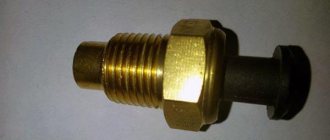
The next step in the diagnostic process is to disconnect the oxygen sensor connector and measure the resistance of its heating element.
The multimeter shows 235 kOhm (kiloohm). According to the repair manual, the resistance should be between 2.5 and 4 ohms. This means that the DC heating element has failed and the sensor must be replaced.
We purchased a new front oxygen sensor and tested the resistance of the heating element for comparison.
As you can see, its resistance is 3.4 ohms. We installed a new sensor and cleared the code. The check engine has not returned, this car is fixed.
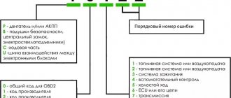
How to decipher error codes
If you have ever seen how a VAZ-2114 is diagnosed using special equipment in a service station, you probably noticed that the error code has 4 digits. In our case, during self-diagnosis, the code includes only 2 numeric characters. In general, the codes mean the following:
- if the number 1 appears, it means the microprocessor is malfunctioning;
- 2 – the operation of the sensor circuit indicating the fuel level in the tank leaves much to be desired;
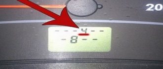
- 4 – there is too high voltage in the electrical circuit;
- 8 – the voltage, on the contrary, is too low, it is not enough for the VAZ-2114 to operate properly;
- 13 – there is no signal from the indicator of available oxygen;
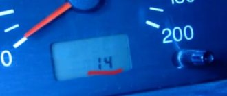
- 14 – high signal value of the coolant temperature indicator, filled in for efficient operation of the car’s cooling system;
- 15 – this signal, on the contrary, is too low;
- 16 – voltage units in the on-board network are off scale;
- 17 – low voltage values of the on-board network;
- 19 – the signal from the locking component regarding the position of the crankshaft is received incorrectly or untimely;
- 24 – the sensor that records the vehicle speed is faulty;
- 41 – the phase sensor signal is received incorrectly;
- 51 – there are problems in the functioning of the operational product responsible for memorization;
- 53 – it’s time to repair the CO potentiometer;
- 61 – lambda probe does not work.
Why does runtime error 1135 occur?
“Nero Error 1135” can most often occur when loading Nero. We can determine that errors during the execution of error 1135 come from:
Error 1135 Crash - The error number will cause the computer system to lock up, preventing you from using the program. This occurs when Nero does not respond to input properly or does not know what output is required in return.
Memory Leak “Nero Error 1135” – When Nero memory leaks, it can cause your device to run slowly due to lack of system resources. There are some potential issues that could be causing problems at runtime, with incorrect coding leading to infinite loops.
Error 1135 Logic Error - Nero's logic error occurs when it produces incorrect output despite the user providing correct input. It materializes when Nero's source code is faulty due to a faulty design.
Such Nero Error 1135 problems are usually caused by corruption of a Nero-related file, or in some cases, its accidental or intentional deletion. Typically, any problem with a Nero file can be resolved by replacing the file with a new copy. If Nero Error 1135 occurred as a result of uninstalling it due to a malware infection, we recommend running a registry scan to clean up any invalid file path references created by the malware.
How to decipher the codes of VAZ-2114 on-board computers
What codes can you look for when diagnosing the Lada 2114 in relation to on-board computers? These devices are exactly the same electronics as those on foreign cars, but the problem is that VAZ-2114 they are capable of malfunctioning, but this does not mean at all that you should avoid diagnosing the car yourself using this product.
So that you do not have to study the full list of errors and their explanations, experts have selected only the most common ones:
- 0102, 0103 – the indicator responsible for regulating the mass flow of air flow gives an insufficient level signal;
- 0112, 0113 – the signal from the sensor recording the temperature regime of the incoming air is faulty;
- 0115-0118 – the condition of the VAZ-2114 coolant temperature meter leaves much to be desired; to eliminate the breakdown, a complete replacement of the indicator is necessary;
- 0122, 0123 – interference or an incorrect signal is coming from the indicator that controls the throttle position; the component requires immediate replacement;
- 0130, 0131 – the device indicating the oxygen level is faulty;
- 0135-0138 – the equipment heating the oxygen meter does not work, so it is worth replacing the element;
- 0030 – there are malfunctions in the functioning or a break in the entire chain of control and regulation of the oxygen meter heater up to the neutralizing mechanism;
- 0201-0204 – a break in the injector control chain has been detected;
- 0300 – there are misfires in the on-board computer, this is obvious – the VAZ-2114 is difficult to start right away;
- 0301-0304 – misfires were detected in engine devices;
- 0325 – the on-board computer detected an open circuit in the detonation mechanism chain;
- 0327, 0328 – malfunction of the detonating sensor; the situation can only be saved by replacing the equipment;
- 03335, 0336 – malfunction of the crankshaft position sensor;
- 0342, 0343 – the on-board computer indicates a breakdown of the phase sensor;
- 0422 – the neutralizer refuses to work adequately;
- 0443-0445 – the valve that bleeds the adsorber does not work;
- 0480 – the fan cooling the VAZ-2114 is faulty;
- 0500, 0501, 0503, 0504 – the vehicle speed sensor requires repair;
- 0505–0507 – the idle speed controller, which is responsible for the speed, is faulty;
- 0560, 0562, 0563 – the voltage is poorly supplied, which requires more thorough checking and testing; this is the only way to identify areas of the chain that need to be replaced;
- 0607 – detonation channel does not work;
- 1115 – the heating circuit of the oxygen level meter is not functioning properly;
- 1135 – a break in the heating circuit of the oxygen sensor has been detected, there is a high probability that a short circuit has occurred;
- 1171, 1172 – the level of the gas component of the potentiometer leaves much to be desired;
- 1500 – the control circuit of the fuel pump device is broken;
- 1509 – an overload of the idle speed component has occurred;
- 1513, 1514 – the computer has detected an open circuit in the idle mechanism chain;
- 1541 – the regulation and control circuit of the relay suitable for the fuel pump is broken;
- 1570 – the integrity of the traction control system is broken;
- 1600 – there is no connection with the system responsible for the car’s traction control;
- 1602 - occurs very often during diagnostics, means insufficient voltage on the on-board network or its complete absence on the electronic control unit;
- 1606, 01616, 1617 – the mechanism for fixing uneven road surfaces is broken;
- 1612 – faulty reset of the electronic part of the control;
- 1620 – it’s time to change the memory part;
- 1621 – the state of the random access memory sensor is affected;
- 0337, 0338 – the component that controls the position of the crankshaft is not working correctly, a circuit break is possible;
- 0481 – cooling fan does not work;
- 0615, 0617 – the relay circuit is not working adequately, there are breaks and short circuits;
- 1141 – the heating mechanism of the first oxygen sensor, next after the neutralizer of the oxygen level meter, is not functioning correctly;
- 230 – it’s time to change the fuel pump relay;
- 263, 266, 269, 272 – the driver of injectors No. 1-4 does not work, you cannot do without replacing the components;
- 640 – the Check Engine lamp circuit is broken.
What does code P0507 mean?
Trouble code P0507 is triggered when the engine idle speed is higher than expected. All modern engines have a desired idle speed - usually between 600-1000 rpm.
The control unit uses position sensing and throttle adjustment to achieve these speeds. If the idle speed exceeds these set values and the maximum adjustment zone, the control unit will generate this error code.
Code P0507 is a common code for vehicles equipped with Electronic Throttle (E-Gas). Newer vehicles usually use E-gas.
The throttle valve is only called electronic. It replaces the old throttle body with a cable between the gas pedal and the throttle body.
The electronic throttle body uses sensors on the gas pedal and an electric motor in the throttle body to provide the desired acceleration. But this does not mean that this error code must necessarily be related to a faulty throttle valve. It can also have many other causes.
How is self-diagnosis performed?
We have sorted out the main errors on the Priora, now it’s worth finding out how self-diagnosis is performed. The VAZ 2170 with 16 valves has a special controller with which diagnostics are performed. If you have an on-board computer installed, then diagnostics are performed on it. There is also special equipment that allows for a more in-depth check of Priora 16 class systems.
Since most Priora 16 cars already have an on-board computer, we will consider the option without the use of special devices. Diagnostics begins with activation of the test mode. The work proceeds according to the following scheme:
Hello. I got error 1570 on BC - “immobilizer, no positive response or open circuit.” It appears when you turn the ignition key in the form of a beeping buzzer (the car with the key on the dashboard does not blink or light up), and it does not stop for some time after starting the engine. Resetting the error does not help. How to defeat her?