Good night) I can’t sleep, I was sitting making a diagram for connecting additional buttons and closers.
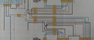
The standard electrical circuit of the ESP (electric windows) of the VAZ 2110 looks like this
I made it into what I needed using PAINTa))
Designations on the diagram: 1) “Black box” (where the relays and fuses are) 2) Ignition switch 3) ESP button of the front right door 4) ESP button of the right rear door 5) ESP gearmotor of the front right door 6) ESP gearmotor rear right door 7) ESP gearmotor of the front left door ESP gearmotor of the driver's door 9) ESP button of the left rear door 10) ESP button of the driver's door 11) Relay for turning on the buttons from the ignition 12) Button for blocking the buttons in the passenger doors 13) Locking relay buttons in passenger doors
Something like this. .I hope experienced electricians will appreciate my work, and if they find a mistake, they will tell me... I don’t pretend that the diagram is 100% correct, I will assemble it according to it, if everything goes well, then naturally the result will be here)
And another question: should the buttons on the tunnel also be run through the blocking relay, i.e. so that only the buttons in the driver's door work or not...
PS in the diagram the buttons in the driver's door and on the tunnel are not blocked.
If it’s not difficult, please rate me in the comments, and if anything is not clear, questions are welcome)))
Selecting window regulators for installation on a VAZ-2110
If you want to install electric windows on your car, you will first need to choose the most reliable device that will serve for many years without causing any problems. On the modern market you can find the following options:
- traditional cable structures, which are relatively easy to install, but differ from others by not having a very long service life, wear out quickly;
- strip devices that are not very convenient to use;
- rack and pinion window lifters, which are deservedly recognized as the most suitable and reliable in operation.
When choosing devices suitable for your car, pay attention to factors such as:
- the speed of raising and lowering the glass, which largely depends on the gear motor installed on the car;
- the ability to use the device in the cold season;
- noise level during product operation.
Taking into account all these factors, you will be able to choose window lifters that will not only work flawlessly, but also will not create any problems in specific operating conditions.
Installing an additional ESP button in the door of a VAZ 2110, 2111, 2112 and operating the ESP without ignition and relay
The content of the article:
ESP operation without ignition and relay for VAZ 2110, 2111, 2112
As we all know, the Internet is full of information on how to wind a wire and make the power windows work without the ignition key, but it seems to me complete nonsense. Let's look into this.
The proposed method on the Internet is this: first of all, we must open our mounting block with fuses and find there the relay responsible for the electric windows.
Having verified it experimentally, namely by turning on the ignition and pulling out the relay, we understand whether the window lifts work or not. If this is what we need, take out the relay.
Then we begin to do some manipulations with the relay by winding wire around it.
I don’t know about you, but I have a question: why do we need this?
We have in our hands an ordinary 4-pin relay, where the principle of operation of the relay is clear to us.
On the Internet they simply suggest that we short-circuit the water contact of the power supply-30 and the output contact of the ESP-87. This will lead to a contact that bypasses the coil (relay), which will only work if it receives power (plus) from the ignition switch (contacts in Relay-85,86-Coil).
So isn’t it easier for us, without making a collective farm, to simply make a jumper to provide power directly?
Make it from a thick wire with a cross-section of 2.5-4 squares so that our jumper does not get hot.
And connect it directly to the block. On the input voltage connector, contact is 30 and output voltage is 87.
Then to turn on the ESP you will not need to turn the ignition key. Since Power (plus) will come to the ESP, bypassing the relay, which will only work when power (plus) is supplied from the ignition switch.
Then there will be no need to farm collectively.
Installation of an additional ESP button in the door of a VAZ 2110, 2111, 2112
I bring to your attention a step-by-step description of the process of installing an additional power window control button (ESP) in the door. The process is not very complicated and time-consuming; everything will take about two hours.
In order to install an additional power window key on the VAZ 2110 door, we will need:
1. 9 meters of wire (I used wires of the following colors: black, yellow, white, 3 meters each) 0.75 mm (section) 2. Button for controlling the ESP (VAZ 2110)* 3. Block for the ESP button 4. Terminals "mother" large - 2 ** 5. Terminals "male" large - 2 ** 6. Terminals "mom" small - 7 ** 7. Terminal "ground" 8mm - 1 8. Blocks for terminals "mother - father" large — 1 (of each type) 9. Plastic clamps (small) — 8 10. Pistons for sprinkling the door trim — 7***
* - in principle, instead of a ten-point rocker button, you can install HIGH-CURRENT (power) buttons from Kalina or Priora, but check with the seller that they are high-current, trigger ones will not work. ** — I didn’t buy these terminals, they came with the pads. *** - they are soft for me, so they didn’t break => I didn’t buy them.
Wiring diagram for the ESP button in the door.
Now we determine the contact numbers on the button and block, according to the diagram:
Okay, we figured it out. The next thing is to find the ESP relay. Typically, the relay is located on top of the mounting block cover. If you have more than one relay installed, then remove them one by one and check if the ESPs are working. The relay, after removing which the ESP stopped working, is the ESP relay.
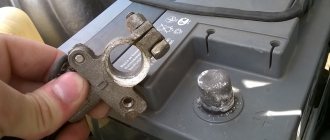
We remove it from the socket and remove the negative terminal from the battery. Then we disconnect the relay itself from the housing. To do this, use a flat-head screwdriver to slightly press the holder latch and press on its body. The relay holder will disengage. The picture shows the latch:
We are interested in the white wire with a black stripe (this is “+ 12 V” after ignition. If you want the ESP to work regardless of the position of the ignition key, then bridge contacts 30 and 87 of the ESP relay - white with a black stripe and blue with a black stripe) :
We connect our “+12 V” wire to it (according to the diagram, it is connected to pin 2 of the block, I used a yellow wire) Now we need “ground”. You can take it from the door, but the contact there is very unstable, so I took the mass from the bolt behind the mounting block. To see this bolt, open the mounting block and look up and slightly to the right).
Crimp the wire that goes to ground at the ground end and attach it to the bolt. (I used black wire for these purposes)
The next step is to connect the plus from the backlight. I ran into the white wire of the ashtray illumination (I also used a purchased white wire for connection), it is located behind the shield on the left, at the feet of the front passenger.
Do not pay attention to the orange wire (+ to the radio backlight).
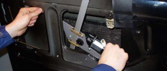
Now, we have connected all three wires that we will run into the door to the sources, then we will need to run them through the corrugation inside the door. Remove the center pillar trim (unscrew one screw in the middle and two at the bottom). Also loosen the fastening of the driver's seat belt on the floor (bolt 17).
To make it easier to route the wires through the corrugation, disconnect it from the door.
Unscrew and remove the door handle (two bolts for a Phillips screwdriver). Then we remove the door trim (card), it is best to do this starting from the bottom. Don't forget to unscrew the nail. We find the blocks (male and female) for the ESP engine and disconnect them.
Now the fun begins. We crimp the three wires we have drawn with little mothers and insert them into the block according to the diagram given above. Accordingly, “+12 V” - (yellow) contact 2
, plus backlight (white wire) -
4
, and ground - black - by
5
.
There are 4 contacts left: 1,3,6,7. We connect the original wire (green with a black stripe) that went to the ESP engine block to 6
, and the orange wire to
3
.
Now the block that will be connected to the ESP engine block: blue wire - 7
, brown -
1
contact.
Here, in fact, is the photo (all numbers and designations are in accordance with the diagram above):
Location of wires in the block:
I tidied this mess up a bit:
We connect the button, connect the ESP relay and the minus to the battery. Let's check... if everything works, put all the parts in the reverse order of disassembly. If the glass works normally with the native ESP buttons, but with the connected ones it goes in the opposite direction, swap 3-6, and 7-1 (was 3 - became 6, was 6 - became 3, etc.) contacts in pads that connect to the original wiring in the door. But first, check that the connection according to the diagram is correct.
How to install and connect power windows on a VAZ-2110
The most preferred devices are rack type, so we will describe the installation process as an example. The connection diagram for the window regulator on a VAZ-2110 car is as follows:
- remove the negative terminal from the car battery to stop the supply of voltage to the on-board power supply network;
- we take the wires that come standard with rack-and-pinion window lifts and make a kind of harness out of them that makes connection easy;
- remove the car mounting block, which will require unscrewing the self-tapping screw that secures the special latch;
- turn the block over and carefully install block Ш1 of the pre-prepared wiring harness into the corresponding connector;
- dismantle the door trim;
- we pull the wires to the electric window drive. To do this, you will need to carefully pass them through the holes in the door itself and the body pillar on the desired side.
After this, buttons or keys are installed that will be used to control the power windows. Depending on your desire, they can be attached either to the door trim of a VAZ-2110 car, or to an existing control panel. In the first case, you will need to use an additional wire, which will allow you to equip the key backlight.
DIY electric windows for a gazelle
We also connect pin “6” of the right key to it. We connect the white wires of the BZ to terminals “3” of the right and left keys and place the block under the console.
We lay the wires from terminals “2” and “5” of the right and left keys into the corresponding doors.
We mark the mounting holes for the ESP strip on the inner panel of each door (see Fig. 3).
We drill two holes with a diameter of 5.2 mm in each door. To prevent the edges of the holes from rusting, we cover them with Movil or paint over them with any enamel.
The right and left window lifters are marked on carriage 3 (see Fig. 3) with the marks “R” and “L”, respectively. We combine the ESP mounting holes with the drilled holes in the inner door panel. If other wires are laid inside the doors (for example, for controlling the electric drive of locks), they should not get under the lower bracket of the rack 2 ESP.
We check that the length of the wires laid to the ESP is sufficient for the extreme positions of its carriage, but not excessive.
We place the wires with the connector inside the door.
We install the window regulator of the other door in the same way.
We connect the battery and turn on the side lights of the car - the ESP control keys should be illuminated. If not, swap the wires on terminals “3” and “6” of the corresponding key.
We turn on the ESP one by one for a short time (remember, there are loose glasses inside the doors) to make sure that they are correctly connected to the power wires. If the direction of movement of the window regulator does not coincide with the position of the key, swap the wires in its connector.
By pressing the corresponding shoulder of the key, lower the carriage down until it stops.
We remove the stop from under the glass, align the grooves on the carriage with the holes in the glass frame.
We check the operation of the window regulator: the glass should move smoothly, without jamming or distortion, and the ESP should turn off in the extreme positions.
Similarly, we assemble the ESP of the second door.
Warnings:
If we use wires not from the power window kit, their cross-section must be at least 0.75 mm2. We carefully insulate all wire connections.
The keys can be placed in another convenient place - the connection principle will not change. We lay the wires without sharp bends, without pulling too much, and if possible we secure them – for example, with electrical tape – to the standard wiring.
Recommendation:
If your vehicle is equipped with a security alarm, it is useful to equip it with an additional power window control module. It automatically raises the windows when the car is armed. The company also plans to equip window regulators with protection units with this function.
Installation process of electric windows
In addition, it is necessary to install the power windows themselves. The procedure is performed in the following sequence:
- temporarily remove the glass seal located on the inside of the door;
- remove the glass, and then dismantle the window regulator fastening mechanism;
- we install devices that will operate from an electric drive;
- connect the negative terminal to the battery and check the operation of the new window regulator;
- We install the glass in place and trim the door.
Our instructions in pictures will help you understand the installation procedure in more detail.
Installation and connection diagram for VAZ 2109 window regulators: step-by-step instructions with photos
- Before starting work, you must turn off the power supply to the vehicle's on-board network from the battery. Or we separately turn off the power circuits for the cigarette lighter and the backlight of the instrument panel and buttons. because The power supply wiring for the power windows will be connected to these circuits in the future.
- Remove the door trim. It can be removed quite easily, but it is better to stock up on mounting pins.
- First of all, we dismantle the mechanism of the standard manual window lifter, fixing the glass (for example, using office tape) in a position that provides access to the place where it is attached to the lifting mechanism.
- Unscrew the bolts securing the door glass to the standard window lifter mechanism.
- We dismantle the guide of the standard window lifter mechanism (trapezium). Unscrew the bottom nut:
- Two nuts in the middle:
- Top nut:
- The guide is free, now all that remains is to unscrew the three nuts securing our window lifter in the area of the rotation handle.
- We take out the entire door window lifter mechanism. To do this, we bring the lower pin of the guide into the hole in the door (see photo).
- By pressing with a screwdriver, we remove the upper fastening of the guide.
- Done, the window lift mechanism is disconnected. We take it out of the door cavity.
- That's it, the standard mechanism has been dismantled, let's start installing a new one. The new mechanism is attached using standard fasteners; you don’t have to drill anything new. We place the window lifter mechanism into the inner cavity of the door through the largest technological hole in an “assembled” form (otherwise it won’t fit), as if in the “open” position of the glass.
- We fasten the mechanism inside the door using two studs, which we insert into two holes that previously held the middle part of the guide of the standard VAZ 2109 window lifter. We combine them and screw on the nuts.
- The next task is to combine the mounts on the window lift linkage system with the mount on the glass. This can be done by supplying power to the power window motor contacts from an external power source, for example, any working car battery.
- When the lift mechanism is combined with the strip on the glass, we connect them using the bolts from the kit.
- It is advisable to lubricate the rubbing parts thoroughly.
- The mechanical part is complete, let's move on to the electrical part.
- We estimate the route for wiring from the door from the electric motor of the window lift drive to the installation location of the buttons - activators. The standard place for buttons in the high panel of the VAZ 2109 is two plugs to the right of the cigarette lighter, and we install them there. The hardest part is running the wiring from the door into the rack and then out of the rack under the dash. For this purpose, there are technological holes in the rack. You may need to use a special probe. The wiring is done with a wire with a cross-section of at least 1 mm. sq. We lay the wires in such a way that they do not touch any moving parts of the door or the ESP mechanism itself. We will take power for the electric windows from the cigarette lighter. We make electrical connections according to the following diagram: When the circuit is assembled, it is necessary to connect the battery power and check the correct operation of our system. We turn on the side lights and check the correct operation of the backlight of the ESP activator keys. If the backlight does not work, swap the sockets on the contacts of the keys, indicated in the diagram as 3 and 6. You can install the power windows in the standard way, here are two diagrams: Connection diagram for power windows on a VAZ 2109 with mounting block 17.3722 (before 1998)
Connection diagram for electric windows on a VAZ 2109 with mounting block 2114-3722010-60, 2114-3722010-10 and 2114-3722010-18 (new model)
This is interesting: Carburetor cleaner
You can read more about the types of mounting blocks for front-wheel drive VAZs here.
- We check the functionality of the window regulators. The glass should move smoothly, without jamming or jerking, and should not come out of the guides. To facilitate the movement of glass in the seal, it can be treated with silicone grease.
- All that remains is to reinstall the door trim.
- That's it, the installation of the window lifters is complete, let's enjoy the completed modification!
How to install and connect electric window lifts “Granat”: video experience
Installing central locking
Installing power steering, part 2: Rack
Installing an electronic tachometer
A more competent solution would be to take power from the mounting block. Added diagrams.
I wanted to see a more experienced solution for supplying power to the beet lifters; the mounting block has a relay on them.
The smartest thing, in my opinion, would be to take power for the ESP from the battery! Practice shows that as long as the current passes through the terminals of the mounting block and its fuses, it is lost! And if you take the main plus from the battery, then the ESP flies like crazy
Some features of power windows on the VAZ 2110
Not much time has passed since they began installing electric windows on the VAZ 2110. However, during this short period, many cases of ESP breakdowns and developments in repairing them have already accumulated.
You can, of course, replace the used device with a new one. But you can go another way, especially since the design of the window regulator allows you to restore its functionality independently. By the way, this can be done without much difficulty. The main thing is that the installation/dismantling and repair instructions are strictly followed. But before you get started, it is recommended to understand the types of these devices.
Installation of an additional ESP button for VAZ 2110
It is important to know!
Every motorist should have a universal device for removing scratches on a car of any color. The effect is visible within 10 minutes, and the action of RENUMAX will pleasantly surprise you with its simplicity and effectiveness. Read more >>>
Standard ESP connection diagram
Changed to this scheme (here without rear ESP)
Connection diagram for additional ESP button.
How the additional ESP button is made on Kalina
To install one duplicate button in the door you will need:
- 2x contact (plastic connector) block male + female 1 pair
- Large male terminals 2 pcs.
- Mom large 2 pcs.
- Mom little 7pcs
- Earth 1pc.
- Power window button 1 pc.
- Button installation cup 1 pc.
- Power window button connector 1 pc.
- Wire diameter 0.75 4 met.
- Door pistons 7pcs
If your ESP buttons have been moved to the doors, then the insert into the harness for additional. the button will look like this
to Kachan for the detailed instructions
The idea is that we need to run 3 wires :
- Ground (Ground, in theory, can be taken into the doors, but there is not always good contact there, so it is better to run a separate ground wire)
- +12V “after ignition” (with power window relay at ChYa)
- illumination (take it from the cigarette lighter, since it is in the middle between the doors.)
Disconnect the negative terminal from the battery.
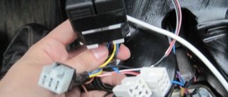
We look for +12V on the ESP relay (black and white wire) to it and screw both of our red +12V
Then we climb through the door. There are 2 wires going to the ESP motor - gray and blue, through a connector. Unplug the connector:
We take 2 wires (I have black and black and white), of such length that we can reach from the original chip with the blue and gray wire going into the corrugated door to our future button. We crimp 2 large male terminals onto them and insert them into the connector. We put it on the chip with blue and gray going into the corrugated door, so that the black comes from the gray, and the black and white comes from the blue:
Insert the wires into the button connector:
- Red +12V
- Black mass
- White backlight
- Black with gray wire chips
- Black and white with blue wire chips
We crimp with small “mothers” and insert the ESP buttons into the connector.
We do it according to the scheme:
- Red +12V to slot 2
- Black ground - in slot 5
- White backlight - in slot 4
- The black wire from the gray wire of the chip goes into slot 6
- Black and white from the blue wire chips - into slot 3 (THREE).
Do not mix up the button connector sockets! That's not all, we need two more short wires, through which we will now connect our button to the ESP motor, like we'll do it as before. For beauty, we take the same colors of wires that were attached to the original chip going into the corrugated door, i.e. black and black and white. It will be like a continuation of the original wires, and in the middle of them is our button. We insert the black wire into socket 1 of the button connector. Black and white - into socket 7.
We crimp the other ends of these wires with large “mothers” and put the purchased connector on them so that when you put this connector on the dangling chip going to the ESP motor:
- The black wire went to the gray ESP motor chips
- Black and white - to the blue wire of the ESP motor chip.
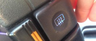
In principle, that's all. Don't pay attention to the orange wire in the photo - it's a mass for heating the mirrors.
The final version.
You can use the button from Kalina, it is more beautiful and a little more expensive than the one from the VAZ 2110.
In order to get rid of constant fines from cameras, many of our readers successfully use Special Nano Film for license plates. A legal and 100% reliable way to protect yourself from fines. Having familiarized ourselves and carefully studied this method, we decided to offer it to you.
In order to get rid of constant fines from cameras, many of our readers successfully use Special Nano Film for license plates. A legal and 100% reliable way to protect yourself from fines. Having familiarized ourselves and carefully studied this method, we decided to offer it to you.
Types of window regulators and the main causes of their breakdowns
Today the following types of window lifters are in use on VAZ:
- rack type (experts consider them the most reliable of all known designs);
- cable;
- plank.
Depending on which company produced the product in question, it can be installed in the car door as standard, or, if it does not fit in size or other technical characteristics, it can be altered without unnecessary problems.
Since both domestic and imported gear motors can be installed on the lift, the described devices, depending on the type and origin of the electric motor, may differ:
- by the speed at which the glass is raised or lowered;
- according to the noise level recorded during operation of the window lifter;
- if possible, its normal operation in winter conditions.
The parts in question can fail for a number of reasons, which can be summarized into two main groups: mechanical and electrical failures. The list of possible reasons looks like this.
- The whole design doesn't work. The cable has broken or become jammed. Lifting mechanism malfunction.
- The electric motor failed due to moisture getting into it. Such a malfunction occurs quite often, since the gearmotor has a leaky housing into which water leaks, which is why rust forms inside the device over time. As a result, spreading corrosion destroys the entire mechanism.
- The power window relay has failed. The performance of this component can be determined by replacing the problematic relay for testing with a guaranteed working one.
- The corresponding fuse has blown. If after installing a new element the device starts to work, then this is the reason. If the new fuse blows again, you need to look for the short circuit.
- Short circuit in the circuit. Its location is determined by which fuse burns when turned on. The cause of this malfunction can be either burnt out wire insulation or a failed gear motor or mechanism switch.
- Breakage of the switch. Determined after replacing the problematic one with a new, known-good switch.
- Break in the common circuit. This can happen due to a mechanical break in the electrical wire, disconnection of the block or poor contact in it.
Return to contents
Power rack-and-pinion windows
Connection diagram and pinout of VAZ power window button
Rack and pinion window lifters are considered one of the most “long-lasting” compared to others. Rack-type ESPs operate on the principle of transmitting rotational motion from an electric motor to gears, with its subsequent transformation into linear movement of racks that perform lifting. In addition to reliability, window lifts of this type lift windows much faster and quieter than cable counterparts.
But, like everything in this world, rack and pinion windows are not perfect and have their drawbacks. The main disadvantage is that the gears need lubrication; without it, they very soon begin to wear out, and the power windows themselves cease to function normally. The second drawback especially concerns those devices whose manufacturers decided to “save” on metal parts and gave preference to plastic. The fact is that this material is fragile and is noticeably inferior in strength to aluminum, as a result of which the service life of such ESPs is reduced. Among other things, the rack and pinion mechanism is more bulky, so they are installed mainly in “large” car doors.
Cable-type electric windows
The main advantage of cable window lifters is their high maintainability. In the event of a malfunction, you can easily repair the mechanism, and spare parts can be found in almost any auto store
This advantage, at first glance, is insignificant, but as practice shows, most motorists choose this type of ESP without paying attention to the disadvantages of the cable mechanism. The fact is that the cable wears out or stretches over time; in addition, due to the low strength of the plastic guides, they often fail, and the electric motor is very prone to overheating
Lever type electric windows
Lever-type ESP successfully combines compact dimensions and a high degree of reliability. In such power windows, the motor turns a gear, which transmits rotation to one or more levers. In turn, the levers move the plate on which the glass is mounted. The main disadvantage of this mechanism is the uneven speed of glass movement; the higher it is, the slower the lifting will occur.
As for glass, regardless of the type of mechanism, it moves along guide channels or special rails.
Impulse and non-impulse windows?
In addition to the type of lifting mechanism, ESPs are divided into pulsed and non-pulse. The former are capable of operating in pulsed as well as normal mode. By “normal” we mean that the power window operates only when you directly press and hold your finger on the control key. The term “pulse” means a short touch, after which the glass itself will completely lower or rise.
Pulse power windows are most often equipped with five-position control keys; the lever is set in neutral mode, from which there are two speeds of lifting up and down. By moving the slider up one position, the window lifter will operate in “normal” mode, and the glass will rise exactly as long as you hold your hand on the key. The second position will allow you to fully raise or completely lower the window.
Apr 14, 2015
Installation procedure for glass lifting devices
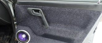
Installation of the lifting device is quite simple. It starts with disconnecting the battery. After this, use a curved screwdriver to unscrew 3 screws, unfasten the door trim latches and remove the door pocket. Using a thin screwdriver, pry off the handle (latch) of the window lifter - the tip of the tool is inserted into the recess between the latch and the socket.
The handle itself is removed. At the next stage, the car door opening handle is dismantled. To do this, use a screwdriver to pry the handle cover and remove it. Now use a screwdriver to remove the 2 fastening screws that were hidden by the cover plate. After this, the handle can be removed without much difficulty. Using a screwdriver, you can also remove the power window button, which serves to lock the door.
After removing 6 pistons, the trim covering the car mirror adjustment mechanism is also removed. As a result, it remains easy to dismantle the door trim. Armed with a 10mm wrench, unscrew the 2 bolts that hold the auto glass clips. Next, 2 nuts securing the lifting mechanism, nuts of the upper and lower fastenings, and 3 nuts securing the lifting mechanism are unscrewed in sequence.
Upon completion of the described stage, it is time to remove the lower guide pin of the lifting device from the door panel. To facilitate and simplify such an operation, the upper pin of the guide must be bent using a screwdriver. Now the entire lifting mechanism can be safely removed through the resulting opening in the door frame.
In order to quickly, efficiently and without problems install a new electric window regulator in the door, you must first make sure that it is in the fully folded position. Otherwise, the entire operation will not be possible.
However, as already mentioned at the beginning, replacing an inoperative device with a new one is most often not particularly necessary. If the contractor can accurately determine the reason why the window regulator refuses to function normally, it can be repaired quite easily.
Removing old window regulators
- Disconnect the negative connection to the battery or use the ground disconnect button.
- Next, carefully remove the door trim. It is fastened with plastic pistons, so there shouldn’t be any problems: just pry up the edge near the piston and pull. As a last resort, then replace the broken fasteners with new ones (they cost pennies).
- Before removing the window lifting mechanism, install the glass in a position in which there is free access to the mounting bolts through the technical hole of the door, and secure it with regular tape.
- Unscrew the bolts that secure the glass.
- At the bottom of the door, unscrew the guide nut.
- Near the window lifter handle, unscrew 3 more nuts. After this, you can remove the mechanism from the door cavity through the largest opening (pull it up).
Connection diagram, restoration of functionality
To successfully repair a power window, you need to know the structure of the lifting mechanism and the principle of its operation. The window connection diagram looks like this.
- Mounting block.
- Ignition switch device.
- Power window switch for front right door.
- Power window switch for rear right door.
- ESPD gearmotor for the front right door.
- ESPD gearmotor for the rear right door.
- ESPD gearmotor for the rear left door.
- ESPD gearmotor for the front left door.
- Power window switch for left rear door.
- Power window switch for left front door.
- Power window on/off relay.
Diagram of electric windows VAZ 2110, VAZ 2111, VAZ 2112, Lada Ten
Electric windows are used to raise and lower door windows and are installed on some cars. These VAZ 2110 cars have a plug in the door trim instead of a window lifter handle, and there are corresponding illuminated switches on the floor tunnel lining.
In the window lift mechanism, instead of a gear reducer, only a drum is installed, into the hole of which the output shaft of the VAZ 2111 gear motor is inserted.
The gearmotor consists of a worm gearbox and a DC electric motor with excitation from permanent magnets. The direction of rotation of the shaft depends on the direction of the current in the armature winding. To protect against overloads, a built-in thermobimetallic fuse is used. The faulty gear motor is replaced.
Voltage is supplied to the switches only when the ignition is on through a relay of type 904.3747-10 located at the rear of the VAZ 2112 mounting block.
Wiring diagram for power windows
1 – mounting block 2 – ignition switch 3 – power window switch of the right front door 4 – power window switch of the right rear door 5 – power window motor of the right front door 6 – power window motor of the right rear door 7 – power window motor of the left rear door 8 – power window motor of the left front door 9 – power window switch of the left rear door 10 – power window switch of the left front door 11 – power window relay A – to power sources B – to instrument lighting switch C – conventional numbering of plugs in power window blocks
Diagnostics of electrical equipment of the Lada 2110 car. Instructions for troubleshooting the lighting system. Repair of the generator and starter of the Lada 2111. Diagram of the Lada 2112 car. Power window lifter. Electrical circuit diagrams for a VAZ 2111, VAZ 2112, VAZ 2110 car.
- Units and electrical circuits of VAZ 2110, VAZ 2111, VAZ 2112,
- Repair of electrical equipment VAZ 2110, VAZ 2111, VAZ 2112,
- Diagram of electric windows VAZ 2110, VAZ 2111, VAZ 2112
© Club of domestic cars Lada. Do-it-yourself repair and tuning of VAZ (Lada) with photos. The portal will help you do the work on modifying and repairing your VAZ car yourself.
Not much time has passed since they began installing electric windows on the VAZ 2110. However, during this short period, many cases of ESP breakdowns and developments in repairing them have already accumulated.
You can, of course, replace the used device with a new one. But you can go another way, especially since the design of the window regulator allows you to restore its functionality independently. By the way, this can be done without much difficulty. The main thing is that the installation/dismantling and repair instructions are strictly followed. But before you get started, it is recommended to understand the types of these devices.
Connecting power windows VAZ-2109
Owners of a VAZ 2109 car can replace power windows with electric windows. On 2109 cars, electric windows can be connected via standard wiring, which already has everything provided for connecting an ESP.
This circuit is used to connect ESP on more “rich” configurations of the nine and it is advisable to use it when connecting independently. Below are diagrams for connecting an ESP with fuse blocks of new and old models.
Wiring diagram for power windows on a VAZ 2109 with an old-style mounting block (17.3722):
- 1 - Mounting block
- 2 - Ignition relay
- 3 — Ignition switch
- 4 — Right door electric window motor
- 5 — Left door electric window motor
- 6 - Right door power window switch
- 7 - Left door power window switch
- K7 - Power window power relay
- A - To terminal “30” of the generator
- B - To the wiring harness block connected to the heater lever illumination display
- B - to the heater lever illumination display
- G - conventional numbering of plugs in the gear motor block
Types of window regulators and the main causes of their breakdowns
Today the following types of window lifters are in use on VAZ:
- rack type (experts consider them the most reliable of all known designs);
- cable;
- plank.
Depending on which company produced the product in question, it can be installed in the car door as standard, or, if it does not fit in size or other technical characteristics, it can be altered without unnecessary problems.
Since both domestic and imported gear motors can be installed on the lift, the described devices, depending on the type and origin of the electric motor, may differ:
- by the speed at which the glass is raised or lowered;
- according to the noise level recorded during operation of the window lifter;
- if possible, its normal operation in winter conditions.
Types of electric windows and which ones are better for the VAZ 2109
ESPs come in various types.
- cable-type (weak and very slow, with the advantage of being cheap and being able to replace the motor separately if it suddenly burns out);
- rack and pinion (a bit weak, based on operating experience - require regular lubrication);
- articulated-lever (work quickly, make little noise, are quite powerful: they can easily cope with frozen glass).
We opt for the latter, called “Pomegranate”. Moreover, the kit of these ESPs includes everything necessary for installation - electrical wiring, buttons, plugs, all the necessary fasteners, rubber cuffs for pulling the wiring from the rack into the door.
There are also “Katran” and “Berkut”, they have a slightly different device and installation is a little more complicated, but according to reviews they are also not bad.
Installation procedure for glass lifting devices
Installation of the lifting device is quite simple. It starts with disconnecting the battery. After this, use a curved screwdriver to unscrew 3 screws, unfasten the door trim latches and remove the door pocket. Using a thin screwdriver, pry off the handle (latch) of the window lifter - the tip of the tool is inserted into the recess between the latch and the socket.
The handle itself is removed. At the next stage, the car door opening handle is dismantled. To do this, use a screwdriver to pry the handle cover and remove it. Now use a screwdriver to remove the 2 fastening screws that were hidden by the cover plate. After this, the handle can be removed without much difficulty. Using a screwdriver, you can also remove the power window button, which serves to lock the door.
After removing 6 pistons, the trim covering the car mirror adjustment mechanism is also removed. As a result, it remains easy to dismantle the door trim. Armed with a 10mm wrench, unscrew the 2 bolts that hold the auto glass clips. Next, 2 nuts securing the lifting mechanism, nuts of the upper and lower fastenings, and 3 nuts securing the lifting mechanism are unscrewed in sequence.
Upon completion of the described stage, it is time to remove the lower guide pin of the lifting device from the door panel. To facilitate and simplify such an operation, the upper pin of the guide must be bent using a screwdriver. Now the entire lifting mechanism can be safely removed through the resulting opening in the door frame.
In order to quickly, efficiently and without problems install a new electric window regulator in the door, you must first make sure that it is in the fully folded position. Otherwise, the entire operation will not be possible.
However, as already mentioned at the beginning, replacing an inoperative device with a new one is most often not particularly necessary. If the contractor can accurately determine the reason why the window regulator refuses to function normally, it can be repaired quite easily.
Alexmtx › Blog › Correct connection diagrams for electric windows (ESP) and glass closers
When you need to install ESP (electric windows) yourself, then, as always, on the Internet it is difficult to find correct and understandable diagrams for everyone. Having experience in radio electronics, I am laying out for everyone the correct and understandable diagrams for connecting an ESP, an intelligent glass closer Pandora DWM-210 (but it is better to install a Sheriff PWM-200), as well as simple closers only for raising the glass, installed in the wire gap on the positive side of the motor.
We take ESP power keys (not trigger (multiplex) from Itelm): a block from Granta, and a new model button from Kalina (it is the power key), since they are the cutest in appearance.
These are, of course, not dual-mode imported buttons, but they will work just as well with an intelligent door closer. We also install the Sheriff PWM-200 type door closer itself. We use thick power wires (shown in bold in the diagrams) >= 1 mm2, while control wires can be used thin = 0.5 mm2.
Power buttons are easy to identify by their contacts - they have thick and flat blades, while trigger buttons have thin pins like needles! Exception! If the buttons are not on the door, but on the center console and thick wires >= 1.5 mm2 are stretched from them to each door, then you can do without a relay, since there is no duplicate button here, and each one has its own door and the drawdowns are minimal. Then you don't have to read further.
Plus +12V must be taken from the fuse block, and not from the ignition, otherwise the automatic window closer will not work when arming. It is better to take the weight from the bolt behind the mounting block, and not in the door, since the contact in the door may not be very good. Although the door contact is also good if the car is not old. Take tinned terminals.
Connection diagram for power window lifter button "AVAR"
Diagrams for connecting the backup button on the driver's door to the main button on the passenger door
When installing two buttons on one window regulator, they are usually installed in series (or in parallel, but then they must be decoupled via a relay).
The main button is the button that controls the power window of the door on which it is installed. The duplicate button is the driver's button, which additionally controls another window regulator from the driver's seat.
Daisy chain connection (for trigger buttons)
We connect the output of additional button 1 in the driver's door to input 6, and output 7 to input 3 of the main button on the passenger door. We cut the wires in the block connecting contacts 5-6 and 6-3. The minus of contact 5 now goes only to the backlight, and contacts 6 and 3 now take output from additional buttons 1 and 7 of the driver's door. Installation in parallel will result in short-circuiting during lifting and lowering. Power wires are highlighted in bold.
Parallel connection (only for power buttons)
Since with a serial connection you still can’t do without a relay, it is better to make a button duplication circuit in parallel, decoupling the main button from the backup button through two 5-pin relays: the wires from the main button next to the driver’s ESP motor go directly to the 88th contact of the relay and from pin 30 directly to the engine, and long wires from the backup button go to pin 85 of the relay winding, and the relay feeds a powerful plus to the passenger’s ESP engine.
A parallel connection for power buttons is preferable, since there is no need for a relay on the main (passenger) button (the wires here are short), and we thereby eliminate unnecessary clicking of the relay when the main button on the passenger door operates. For non-power (trigger) buttons, in this case, you will definitely have to use 2 more extra relays to relieve the load on the passenger button (therefore, a serial connection is always used for trigger buttons). Further, everywhere in my circuits a parallel connection is used, since all the buttons are power
.
Connection diagram for multiplex (low-current) ESP button
ESP connection diagram when the multiplex button closes the contacts to ground
Dimensions of the installation location for the ESP “AVAR” buttons
Glass closer Pandora DWM-210
What it gives: - full glass travel in one short press (“one touch”) - BUT DOES NOT WORK ON 2 GLASSES AT THE SAME TIME (since the module has only one sensor for electromagnetic noise of the motor, current and time); — stopping the glass in any position by pressing again in any direction; — automatic stop of the glass when it encounters an obstacle in the window opening; — automatic shutdown of ESP motors when current is exceeded; — automatic closing of windows when arming the car; — automatic opening of the windows when disarming to the previous position before arming, if the parking lasted no more than 20 minutes. (The rev counter works rather conditionally and may leave the windows closed or not closed enough). The closer is installed in the driver's door.
ATTENTION! When you hold the button, the closer does not use its relays
, which take the plus (through a 20A fuse) and minus from the closer, but sends all the current directly from the button to the motor, so you need to install a relay after leaving the button with long wires!
Apparently this was done so that if the door closer fails, you can always close the window by simply holding the button. When you briefly press
the button, the door closer with its relays is activated and closes the glass.
Place the relay only at the input to the closer from the output after the duplicate button!
If this is not done, then due to subsidence along the long wires of the sequential connection of the buttons, the passenger window will barely move.
The output of the closer must be connected directly to the motor without a relay, otherwise the detection of electromagnetic noise from the motor will not work and the closer will not work!
At the output of the driver's power button, relays are not needed, since all the power wires there are short.
It is ideal to install 2 door closers on each door, as is standard on foreign cars - then the AUTO mode will be on 2 doors at once in parallel, and not alternately. In addition, you will not need to pull 2 extra thick wires to the motor from the driver's door to the passenger's door. If I had known right away that the Pandora DWM-210 is such a Ketai crap without its own relays in the power part of the closer, I would have purchased and installed a Sheriff PWM-200
, in which the power part is clearly separated from the control part and, moreover, you can close two windows at the same time in one touch! So it's definitely better!
This is interesting: What to do if the “CHECK” lights up?
The power windows are turned on by the module sequentially after a trigger pulse is given: first the driver's door, then the passenger door, and the next channel is turned on after the previous one has been completed. If the glass is already closed, the module will immediately switch to the next channel. Closing control is carried out by electromagnetic noise from the motor.
When the power is turned on, the closer module needs to be calibrated based on the protection current. You need to press SHORTLY to lower each glass all the way, then raise it in the same way. At the same time, the closer remembers the characteristics of the engine. The control signal for closing and opening is NEGATIVE ONLY. Control can be done from the central locking or from an additional alarm channel. It is necessary to connect the control output of the security system to the “White/Red” (windows up) and “White” (windows down) terminals of the module, respectively. The duration of the trigger pulse must be at least 500ms. (0.5 sec.). Attention: in older releases the wires of the buttons and motors were swapped - for such blocks we swap the wires under the numbers: 9 2, 16 20, 15 10, 14 19, 13 18. On the latest Pandora (November 2011 and newer) the diagram is correct, so that there is no need to swap wires from buttons and motors!
Closer in wire break for lifting ESP
Addition dated 10/05/2014 at the request of SIBUR95. There are closers that are connected to the break in the lifting wire that goes to the ESP motor. There are 2 wires coming from the closer and they are constantly closed in it. When you turn on the closer, they break and + appears on one, and nothing on the second. On GREEN, when the door closer is operating (arming), a plus appears and it goes to the engine, and a minus goes from the button (or from the relay from contact 88 to 30) to the engine. When the closer does not work, it simply passes current from BLUE to GREEN by closing its relay and that’s it.
Here the circuit differs only in that the minus of the motor is connected directly to the button (or to the relay, if the button is duplicated), and the plus also passes through the closer, and the relay is located at only one input to the closer, thereby not interfering with the detection of engine noise.
You can also make a button duplication circuit not in series, but in parallel on two 5-pin relays. The advantage is that a series circuit is eliminated; the relay will not click again from the main button, which is closer to the engine (with short wires), but only from the backup one. The downside is that for non-power (trigger) buttons in this case you will have to use 2 extra relays (relays 3 and 4 in the diagram).
Scheme for any number of duplicate buttons and number of doors
You can put as many buttons in parallel as you like and simultaneously press them in different directions - a short circuit is impossible from the circuit design! In a situation where we press the up button on the main button, and the down button on the backup button, it will simply stop, since both power lines will have the same potential.
The only difference between the closer is the presence of an MK between the buttons and power relays. The advantage of the circuit is that the power switching is in one place, there are no losses in the harnesses and on the buttons, there is a minimum of “pulling” of wires - 2 in total per channel + ground. In good quality, full-featured closers, the power part and control lines are implemented in the same way + the functions of “auto-detection” of active control levels are also added.
If a door closer of the PWM-200 on Sheriff type with low-current control is installed, then there is no point in these relays, since they are already mounted in the door closer. This circuit with a relay is for understanding the essence of reverse control and duplicating buttons in parallel. Power outputs both in the central locking system and in the door closers are implemented in exactly this way.
It is also advisable to connect non-polar electrolytic capacitors of 22 uF 25V to the contacts of the ESP motors in order to smooth out the range of current ripples in the power channel of the closer so that it works correctly even when the motors are worn out and does not suddenly stop the glass when opening and closing.
The usual scheme of duplicate buttons for 4 doors
Duplicate buttons must also be supplemented with two 5-pin relays (they are not shown in the diagram).