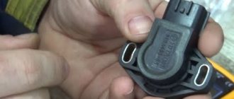
An analogue of a modern car is a device made up of many components and assemblies. Deviations in the operation of the smallest component can lead to quite serious problems. The throttle position sensor (TPS) is one example of this type of component. And adjusting the throttle valve is an integral element of routine diagnostics of any car.
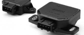
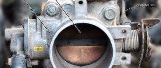
The throttle valve is presented in the form of an air valve, the functional task of which is to regulate the amount of air entering the engine. The fundamental features of the unit include a change in the cross-section of the air channel. When it is open, air flows smoothly through the intake manifold. The throttle position sensor, located here, determines the opening angle. This function is carried out through its communication with the engine control unit. The signals coming from the sensor contribute to the issuance of a command from the control unit to increase the amount of injected combustible mixture. Thus, the working mixture is enriched, and the engine operates closer to maximum speed.
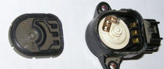
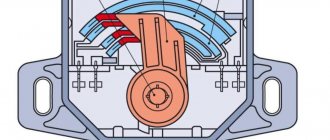
Its sensor includes two types of resistors:
- Single-turn constant.
- Variable.
The sum of their resistance is approximately 8 kOhm. The reference voltage here is supplied to one of the outer terminals from the controller, and the second terminal is connected to ground. Thanks to this, a signal is sent to the controller, informing about the current position of the throttle valve. The value of the pulse voltage depends on the position level of the element, the standard interval of which is 0.7 to 4 W.
Important: the open state of the unit indicates the pressure level in the intake system of the vehicle is similar to atmospheric pressure; when closed, this value decreases to the vacuum state.
Execution Sequence
Note. The operation is shown on a car with engine 21114; on cars with other engines it is performed similarly.
2. On engines 2112, 21124 and 21114
remove the decorative trim of the engine (see “Decorative trim of the engine - removal and installation”).
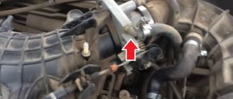
3. After loosening the three clamps, remove the air supply hose to the throttle valve.
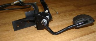
4. We control the position of the throttle valve: with the gas pedal pressed (all the way to the floor), the throttle valve should be completely open.
. and when the pedal is released, it is completely closed.
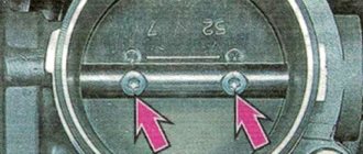
5. The position of the closed damper is adjusted with a stop screw, rotating it with a slotted screwdriver with a thin blade. The damper should close completely, without jamming.
The position of the open throttle valve is adjusted by changing the tension of its drive cable.
Warning! When performing this operation, do not overtighten the cable, as this may damage the drive elements.
6. On engines 2112, 2111 and 21114
13 mm
wrenches by rotating the adjusting nuts (1) and (2), we adjust the cable tension (small sagging of the cable is allowed in the area between the throttle valve drive sector and the end of the shell).
a) Use pliers to remove the locking plate of the throttle cable sheath.
b) By moving the cable sheath in the rubber holder, we adjust the cable tension (in the area between the throttle valve drive sector and the end of the sheath, a slight slack in the cable is allowed).
V. We install the locking plate in place.
7. Check the operation of the drive. If necessary, repeat the adjustment.
Source
Nature of faults
Malfunctions or incorrect adjustment of the damper can be manifested in the following features:
- uncertain or difficult engine starting;
- increased fuel consumption;
- increased idle speed;
- failures when accelerating;
- Jerking when switching.
Adjusting the throttle valve VAZ 2110
NOTE Adjustment of the throttle valve drive is shown on the VAZ 21124 (1.6i) engine. Features of adjusting the throttle valve drive on the VAZ 2112 (1.5i) engine are indicated in the text.
RECOMMENDATION It is necessary to adjust the throttle valve drive after replacing the drive cable, after removing and installing the throttle assembly, and also after performing work related to dismantling the intake module. Throttle actuator adjustment may be necessary if the vehicle's engine may not be able to produce maximum power due to the throttle valve not being fully opened.
An assistant will be required to perform the adjustment work. Adjustment sequence
1. We prepare the car for work (see paragraph 2a Preparing the car for maintenance and repair).
2. Remove the decorative trim of the engine (see Decorative trim of the engine - removal and installation). 3. After loosening the three clamps, remove the air supply hose to the throttle valve. 4. We control the position of the throttle valve: with the gas pedal pressed (all the way to the floor), the valve should be completely open,... .
and when the gas pedal is released, it is completely closed. 5. The position of the closed throttle valve is adjusted with a stop screw, rotating it with a slotted screwdriver with a thin blade. The throttle valve should close completely without sticking. The position of the open throttle valve is adjusted by changing the tension of its drive cable. WARNING When adjusting the open throttle valve, do not overtighten the cable, as this may damage the drive elements.
6. On the VAZ 2112 (1.5i) injection engine:
Using two 13 mm wrenches, rotating the adjusting nuts (1 and 2), we adjust the cable tension (small sagging of the cable is allowed in the area between the throttle valve drive sector and the end of the casing).
On the VAZ 21124 (l.6i) injection engine:
a) Use pliers to remove the locking plate of the cable sheath.
b) By moving the cable sheath in the rubber holder, we adjust the cable tension (in the area between the throttle valve drive sector and the end of the sheath, a slight slack in the cable is allowed). c) Install the locking plate in place. 7. Check the operation of the throttle valve drive. If necessary, repeat the adjustment. 8. Install all the removed parts on the car in the reverse order of removal.
Idle speed regulators IAC for ZMZ 406 car
Among the many units related to transport, the idle air control deserves special mention. The device provides:
- equalizing the number of revolutions when the engine is running without load;
- eliminating pressure fluctuations of the oxidizer entering the engine during sudden throttle movements;
- control of oxygen filling of the mixture at idle speed;
- controls the force of air flow when the engine warms up at auto start.
For Russian injection engines of the ZMZ 4213, 405, 406, 409 series installed in UAZ and GAZ cars, the RXX-60 is used.
Device РХХ-60
The function of idle air regulators is to control the free volume of the engine air duct section. The procedure is performed with a valve equipped with an electric drive. It is controlled by a microprocessor control unit for vehicle components, which generates the required number of pulses to change the position of the rotary valve. In total, the ECU provides 240 node positions for the valve between its full opening and closing. Calibration is carried out on a special stand for each IAC.
The idle speed regulator is located on the line of atmospheric gas supply, bypassing the damper controlled by the throttle. When it is closed, the engine is supplied with oxygen through this channel.
When the starter is turned on, the idle speed regulator completely opens the gas channel. When the engine is started and already warmed up, but not yet loaded, the valve allows up to 35–45% of the air mixture through the bypass paths. When the throttle moves, the IAC regulates the volume of oxygen entering the cylinders, decreasing and increasing its additional amount.
The regulator receives power supply from the on-board network. The electromagnetic windings begin to work by connecting them to the vehicle ground through the ECU.
Technical characteristics and connection diagram
Characteristics of the idle air regulator used in Gazelles, UAZs and Volgas with 406 series engines:
- throughput: 60 kg/h;
- winding control channel frequency: 125 Hz;
- power supply: 6–18 V;
- induction of the windings of the motor controlling the valve with a power supply of 100Hz:
The device is connected to the engine electronic systems according to the following diagram:
The middle terminal of the contact connector is common. The first is used to power the opening winding, the third controls the closing of the valve.
Signs of regulator malfunction and possible causes
There are several signs in engine operation that indicate problems with the idle speed controller:
| Fault lamp and codes | Symptom | Possible causes and solutions |
| Check Engine won't turn on | The engine gives increased speed when warmed up and idling. | The movable shutter of the secondary air regulator can be coked; it is recommended to wash it with kerosene and then dry it |
| If starting the engine is possible with the PXX-60 hose blocked, the oxygen mixture is likely to pass through the throttle valve | ||
| Check Engine won't turn on | The engine starts, but it turns off immediately, or becomes possible only when the accelerator pedal is half depressed | You need to make sure that the air channel is clean, and if it is dirty, remove plaque from the walls using kerosene |
| Possible IAC malfunction | ||
| Check Engine Light Active | Self-diagnosis codes 161-166 or 0505-0509, 0511, 1509,1513-1514, 1750-1755, depending on the ECU used | Electrical problems |
Fault codes can be obtained by connecting pins 10 and 12 of the diagnostic connector located in front under the hood. The number of flashes of the Check Engine light that begin to occur after the ignition is turned on, and the pause between the series, will give the required numbers.
Deciphering the codes when the Check Engine warning light is active:
| Code | Possible cause and fix/search methods |
| 161–166, 1750–1755 | The IAC is disconnected from the ECM; broken contacts 37, 14; short circuit between 4 and/or 26; between them and the body; malfunction in the computer; failure of the regulator coils; Short circuit on windings |
| 0505 | Problems in the power supply circuits and interfaces of the РХХ-60 |
| 0506–0507 | Interference in the operation of the regulator - low or too high speeds |
| 0508, 1513 | Short circuit between the control circuits of the IAC electric drive and ground |
| 0509, 1513 | Short circuit between the control circuits of the IAC electric drive and the power supply network |
| 0511 | Open circuit in the motor control circuits |
| 1509 | Overload of motor control circuits |
The most relatively difficult to detect faults are mechanical damage to the internal device. With them, everything is fine electrically, but the moving curtain does not respond to incoming impulses. The problem here could be a physical break in the magnets or a detachment of the rod. The cause is extreme mechanical stress during an accident or a strong blow to the regulator.
Whatever similar symptoms appear in the car, it is worth first checking the integrity of the connecting lines and the functionality of the ECM sensors.
Testing РХХ-60
It is quite simple to determine the functionality of the electrical part of the idle air regulators. First, disconnect the IAC from the interface wires and air ducts of the car engine. The plus from the battery is supplied to the center line of the regulator. The minus touches one by one to the outermost inputs of the connector. In a working device, when connected to one contact, the valve will open completely, and when touching the other, it will close.
Next, the performance is checked with a multimeter. There should be a resistance of about 12 ohms between each of the outer contacts and the center line. A short circuit between any of the three lines and the regulator body is also unacceptable. The resistance, when checking for short circuit, is determined by the multimeter to be at least 1 MOhm.
Analogs from different manufacturers
The idle speed regulator РХХ-60 for engines of the ZMZ-406, 4213, 405, 409 series (original code 0280 140 545) is produced by many manufacturers. Here are some of them:
| Manufacturer | Catalog number |
| MetalPart | MP-406-1147051-02 |
| PEGASUS | 406-1147051-02 |
| Certronic | |
| UAZ |
Replacement procedure
- Disconnect the interface cable from the idle speed control.
- We remove the suitable air tubes by loosening the clamps holding them with a screwdriver.
- 10, use a wrench to unscrew a pair of bolts securing the regulator to the engine body.
- Next, remove the clamp holding the device and the rubber base underneath it.
Assembly is carried out in reverse order. To avoid accidental mistaken connection of the regulator sides to the bypass air supply system, the upper inlet pipe on the RXX-60 is wider than the lower one.
vote
Article rating
