Installing a start-stop button instead of the ignition switch with your own hands:
Every person strives to make their life easier. And the car enthusiast in this sense is no exception. He constantly tries to save himself from performing all sorts of routine operations, such as turning the ignition key, for example. To avoid fiddling with keys every time, car enthusiasts install start/stop buttons in their cars. But is it really safe? And if so, how to install such a device on the ignition switch? Is it possible to do this with your own hands, and most importantly, at minimal cost?
Why change the backlighting of individual buttons on the VAZ 2114 dashboard
On the VAZ 2114, the illumination of the buttons for controlling the dimensions, low beam, front and rear fog lights, as well as the rear window heating is green from the factory. Over time, many owners get tired of this glow and there is a desire to replace it, make it non-standard. After making a decision about such modifications, you need to decide: do this work yourself or contact the service. Since the process of replacing button backlighting is not a complicated procedure, in most cases, car owners carry out such an upgrade with their own hands.
The standard green backlighting of the buttons gets boring over time.
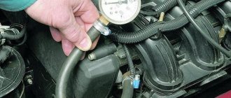
How the start/stop button works
The start/stop device operates on the simplest principle: first, the car alarm is turned off, then the driver depresses the brake pedal, then presses the button.
Car-installed start/stop button
The starter operates for one or two seconds, after which the car starts. If the engine needs to be turned off, the driver again squeezes the brakes all the way and clicks the button.
Advantages and disadvantages of the device
First, we list the advantages of the “start/stop” mechanism:
- The driver no longer needs to use the ignition key every time he needs to start the engine. All it takes is a simple click;
- you can mount the “start/stop” anywhere. This means the car will become a little more comfortable;
- there are special schemes in which the start/stop button is connected to the immobilizer or alarm system, which is an additional security measure that prevents car theft;
- If the driver leaves the car for a short time, he can lock the car by simply pressing a button on the door. In such situations, there is no particular need to set the car alarm, therefore, there is a slight saving of time.
But there were some downsides too:
- To start the engine, the driver must sit in the car and press the brakes. Getting used to this feature of starting the engine can be difficult, especially for novice car enthusiasts;
- if the driver decides to install an alarm with an auto-start function on a car with a button (to warm up the car in winter, for example), then problems may arise with this, which, fortunately, can be solved. The driver will just need to have a couple of key fobs with him. One of them will have to be given to alarm installers so that they can disassemble it, take out the microcircuit and put it in the car. After this, the current will be supplied only at the moment the engine starts. But for all this, the car owner will have to seriously pay extra to the craftsmen;
- If a button is already installed on the car, but there is no alarm yet, then installing it will cost the driver more, sometimes twice as much.
Reworking the low beam button
It, like an abrasive, increases the friction force, which creates resistance to glass movement.
Installing PTF provides better illumination of the roadside and side markings, reducing the risk of leaving the road. Some motorists are of the erroneous opinion that fog lights with high lighting efficiency can only be yellow. These grooves tend to become clogged with dirt.
This allowed additional parts to be kept to a minimum and simplified the design.
A well-known situation arises - the blinding of drivers of oncoming vehicles, which increases the risk of an accident. This is due to the geometry of the lifting mechanism. Is this really true?
We recommend: Era switch how to connect
Manual window lifters
There are 8 clips installed around the entire perimeter of the door. Replacement cost Replacing VAZ window regulators is cheaper than installing electric mechanisms to replace manual ones.
They create fewer electrical problems, but the inconvenience of using them is that while in the driver's seat, it is impossible to open the window on the passenger side without being distracted from driving. The front left window regulator fails faster due to more frequent use.
Registration
Location of relays and fuses of the old model 1 - relay for turning on the headlight cleaner K6; 2 — rear window washer time relay K1; 3 - relay breaker for direction indicators and hazard warning lights K2; 4 — windshield wiper relay K3; 5 — contact jumpers in place of the relay for monitoring the health of the lamps; 6 — relay for turning on the heated rear window K10; 7 - spare fuse; 8 — relay for turning on the main beam headlights K5; 9 — relay for turning on the low beam headlights K11; 10 - fuse; 11 — relay for switching on the electric motor of the engine cooling system fan K9; 12 - relay for turning on the sound signal K8. In the cabin, in a place convenient for the driver, a button for turning on the PTF is installed. The grille with the speaker is removed from the standard front panel. To illuminate the central locking button 4. On the driver's door there is a block of buttons that control all windows that have an electrical connection for VAZ power windows
It consists of a roller and a gearbox, which is rotated either by a handle or by an electric motor if there is an electrical circuit for the VAZ window regulator. Fill the upper part of the resulting pads with silicone. The mentioned wires are pulled to the fuse block from the fog light relay. I have not yet figured out how to overcome this problem, so I have disabled the microswitch for now and use the central lock button. Absent 8. VAZ 2110,11,12 CONNECTION OF FRONT FOG LIGHTS ACCORDING TO STANDARD
About the options for installing the start/stop button
Now there are a lot of different connection schemes for the start/stop mechanism, each with its own characteristics. We list the most popular options:
- diagram involving the use of an ignition key. When using this option, it is impossible to start the car without a key: the driver first turns the key and only then presses the button;
- modification without an ignition key. The engine starts by simply pressing a key. This is very convenient, but if the device is installed incorrectly, the machine can become easy prey for intruders;
- circuit with a short press of a button. The driver presses the button for only 1–2 seconds, the starter makes several revolutions and turns off immediately after starting the engine;
- options with a long button press. In this case, the owner can hold the button as long as he wants, and the starter will rotate until the engine starts;
- a circuit that turns on the ignition only after pressing a key;
- a modification in which the ignition is turned on 1 second before the starter.
In addition, combinations of several of the above options are possible: it all depends on what exactly the car owner wants to achieve. However, installation of such combined circuits requires certain knowledge of automotive electrical equipment.
Checking and replacing steering column switches on a VAZ 2170 Priora
- Repair manuals
- Repair manual for VAZ 2170 (Priora) 2004+.
- Checking and replacing steering column switches
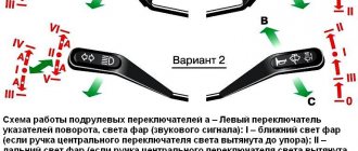
The steering column switch assembly consists of a connector secured with a clamp to the steering shaft bracket and two switches with levers.
The left switch turns on the turn signals and switches the headlights, the right switch controls the windshield washer and wiper, as well as the trip computer in the instrument cluster. The switches are secured in the connector with latches.
| . Positions of the steering column switch levers |
The positions of the switch levers are shown in, the contacts closed in this case are shown in table. 10.7.
Table 10.7 Contacts closed at different positions of the steering column switches
* Non-fixed lever positions.
Contact numbers of the turn signal and headlight switch
Wiper and washer switch contact numbers
You will need a tester.
1. Disconnect the wire from the negative terminal of the battery.
2. Remove the steering column casing (see “Removing and installing steering column casings” ).
3. Remove the steering wheel (see “Removing and installing the steering wheel” ).
| 4. Disconnect the connectors with wires from the left steering column switch... | 5. ...from the trip computer control block... |
| 6. ...and from the right steering column switch. | 7. Squeeze the plastic clips of the left steering column switch on both sides... |
| 8. ...and remove the switch from the connector. | 9. Similarly, remove the right steering column switch. |
10. To check the switches, connect a 12 V test lamp to the corresponding contacts indicated in the table. 10.7 (here is shown checking the inclusion of the left turn signal). Move the switch lever to the position corresponding to the contacts being tested - the lamp should light up. Otherwise the switch is faulty.
11. Install the steering column switches in the reverse order of removal.
↓ Comments ↓
1. Car structure
1.0 Car structure 1.1 General information about the car 1.2 Passport data 1.3 Car keys 1.4. Controls 1.5. Heating and ventilation of the cabin 1.6 Ensuring a comfortable air temperature in the cabin 1.7. Doors 1.8. Passive safety equipment on the car 1.9. Seats
2. Recommendations for use
2.0 Recommendations for use 2.1. Safety rules and recommendations 2.2 Running in the car 2.3 Operating the car during the warranty period 2.4. Preparing the car for departure
3. Problems along the way
3.0 Malfunctions along the way 3.1. The engine does not start 3.2 Malfunctions of the fuel injection system 3.3 Idle speed has disappeared 3.4. Interruptions in the operation of the 3.5 engine. The car moves jerkily 3.6 The car accelerates poorly 3.7 The engine stalled while driving 3.8. Oil pressure dropped to 3.9. Engine overheating 3.10. The battery does not recharge 3.13. Knocks in the engine 3.16. Wheel puncture
4. Maintenance
4.0 Maintenance 4.1. General provisions 4.2. Inspection work 4.3. Lubrication and filling works 4.4. Diagnostic work 4.5. Repair and adjustment work
5. Engine
5.0 Engine 5.1 Design features 5.2 Possible engine malfunctions, their causes and solutions 5.3 Useful tips 5.4 Checking compression in the cylinders 5.5 Removing and installing the decorative engine casing 5.6 Removing and installing the engine splash guard 5.7 Installing the piston of the first cylinder to the TDC position of the compression stroke 5.8 Replacing the drive belt gas distribution mechanism and tension roller 5.9 Replacing the power unit supports 5.11. Replacing engine seals 5.13. Engine cylinder head 5.15. Engine repair 5.16. Lubrication system 5.17. Cooling system 5.18. Power supply system 5.19. Design Features
6. Transmission
6.0 Transmission 6.1. Clutch 6.2. Gearbox 6.3. Front wheel drives
7. Chassis
7.0 Chassis 7.1. Front suspension 7.2. Rear suspension
8. Steering
8.0 Steering 8.1 Design features 8.2 Possible steering malfunctions, their causes and solutions 8.3. Steering column 8.4. Steering linkage 8.5. Steering gear
9. Brake system
9.0 Brake system 9.1 Design features 9.2 Possible malfunctions of the brake system, their causes and solutions 9.3 Bleeding the brake system hydraulic drive 9.4 Removing and installing the vacuum brake booster 9.5 Replacing the brake pedal axle bushings 9.6. Main brake cylinder 9.7. Front wheel brakes 9.8. Braking mechanisms of the rear wheels 9.9. Pressure regulator 9.10. Brake hoses and tubes 9.11. Parking brake
10. Electrical equipment
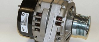
10.0 Electrical equipment 10.1 Design features 10.2. Battery 10.3. Mounting block (relays and fuses) 10.4. Generator 10.5. Starter 10.6. Ignition switch (lock) 10.7. Electronic engine control system (ECM) 10.8. Ignition system 10.9. Lighting, light and sound signaling 10.10. Windshield cleaner 10.11. Washer reservoir 10.12. Electric fan of the engine cooling system 10.13. Electric motor of the heating and ventilation system fan 10.15. Cigarette lighter 10.16. Instrument cluster 10.18. Electronic anti-theft remote control system 10.19. Immobilizer 10.21. Replacing sensors and switches
11. Body
11.0 Body 11.1 Design features 11.2 Possible body malfunctions, their causes and solutions 11.3 Removing and installing windshield frame lining 11.4 Removing and installing soundproofing upholstery in the engine compartment 11.5. Removing and installing bumpers 11.6 Removing and installing the fender liner and protective wing cover 11.7 Removing and installing the front fender 11.8 Removing and installing decorative sill trims 11.9. Hood 11.10. Trunk lid 11.11. Doors 11.12. Seats 11.13. Seat belts 11.14. Rear view mirrors 11.15. Interior fittings 11.16. Instrument panel 11.17. Heater 11.20. Body care
12. Applications
12.0 Appendix 12.1 Appendix 1. Tightening torques of threaded connections, Nm 12.2 Appendix 2. Fuels, lubricants and operating fluids 12.3 Appendix 3. Nominal filling volumes 12.4 Appendix 4. Basic data for adjustments and monitoring 12.5 Appendix 5. Spark plugs used on vehicles 12.6 Appendix 6. Lamps used on a car 12.7 Appendix 7. What you need to have in a car 12.8 Appendix 8. Tools used when repairing a car
13. Electrical diagrams
13.0 Electrical Diagrams 13.1 Diagram 1. Instrument Panel Harness Connections 13.2 Diagram 2. Vehicle Front Wire Harness Connections 13.3 Diagram 3. Engine Electronic Control System (ECM) Harness Connections 13.4 Diagram 4. Vehicle Rear Wire Harness Connections 13.5 Diagram 5. Light Harness Connections license plate light 13.6 Diagram 6. Left front door wiring harness connections 13.7 Diagram 7. Right front door wiring harness connections 13.8 Diagram 8. Rear door wiring harness connections
How to install a mechanism in a car
Before you begin installing the start/stop button, it is necessary to carry out certain preparatory work, which will depend on the car model. The ignition switch is removed from the car. And if the design of the car does not allow this, then a small hole is made on the dashboard, next to the lock. To cut through it, any available tool will do: a knife or an ordinary household soldering iron. This hole will give access to the wiring (you can make a plug for it later).
Next, we consider the simplest and most accessible option for installing a button, which will work like this: the first press of the key in combination with the pressed brake pedal will start the engine, the second press will turn it off.
The simplest do-it-yourself start/stop button connection diagram
Device installation procedure:
- the relay is connected with its positive contact to the positive terminal of the battery (this is the brown wire);
- the enabling positive signal of the relay is also output to the positive terminal of the battery;
- the general minus is output to ground;
- the working contacts from the load relay are set to 12 volts (this is the blue wire);
- the control negative signal is output to the “start/stop” button;
- the enabling positive signal is not output anywhere.
The simplest connection diagram for the start/stop button allows you to install it in about half an hour
The operation of the device comes down to creating 3 connection points in the car: one should be in the ignition block, the second should be on the brake pedal limit switch, and the third should be on the control wire.
How to properly connect a start/stop device to a car
In other schemes, the above principle remains the same: there is a button with multi-colored wires that are difficult to confuse. If a problem may arise, it will be with the yellow wires, since on some models of buttons there are three of them. Here's what you need to remember: the thin yellow wire on the harness controls the brakes. The two remaining wires go to the ignition.
A car enthusiast may also encounter a purple wire. These wires usually start the engine. The red wire goes to the negative terminal of the battery, the black wire to the positive terminal. In a diagram it might all look like this:
Connection diagram, providing for the use of a ready-made set of “start/stop” buttons
It was not by chance that we started talking about the color of the wires. Most car enthusiasts prefer not to bother with connecting the wiring to the button, but buy a ready-made kit right away: a “start/stop” mechanism with all the necessary wires and a circuit. Insulation colors in kits from different manufacturers almost always have the same meaning, so there is little to no confusion.
Start/stop button complete with wiring
The procedure for replacing and soldering the necessary microcircuits
First, a few thoughts. This portal is primarily TECHNICAL for me and, as a technician, I am interested in various modifications, especially in terms of electronics. Really interesting material about alterations and necessary modifications constantly has to be painfully searched for. The records found about modifications and alterations turn out to be both hastily (the majority) and very competent with the corresponding investments. I have no right to criticize anyone, but I am a supporter of competent and careful alterations. When I started looking for information about overexposing buttons, I found a lot of records with reports on the work done, but something was missing everywhere. That is why I decided to leave my post, combining here all the necessary (in my opinion) information.
So, what is the component of the correct overexposure of LED-backlit buttons?
Making changes to the schema
An LED is not an incandescent lamp and has a completely different operating principle. For an LED, the current passing through it is important, so selecting a current-limiting resistor is point No. 1. It should be noted that the parameters of LEDs also differ depending on the color of the radiation and their standard size. Even LEDs that look the same can have significant differences.
Accurate execution of work
Vandal soldering or an attempt to “shove something that cannot be shoved” into the criterion of correct overexposure does not fit this criterion. Replacement elements are selected exactly the same size as in the buttons themselves. The most accurate soldering. It is also correct not to leave traces of the sting on the plastic.
Understanding the purpose of button backlighting
This is very important, because in many entries I did not see this from their authors. I didn't see it at all. The backlight in the buttons is clearly not intended to burn out the eyes and illuminate the interior. Despite this level of light, many write that it is not bright enough.
Combination of button illumination with interior design
A controversial point, but... The green backlighting of the buttons goes well with the green backlighting of the instrument panel, but it doesn’t go well with the color of the car. Everyone has their own tastes and everyone has their own choice, but personally, I would never install blue LEDs in Vinishko. This point is a matter of taste.
My vision of the correct replacement of buttons is exactly this. If you disagree, leave a comment. Always open to criticism and discussion.
The new type of buttons with indication use SMD LEDs and resistors. The standard size of LEDs is always 0805, but resistors come in both 0805 and 1206. To find out which ones you have installed, you need to remove the top cover of the button. If you do not see resistors on the board, this means that 1206 resistors are soldered on the back side of the board. Regardless of the color of the light, the button illumination LED consumes 6mA at a voltage of 12.55V, the power-on LED consumes 16mA at the same voltage. I obtained this data experimentally on different buttons. From this I conclude that the button manufacturers determined the brightness of the emission only by the current consumption, therefore, during the modification, all other parameters of the LED will not be used.
Before starting work, it is advisable to figure out what you need to buy. I used a calculator for calculating a resistor for an LED (for example, the ElectroDroid application) and the parameters of commercially available LEDs (in this case, the drop voltage is sufficient) to calculate the resistor for your LEDs for a current of 6mA and 16mA, respectively. I went further and decided to find out the real value of the voltage drop of the purchased LEDs using Transistor Tester, and then I purchased the necessary resistors.
The whole process with photos
In this way, the voltage drop value of a particular LED is determined
Having received the calculation results, you can purchase the necessary components and prepare the buttons. To remove the buttons, it is better to remove the front part of the dashboard (no need to try to pick them from the front), disconnect the pads from the buttons (you can mark them first if you wish), clamp the petals on the sides that hold the button and push it towards you. Repeat this operation with all buttons preparing for overexposure. If you have worn out buttons, put them aside for donation. At the end of the post you will understand why.
I collected some of the test subjects, they will soon shine with new colors
Next, we proceed to disassembling the buttons themselves. It's best to start from the top of the button. To do this, pry up the button cover latches with a small screwdriver or other flat object and remove it.
Pry up the latches of the button cover and remove it by moving it towards you
Before us is the following picture:
What's under the button cover?
With this method you can determine in advance whether you are lucky or not. The fact is that the new type buttons come in two varieties: those with a backlight board simply put on the contacts, and those with a backlight board soldered to these same contacts. There is also a hybrid version, where conductors are soldered to the board and touch the contacts inserted into the button. We'll talk about this button sometime in future posts.
Next, you need to remove the moving part of the button from the base. To do this, you need to use a flat object to bend the body on the sides to release the latches and pull the moving part towards you.
Here and on the opposite side we unbend the body and push the moving part towards us
This is the picture:
This is how the base of the button and the moving part look separately
Pay attention to the button lock and spring, do not lose them!
The next step is to remove the backlight board:
- For buttons without soldered contacts, push the contacts out from the side of the board and pull them out, after which the board should fall out.
- For buttons with soldered contacts, the situation is a little more complicated. It is necessary to simultaneously pull the contact and heat the soldering area without damaging the plastic. When the solder melts, the contact comes out of the button without any problems. We repeat the steps for all contacts, after which we remove the board. At this stage, you can remove excess solder from the contacts on the boards in advance for easy installation back.
I soldered the contacts using this method: holding the contact, simultaneously pulling the moving part in the other direction and at the same time heating it with a soldering iron. Immediately after the solder melted, the contact went out
All buttons are prepared, disassembly takes a few minutes.
Test subjects are ready
Well, here we come directly to the goal of our work. Further, you don’t need a lot of text, you only need skills in working with soldering equipment. By this moment, the soldering hair dryer (or, in extreme cases, a soldering iron) should be heated. We unsolder the LEDs and resistors and solder new ones in their place.
Below are some photos of the replacement process:
Please note that the LED has an anode and a cathode. This is kind of a plus and a minus. If you mix it up, the LED will not light up! The existing diodes on the board, connected parallel to the LEDs in the opposite direction, perform a protective function. When soldering, we rely on the cathode designations on the LEDs and on the board (if any)
Having finished soldering the elements, it is advisable to check the correct operation of the backlight before assembling the button. To do this, we apply a voltage of 12-14V to the necessary contacts and make sure that it is working.
We assemble the button in reverse order.
Button with redesigned backlight. The board is in place.
This completes the overexposure of the buttons. The result was a soft and natural light for them. It's a pity that the quality of the pictures leaves much to be desired. LEDs operate in the mode allowed for them. Since the same LEDs and resistors designed for the same current were used for all buttons, the backlight turned out to be even on all buttons.
Final result
I have already tested the perception of backlighting at different times of the day in different weather conditions and I was very pleased with the results. The red power indicator is clearly visible on a sunny day and does not hurt the eyes on a dark night, just like the white backlight of the button designation. The chosen palette is dictated primarily by the color of the car, as well as the smooth overexposure of interior elements using red and white LEDs.
There was also a fly in the ointment. Worn buttons allow light to pass through the entire lid, so the light may appear brighter. Not really. Another negative point is the different manufacturers and, as a result, the difference in buttons. Now we're talking about filters.
In the photo below we see both of these shortcomings:
Excess light passes through the abrasions, and due to the different designs of the light filters, the necessary light is delayed.
Well, it’s a complete fail with the buttons of the ESP Grants and Kalinas: they are both worn out and quite bright. I will recalculate the resistors.
The red color penetrates well into all crevices, and here too it penetrated through the abrasions of the button.
Of course, for correct overexposure, it is necessary to measure the luminous flux, and based on this, select the necessary parts, since at the same current one LED can be much brighter than another... I am still satisfied with the result of the work, however, the soldering could have been of better quality, and the selection The resistor could have been approached from the other side.
We continue to work on the remaining light sources in the cabin.
Sequence of operations when installing “start/stop” on the ignition switch
To properly install the device into the system, you must follow the sequence of steps below:
- First, the ignition lock cylinder is removed, followed by the lock itself.
The ignition lock cylinder has been removed from its socket.
- The wires in the lock are carefully trimmed.
Harness of cut wires from the ignition switch
- The wiring going to the ignition unit is insulated with electrical tape, after which the button from the kit is connected to them in accordance with the previously selected circuit.
The wires on the ignition unit are carefully wrapped with electrical tape
- After connection, the key is mounted on the dashboard or in any other place convenient for the driver.
Start/stop button mounted on the car dashboard
Video: installing the “start/stop” key to start the engine
Front harness diagram for VAZ 2114 injector
In this case, even if you forget to turn off the fan, it will stop working after turning off the ignition. It is this circumstance that allows this mechanism to create significant force. In addition, there is a control button on the front passenger door trim. The interior features a new instrument panel, a new steering wheel, an adjustable steering column, power windows and a new heater. A good example would be scissors. To do this, you need to pry it off with a screwdriver and, moving it a little to the side, pull it out of its recess. The mentioned wires are pulled to the fuse block from the fog light relay.
Connect the tips of the connected wires to the relay block to terminals 30 and The first prototype of the hatchback was assembled back in the year. Dimensions - 4th contact in the passenger button. After releasing the door trim, there is no need to rush to remove it. Contact 5 is ground in all cases.
On the door trim, in place of the hole for the manual drive, there is a plug. This occurs due to attempts to open frozen windows. Then you need to squeeze out the clip, not the casing. The secret to the reliability of the device is the simple kinematic diagram of the transformation of the rotation of the electric motor shaft into the translational movement of the glass mounting bracket.
We measure the button with a caliper and transfer the dimensions onto thick cardboard. It is this circumstance that allows this mechanism to create significant force. The letter “A” in the diagram indicates the wires going to the power supply of the circuit, and the letter “B” indicates the wires going to the side lights.
F12 at 7.5 A right low beam. Sometimes vehicles are equipped with rear fog lights, the purpose of which is to improve the vehicle's visibility when driving in fog. This is especially true for the cable mechanism. The inability to ventilate the air in the cabin or reduce the temperature in the summer often reduces the composure that is so necessary for a person behind the wheel. Installation and connection of air suspension control buttons for VAZ 2114
How does the button affect anti-theft protection?
In most cases, the presence of the device does not affect the safety of the car in any way. Because the vast majority of modern schemes somehow provide for the use of a key in the car key fob. That is, if an attacker opens the door without the help of the “original” key, the “start/stop” button simply will not start the engine.
Problems can arise when the key fob is excluded from the scheme. This usually happens when the installation of the mechanism is carried out by amateurs. The solution is simple: entrust the installation of the button to professionals.
So what does the start/stop button do? Firstly, comfort, and secondly, saving time. The last point is especially relevant in the modern world, where people are constantly in a hurry to get somewhere. To install a button according to the simplest scheme, no serious knowledge of electrical engineering is required. All a beginner needs is to carefully study the diagram included with each kit and not confuse the colors of the wires.
Didn't find the information you are looking for? on our forum.