The tachometer is a device that is actively used on gasoline and diesel cars. This device is used to measure the rotation speed (rpm) of the crankshaft or generator. Most modern vehicles are equipped with a standard tachometer straight from the factory.
The need to independently install a tachometer on a diesel engine may arise for various reasons. It should be noted that the tachometer connection diagram on a diesel engine is somewhat different from a similar solution for gasoline internal combustion engines. When choosing a tachometer for a diesel engine, it is necessary to take this feature into account, since a tachometer for gasoline engines will not fit on a diesel engine.
We also recommend reading the article on how to replace the glow plugs of a diesel engine yourself. From this article you will learn about the features of the procedure for replacing glow plugs.
How to connect a tachometer to a generator
HomeDriving rulesHow to connect a tachometer to a generator
The tachometer is a device that is actively used on gasoline and diesel cars. This device is used to measure the rotation speed (rpm) of the crankshaft or generator. Most modern vehicles are equipped with a standard tachometer straight from the factory.
The need to independently install a tachometer on a diesel engine may arise for various reasons. It should be noted that the tachometer connection diagram on a diesel engine is somewhat different from a similar solution for gasoline internal combustion engines. When choosing a tachometer for a diesel engine, it is necessary to take this feature into account, since a tachometer for gasoline engines will not fit on a diesel engine.
Where does the tachometer signal come from for a diesel engine?
Today, electronic, digital and analog tachometers are available for sale for diesel engines, the connection diagram of which requires a number of features. The fact is that the connection point for the tachometer for a diesel engine in the vast majority of cases is the generator.
To connect to the generator, you must have the tachometer itself, an insulated wire and accompanying instructions for installing and operating a car tachometer.
Connecting the device
The operating principle of an electronic tachometer is based on reading electrical impulses. In gasoline units, pulses are read and supplied in a certain amount to the ignition coil. As for the diesel engine, reading is carried out from a special terminal located in the generator housing.
To connect the tachometer to a diesel engine, it is advisable to carry out work on a lift or use an inspection pit.
At the initial stage, it is necessary to remove the protection from the generator, avoiding dirt getting inside the device. The next step is a visual inspection of the generator coil, which has several terminals.
The tachometer contact (input wire) should be connected to the terminal that is usually marked with the letter “W”.
Also, in some sources it is recommended to additionally implement the closure of the contact that comes from the oil pump.
It is noted that otherwise, after the engine reaches a certain crankshaft speed, a warning light may falsely light up on the instrument panel, indicating a critically low engine oil pressure in the engine lubrication system.
If the terminal marked “W” is not initially present on the generator, then you will need to independently install a separate contact wire. The pre-prepared wire must be properly insulated.
To facilitate access, the generator must be completely removed, as it will require partial disassembly. After disassembly, the wires (3 pieces) will become visible, going from the generator winding to the rectifier, which is also built into the device.
It is imperative to check that during the assembly process the wire brought out does not come into contact with moving elements in the generator structure. Next, the tachometer wire is connected to the contact brought out from the generator in the same way as when there is a terminal marked “W”.
The remaining contacts of the tachometer are connected in accordance with the diagram contained in the instructions for the specific device.
It is also worth considering that directly connecting the wire to the tachometer will lead to incorrect values. Additionally, you will need a divider board, which will make the speed readings correct.
Installation of the device
Installation of the sensor is carried out according to the operating instructions. In order to connect a tachometer to a boat, first determine the location where the device will be mounted. The device must not be blocked by the steering wheel.
The proprietary connecting wire is attached to the connector. It has the required length and tips, the color scheme corresponds to the connection diagram described in the instructions. If there is no harness, they independently calculate the footage from the engine to the installation site of the watercraft and make it. When installing the sensor in the dashboard, a hole with a diameter of 86 mm is cut out and attached to the prepared place.
When installing a tachometer on a boat engine with its own power supply, several turns of the connecting cable are made around the spark plug wire. The number of turns and the distance to the NW are specified in the user manual. Most often, the manufacturer offers 3-6 turns at a distance of 4 cm from the NW. Then the power cable is connected to the terminals and secured with insulating tape or soldered, the soldering area is covered with heat-shrinkable material. The wire should not touch the moving mechanisms of the motor. If there is no IP, the harness is attached to the magneto coils.
Analog and digital tachometers
Car gas tank device and operating principle
A homemade tachometer can be of two types:
- Analog.
- Digital.
The differences are clear from the names. The first convert the electronic signal and output it to an indication device - voltmeters, ammeters, LEDs. The latter convert the analog signal into a sequence of zeros and ones, which are easily recognized by microcontrollers. The latter work with such complex combinations, ultimately converting the original value into numbers on the display.
Analogue tachometer circuit.
Analog tachometers consist of the following main components:
- an electronic microcircuit that acts as an amplifier and analog signal converter;
- wiring connecting all elements of the tachometer;
- scales with a specific graduation, which is applied by simultaneously measuring the rotation speed with a reference tachometer (instead of a scale, LEDs mounted one behind the other can be used);
- an arrow indicating the current value of the desired value;
- an electromagnetic coil on which the axis for the arrow is located;
- a reading device - a breaker (this is often an inductive sensor).
Digital tachometer circuit.
Digital tachometers perform a similar function, but consist of different components:
- ADC having 8 bits;
- a central processor that performs the function of converting an analog signal into a sequence of 1s and 0s;
- LCD display to display the current value of a certain value;
- speed sensor - chopper, must be used either with an amplifier or with shunts, depending on the design;
- a special chip that allows you to reset the current values to zero;
- in cars, sensors for fluid temperature, cabin temperature, oil pressure, speed, and many others can be connected to the CPU.
In the “heart” of the microcircuit, with the help of a personal computer, a certain algorithm is laid according to which the work takes place. The processor calculates mathematical formulas that depend on what parameter needs to be measured. When monitoring one value, the algorithm will be the simplest.
But a digital tachometer in a car can also be used as a temperature, pressure, and speed recorder. The microcontroller has several inputs and outputs. Reading devices are connected to them via buffer cascades - converters and signal amplifiers. But it is worth noting that when introducing additional equipment into the tachometer design, it is necessary to take this into account in the algorithm and software of the microcontroller.
To make a homemade digital tachometer, you will need knowledge of a personal computer and a programming language. The ability to compose algorithms will also be useful. Therefore, it will be simpler to use conventional microcircuits that will amplify the breaker signal and output it to a strip of LEDs or a dial indicator. If there is a row of LEDs, consisting of 10 pieces for every thousand revolutions, then you can determine the current value with an accuracy of one hundred.
About company
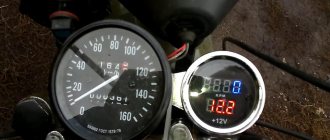
Unfortunately, many domestic and imported cars lack one very important device - a tachometer. Based on the diagram published in. The device has a two-digit digital indicator showing the number of thousands and hundreds of revolutions per minute. The electronic tachometer is powered from the vehicle's on-board network and consumes a current of 0.45A. The electrical circuit diagram of the device is shown in the figure.
The operation of the control unit is described in detail in. The input driver and counter are assembled according to a standard circuit and have no special features, so they immediately begin to work. An intermediate memory on triggers has been introduced into the digital tachometer circuit to eliminate flickering of the indicator numbers during counting. The operating cycle time is set by selecting resistor R11, and the measurement time by selecting resistor R7. For a conventional four-stroke, four-cylinder automobile engine, an inductive sensor is used.
It consists of 50...70 turns of PEL 1 wire. One end of the sensor coil must be insulated, and the other must be connected to the tachometer input. Thus, the value of the number of revolutions corresponds to the pulse frequency Hz. But since the tachometer indicator should show 3 at this time. Therefore, the measurement time in this case is set to 0.3 s. The operating cycle time should be 10...20 times greater than 3...6 s.
Construction and details. All microcircuits of the series can be replaced with the corresponding series. All parts of the electronic tachometer, except for R1 and the digital indicator, are placed on a double-sided printed circuit board measuring 60x mm. The board is placed in a polystyrene case measuring 65xx35mm. DA1 is installed on a small finned radiator. About 5 V drops across resistor R1, which significantly facilitates the thermal regime of the stabilizer.
If all parts are in working order, the device starts working immediately. The setup is as follows: a signal with a frequency of Hz is supplied to the base VT5, and the readings of indicator 3 are set by selecting R7.
In conclusion, I would like to note that according to this scheme, my friends have assembled several electronic tachometers, differing only in design, and all of them have been working perfectly for several years on various cars. Shirokov B. Digital tachometer. Biryukov S. Digital devices on integrated circuits. For sound and light effects, you can assemble a simple circuit using three transistors.
It can be used anywhere: on a car, on a motorcycle, on a scooter…. Like many music lovers, I had a desire to install a subwoofer in a car. But an ordinary box-shaped subwoofer occupied almost a quarter of Oda’s already small trunk. In addition, I had experience working with fiberglass. Yes, I live in Ukraine in a godforsaken muhosransk, where people drink, eat and smoke. It’s more than a km to the area, besides, it’s a peak or an atemega for me to find just a piece of cake, but you won’t find such a fossil even in garbage dumps!!!
Everything is relative, of course, but most of the parts, including microcircuits and indicators, are found in old Soviet color TVs. This circuit does not contain scarce parts such as programmable microcontrollers, microwave elements, etc. Subscribe to our RSS feed to receive site news. Stay connected! Master Vintik.
Everything with your own hands! Here you will find free reference books and programs. The site contains simple diagrams, as well as tips for DIY beginners. Some of the repair schemes and methods were developed by the authors and friends of the site. The rest of the material is taken from open sources and is used for informational purposes only. If you have a question about a pattern or craft?
We are always happy to provide assistance in setting up circuits, making repairs, and making crafts! Repair for beginners, useful tips and crafts, free diagrams, programs.
Radio element parameters. Digital tachometer from available parts Added by: Vintik ,Date: Oct 12 Category: . Tags: . You can follow comments on this entry via RSS 2. You can leave a comment:. Charger from a computer power supply. Car chargers. Principle of operation.
Expanding the capabilities of a computer mouse! Latest comments Vintik: Good afternoon. This means that not only the trance burned out. The problem seems to be in Vintik: Depends on the TV model. Need a diagram. Usually to the fee kin Vladimir: good afternoon
Vlad: Thank you for your advice and attention to my problem! Just p Screw: If there is mechanical damage, then check the connections carefully. Screw: I didn’t have such a malfunction. To find out the video path and Screw: You need to look at the signal from the receiver output with an oscilloscope and Screw: Is the plate spinning?
Tachometer for a diesel engine, operating principle, types of video
A fan with a heating function for a car for 600 rubles. Car cigarette lighter fan with heating function
Unlike other devices installed on cars, the tachometer for a diesel engine is connected through a generator. The device itself is designed to determine at what frequency the crankshaft rotates. In other words, the tachometer shows the number of revolutions over a certain period of time.
You can see the tachometer readings directly while driving; it is located near the speedometer on the instrument panel. Various types of sensors are used to take readings; depending on this, the measurement method can be non-contact or contact. Tachometers are used not only in cars, but also in other devices where control over rotation speed is required.
However, it is in cars that this device has found its widest application. Not a single modern car can do without this device, which allows you to control the operation of the engine and change gears in a timely manner. All this helps to increase service life, contributes to fuel economy, and ensures traffic safety.
There are many varieties of these devices that are used in certain cases.
The very first tachometer was a centrifugal one, where the energy coming from the mechanism is transmitted through an axle. The impact on the arrow in each case is carried out differently, depending on the design of the device.
Tachometer for a two-stroke engine - applications and selection
An electronic tachometer for a two-stroke engine should be considered separately.
One of the varieties of such a device is a waterproof version, used in motorcycles, scooters, snowmobiles and other vehicles with two-stroke engines.
In practice, this is the same as a tachometer for a single-cylinder engine, which determines its service life, as well as the frequency of maintenance, such as valve adjustment, oil change, spark plugs, etc.
Installing such a device on the mechanism is very simple. There is no need for a separate battery thanks to the built-in rechargeable battery. The connection is made directly to the wire of one of the spark plugs. The resolution of such a device is 0.1 hours, it can count up to a maximum of 10 thousand hours, and then reset.
Tachometer dials vary in size.
When a certain number of revolutions is reached, a special flash lamp is activated, after which the gear shifts into the next gear. Such large tachometers take up a lot of space and partially block the view.
Tachometer scale and its additional features
The design of each tachometer in a car provides for working with a specific number of cylinders. The bulk of these devices work with four-cylinder engines.
In some models it is possible to switch to the required number of cylinders.
Depending on the engine speed, the scale graduation has different meanings and can reach from 8 to 11 thousand revolutions per minute.
Certain types of tachometers equipped with a flash can remember the highest number of engine revolutions. The tachometer may additionally include other devices that display engine operation.
Such devices are called multidevices.
Chinese models
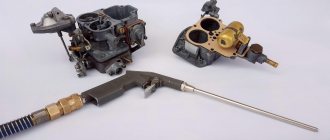
Adjusting the carburetor of a Chinese chainsaw, for example, Carver, is carried out in almost the same way as factory models. There are the same three main adjustment screws L, N, T. Sometimes such models have the ability to adjust the idle speed. But as a rule, employees of specialized services and owners of such saws claim that it is not always possible to set up a high-quality Chinese chainsaw right away.
For classic Chinese models, screw L should be loosened 1.5 turns from the maximum value. Screw H must be loosened one revolution from the maximum. Idle speed is adjusted in the same way.
The popularity of hand chainsaws is quite high, so they are used not only for work in the forest, but also in the household, for example, for pruning trees
They have many advantages, among which it is important to highlight mobility, reliability, and long service life. Although the last point depends not only on the quality of the tool, but also on the nature of its operation
The nature of operation includes not only compliance with the correct sawing technology, but also ensuring the care of the tool. In particular, starting to use a new chainsaw requires a break-in, after which you may need to adjust the carburetor. For such purposes, you will need a tachometer for a chainsaw.
What types of tachometers are there?
Car inverter 12 220v - how to choose a converter
Mostly there are analog (in the form of a dial with an arrow) and electronic (display) tachometers. More exotic ones - made in the form of a running scale on gas-discharge lamps (often found on American-made cars), as well as mechanical ones - a legacy of the very first cars.
Mechanical
The very first tachometers installed on cars in the early and mid-twentieth century were devices connected directly to the engine crankshaft.
The principle of operation was quite simple: there was a gear on the crankshaft that meshed with a cable drive, which transmitted torque to a coil, which was an electromagnet of the device itself. The more revolutions, the greater the magnetic induction that occurs, the more the needle of the device deviates. Everything is very simple. However, the measurement error was quite high and could reach values of up to 500 rpm.
Analog
Further development led to the emergence of analog tachometers using a similar operating principle. The difference is that instead of being constantly driven by the crankshaft, the frequency of power supplied to the ignition coil is used to read the number of revolutions.
What it looks like in action. To create a spark on the spark plug, a short-term low voltage pulse is applied to the coil that converts low (12V) voltage to high (from 12,000 to 24,000V). The same pulse is supplied simultaneously to the electrical circuit of the analog tachometer and the electromagnet winding. The more pulses are supplied to the winding, the greater the induction force appears, and the greater the angle the arrow deflects.
It should be noted that the error of analog tachometers can range from 100 to 500 rpm.
Digital
Since digital electronic tachometers are increasingly replacing their analog counterparts, not to mention mechanical ones, we will dwell on them in more detail.
The basic principle of operation of a digital tachometer is to measure and count the number of pulses arriving at the primary winding of the ignition coil, or measure the time interval corresponding to these intervals and convert the received information into digital values displayed on the display.
Video - digital tachometer with many settings and Shift Light:
In addition to the fact that a digital tachometer operates on all of the above values, to improve measurement accuracy, the device also processes values coming from the idle speed sensor and, sometimes, the crankshaft sensor. The 1xbet working website has a fairly wide line: there are about 35 different sports. The painting is also impressive, and, of course, the largest number of events is associated with football. However, for other directions there is plenty to choose from. You should also pay attention to eSports events, since this area is only gaining popularity: there are more and more games, as well as events related to them. Placing bets with 1xbet is not only fun and comfortable, but also as profitable as possible. All data is summed up, and the resulting average value is practically a true indicator.
Since approximately half of the total number of cars (especially compact or small cars) are not equipped with a standard tachometer, electronics manufacturers offer installation kits for self-installation of an electronic tachometer.
A simple set represents, in fact, the display itself, often liquid crystal with a built-in board for processing incoming information and a set of wires for connecting to the standard terminals of the coil (the first cylinder with a distributed ignition system), as well as power.
More complex ones may contain additional idle speed sensors, as well as an external optocoupler. However, such kits are installed for a specific purpose - to gain complete control over engine speed. A simple kit is sufficient for everyday use.
For clarity, below is a typical wiring diagram for an electronic tachometer that receives information only from the ignition coil.
As described above, the tachometer receives the signal from contact K of the ignition coil, which receives low voltage pulses, power is supplied from terminal B of the ignition coil (constant +12V when the ignition is turned on), minus is the vehicle’s weight.
Another version of the tachometer connection diagram - using information from the controller (the “brains”) of the car is shown below.
In this case, to display the number of engine revolutions, information received from the crankshaft position sensor and processed by the controller is used.
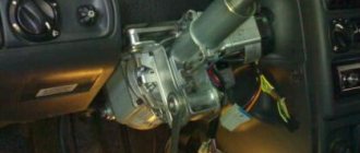
Technical solution
Before connecting the tachometer, it is necessary to draw up an electrical connection diagram in order to mentally determine the starting and ending switching points and trace the conductor. Any ignition coil has a terminal (terminal) +15 (ignition on), to which battery voltage is supplied when the key is turned to the first (for some cars, second) position. Under no circumstances should you connect the tachometer to this point; the first time you turn it on, it may fail. High-voltage wires also pose a danger, even to humans. The signal input to which the tachometer should be connected must be precisely determined. In older coils it is designated by the letter "K", it is better to find the exact circuit diagram of the car.
The next, more difficult task is the electrical connection of the nodes. As a conductor, you should take a stranded copper wire with a cross-section of at least 2 sq. mm. with polyvinyl chloride insulation.
The connection points of the wire to the ignition coil are cleaned, mechanically twisted, soldered and carefully insulated. Lay the wire along any electrical harnesses, using plastic clamps, towards the engine compartment bulkhead near the dashboard. You can insert the conductor into the passenger compartment next to any electrical wiring harness. To do this, it is easier to use an elastic string. Finally, connect the conductor to the tachometer signal terminal. In some cars that include modifications with or without a tachometer, you can simply change the dashboard, find the stock wire and connect it to the ignition coil.
Operating principle and types
The tachometer receives the signal from the pulse crankshaft speed sensor and converts them into the corresponding numerical value. When using various methods of calculating the control value (direct, reverse, mixed), the reading error reaches 100–500 rpm.
If we touch on the basic diagram of the devices, then in addition to the mechanical tachometer, which can already be considered a rarity, since it is found only on vintage cars, there are two more types of such devices:
- digital;
- analog.
You can also classify devices depending on the installation method:
- standard ones - as a rule, they are installed on the conveyor in a specially designated place on the dashboard of the car;
- remote – mounted outside the dashboard in addition to existing control devices, very often used on sports cars.
Digital tachometer
It is an electronic indicator (screen, display) showing the number of engine revolutions at a given time. It is believed that this representation is most convenient when working with electronic control units or when tuning (tuning) the motor. The device also includes a processor, an analogue to digital signal converter, an idle air valve sensor and another converter that is needed to transform electrical signals into light signals (optocoupler).
Analog tachometer
The appearance of such a device has already been described above. Visually, it is similar to most control and measuring instruments: there is a dial along which an arrow moves, indicating the number of revolutions. The value of the engine crankshaft rotation speed corresponds to the angle of rotation of the arrow relative to the zero value. One of the main elements of such a system is a magnetic coil that accumulates the energy necessary to turn the arrow. The electrical signal from the sensors is supplied through microcircuits to a coil that activates an arrow, which, by its deviation, indicates the value of the control parameter. Sometimes a combined design is used, when in addition to an analog device, a digital one is also installed. However, it is believed that with constant use, the signal from an analog tachometer is perceived by the human brain better than from a digital one.
Meter circuit
This meter is non-contact because it is enough to get close to, for example, a rotating motor shaft, on which there is a noticeable bright mark along the axis (a white line or white electrical tape), and after some time we get the numbers of pulses per second, and converting this into a revolution is already ordinary mathematics from elementary school. There is no conscious conversion done here so that you can measure the frequency of everything that emits light - monitors, LED displays, and so on.
This is the first mode, while the second is a simple counter of pulses (up to 65535) or objects moving in front of the counter. The modes change immediately after turning on the power when the number “1” is displayed. A long press of the button changes the mode to “2”. Holding it down again returns to “1”.
Tachometer with LCD display on microcontroller
There are two options - buy ready-made, or make it yourself. The second way will be within your power if you understand microcontroller technology and know how to program it. In other cases, it is better to purchase a finished product. Again, it should be noted that the VAZ 2101 wiring diagram will be slightly supplemented. First, you need to connect the tachometer to the positive terminal of the ignition switch. VAZ 2107 Replacing the heater radiator! In this video I will show you how to change the heater radiator on a VAZ 2107 car. Secondly, you will need to ensure that the pulses are read. This can be done in two ways:
- Take the signal from the ignition coil.
- Install the proximity sensor on the crankshaft.
The second solution will be more difficult, since you will have to upgrade the crankshaft pulley - you need to make a protrusion on it that will act on the contactless sensor. But taking the signal from the low-voltage output of the coil is a simpler solution.
Circuit diagram of a simple microcontroller tachometer
But you need to remember that during one revolution of the crankshaft exactly two flashes occur in the cylinders. Consequently, two signals will appear on the low-voltage terminal per revolution. This will need to be taken into account when making a tachometer for a VAZ 2101 with your own hands. VAZ 2105, VAZ 2106, VAZ and toe on the VAZ 2101 it is vertical as shown in. How to connect a 220 volt electric motor. In particular, at the stage of programming the microcontroller, this is necessarily taken into account in the algorithm. Which controller to choose is up to you. AtMega128, which has become a classic, will also do an excellent job. You can find a great variety of designs on it.
To control the actuator (in our case, an LCD display), it is advisable to use an amplifier - a Darlington assembly. How to connect the State on-board computer to a VAZ 2110. This is a small microcircuit that allows you to amplify the signal to the required value. Its price is insignificant, at least 10 rubles per piece, so there will be no problems with the purchase. With its help, the tachometer on the VAZ 2101 will be able to work as stably as possible, and there will be no chance that the output ports will be damaged. Be sure to connect the voltage divider to the input port. It will reduce the voltage coming from the ignition coil.
The module is powered from the ignition switch. How to replace the clutch cable on a VAZ 2109? The error when using microcontrollers can be either 3 revolutions per minute or 50. Therefore, study the datasheets and reviews of people who have used the devices for their designs. The photo shows an example of a circuit that can be used for a VAZ tachometer 2101
. It works stably, all that remains is to program it and install it in the dashboard of the penny. Due to its small dimensions, this will be much easier to do than in the case of installing a six indicator.
Video on installing a tachometer in a VAZ 2101:
Installation on a car with a carburetor
Before connecting the tachometer, it must be installed in the location chosen for it. This way you can immediately see how long of wire you will need. Then the negative cable is connected to ground. It is, as previously reported, black and white or completely charcoal.
Connect the brown or red wire to the ignition switch contact. Look at the diagram where the positive from the battery comes. If it is not there, then find it using a tester. This is done like this:
- set the multimeter to 20 V;
- Place the black probe on ground;
- Touch all the contacts in red one by one - the one you are looking for will have 12 volts.
The last posting is used to obtain data on the number of crankshaft revolutions 2105. Its color is not defined, each manufacturer uses its own. This cable in the contact ignition system goes to the distributor breaker. Otherwise, it is connected directly to the voltage switch. If the tachometer has its own backlight, then it is additionally connected to the car’s side lights circuit.
How to connect a car tachometer with your own hands
The main function of the tachometer in a car is to determine the correct gear, which has a positive effect on the life of the engine. Most cars have an analog tachometer built into them during assembly.
The driver looks at the arrow approaching the red line and knows when to shift into a higher gear.
Not all cars have the type of device that satisfies the owner, so you just need to figure out what they have and how to connect the tachometer.
Did you know? The term “tachometer” comes from the Greek τάχος - speed and μέτρον - measure.
Types of tachometers
There are two types of tachometers: digital and analog.
The first looks like a small screen on which the driver can see all the data he needs while driving.
The second one is simpler and looks like a board with arrows and values.
Remote
A remote tachometer is installed on the front panel of the car. For greater ease of placement, this device has a leg for mounting on the panel.
In addition, their stylish appearance gives the car elegance.
Staff
The standard tachometer is built into the dashboard of the car. This device is more convenient, since it is easier for the driver to perceive the movement of one arrow, rather than several indicators while driving. A standard tachometer is more often used in cars, and manufacturers of electronic devices produce kits for self-equipping cars.
Important! Measuring instruments are produced according to the car brand. Indications from a non-native mechanism will be incorrect
How to connect a tachometer through the computer If your car does not have a carburetor engine, and the injector, the tachometer is not connected to the ignition. In this case, you need to connect the engine control unit to the controller.
The connection diagram for the tachometer is simple: take the ground to the body (ground), connect the plus from the device to the ignition positive. The tachometer has two inputs: the first goes to the control unit, the second to the crankshaft position sensor.
The device connected to the computer will read pulses directly from the control unit controller.
Connection diagram for a tachometer on a gasoline engine
Secure the mechanism in its place (the location is determined by the type of device). Connect the black wire to the ground (body) of the car. Connect the red wire to the ignition switch terminal, which supplies 12 W during operation of the ignition system.
The third wire can be any color. Since the ignition system is contact and non-contact, we will consider where to connect the tachometer in both. With a contact system, the device is connected to the distributor breaker. In the second system - to the voltage switch.
If the car has a display backlight, the tachometer is connected to the terminal provided for this in the ignition switch.
How to connect a tachometer to a diesel engine
Since the process is labor-intensive, it must be carried out in an inspection pit. The first point of work is to dismantle the protective casing of the generator, try to avoid getting dirt. The second step is connecting the tachometer to the diesel generator. To do this, find the terminal marked “W” on the generator body and connect the device output to it.
Attention! It is imperative to close the contact coming from the oil pump. If this is not done, the tachometer may “lie”
It happens that the terminal indicated above cannot be found. In this case, disassemble the generator. Connect one of the wires connecting the winding and the rectifier to the tachometer cable. Insulate the wires and reassemble the generator in reverse order.
How to check the tachometer for functionality
We figured out how to connect a tachometer to a diesel and carburetor engine. Now let's look at the reasons for device breakdowns.
You notice problems in the operation of the measuring device, for example, an arrow jumping in different directions. There may be several reasons for the breakdown. If the engine runs for a long time, vibration will occur, which may damage the display.
The next reason may be oxidation of the contact group of the electrical wiring, damage to its insulation or disconnection from the tips. These are all visible causes that need to be eliminated immediately. If the sensor itself is broken, it needs replacement.
Interesting! The tachometer was designed by the American Curtis Widder in 1903.
Part selection rules
An important device for cars
You can install this unit yourself. To do this you will need the following tools and materials:
- screwdrivers,
- wiring diagram,
- keys,
- insulating tape,
- wires.
First you need to find out the operating principle of the unit in question. The pulses read by this device enter the ignition system coil, displaying information on the screen. Auto mechanics recommend buying an electronic tachometer.
When choosing this device, you should take into account the structural features of the VAZ 2105. Otherwise, the tachometer will show revolutions with a slight error. You can install a universal unit with switches. To do this, connect it to any type of engine.
In the selection process, you should also take into account the fact that there are dial and electronic tachometers. You can install a tachometer on a VAZ 2105 of the first type with a tuner. The second type includes the Balsat TX-319t model. It is a microprocessor device, the main task of which is to monitor the operation of the “five” engine. If necessary, the driver can select the most suitable mode. Before you figure out how to install a tachometer on a VAZ 2105, you need to take into account the capabilities of the car:
- measurement of crankshaft revolutions of 2-6 and 8-cylinder engines,
- availability of watches,
- ability to remember maximum and minimum temperatures,
- presence of a stopwatch,
- ability to measure crankshaft acceleration.
Installation of the device
How to connect a tachometer of this type is of interest to many VAZ 2105 car owners. First, select a mounting location. The negative wire is then connected to the vehicle body. The plus wire is connected to the corresponding ignition terminal. A voltage of 12 W appears in it.
The backlight allows you to see the speed at any time of the day, so auto mechanics recommend installing just such units. Before starting work, you need to figure out how to connect a tachometer of this type. For this, an appropriate scheme is used. The backlight wires are connected to the side marker switch. If the car is of an injection type, then the device is connected to the controller of the electronic engine control system. In this case, reading is performed from the last element. Installing a tachometer from another vehicle is prohibited, as difficulties may arise in the operation of the mounted unit.
A tachometer is a device for measuring the rotation speed of engines, shafts, and other mechanisms. The tachometer has been used in transportation technology for more than a hundred years. As a rule, it is installed on the dashboard. The device indicates the rotation speed of the internal combustion engine during operation. In modern cars equipped with electronic engine control systems, it is not always installed. However, the tachometer readings allow you to select the most suitable driving mode. In some cases, this allows you to save fuel or, conversely, switch to a more aggressive driving style. Therefore, experienced car enthusiasts and professional drivers often install dashboards with tachometers on their own.
Let's look at how to independently connect a tachometer.
Digital index
It's no secret that even expensive cars still use an analog tachometer, which is considered the most comfortable for the eye and the most common for quick reading.
How is this convenient? Firstly, this way you can catch a more suitable moment to change gears. Secondly, such a device is often used by fuel system tuners to achieve optimal engine operating conditions and mixture quality.
Obviously, such technology is more complex, and therefore its use on modern automotive technology is still very limited. The electronic device is based on a liquid crystal display, which is either included in the main analog tachometer or has its own place on the dashboard.
In addition to the display, there is a so-called analog-to-digital converter, which converts pulses from a magnetic coil into a digital signal in binary format. Typically this signal is sent to a digital processor. Its task is to analyze the received data and send it to the display in a form that will be understandable to the end user, the driver. Communication between the devices is carried out by an optocoupler, whose task is to diagnose the idle air valve to compare the received data with the reference data and adjust the output values.