What carburetors are installed on Oka cars?
To equip the power units of Oka cars, carburetors produced by the Dimitrovgrad Automotive Unit are used; DAAZ carburetors of a special series are produced.
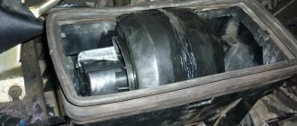
The DAAZ-1111 carburetor has some specific differences from similar devices . Thus, the float chamber of the mechanism is placed not along the carburetor, but across it. Thanks to this device, the carburetor mechanism can receive additional enrichment of the mixture immediately at the moment of sudden acceleration or braking.
Carburetor mechanism used to equip Oka cars
The DAAZ-1111 itself has a simplified design, as it contains a minimum number of electronic components. The main parts of the unit are:
engine starting device;
two internal combustion chambers;
float chamber and float.
All elements of the device are combined in a common housing cup. Protection from dirt, dust adhesion and unfavorable climatic conditions is provided by the housing cover.
For ease of operation and maintenance, the carburetor is divided into three parts:
The upper one, which consists of a cover with a flange, studs for fastening the air filter element and a fuel fitting.
The middle one is the carburetor body itself, which contains diffusers and a float chamber.
The lower one consists of throttle valves and drive rods.
The carburetor on the Oka performs its functions in exactly the same way as similar mechanisms installed on other vehicles. The fuel is supplied to the cavity of the float chamber, from where it is sent to the first or second chamber for air enrichment. Special sprayers crush gasoline droplets, so they easily mix with air and turn into an air-fuel mixture. This mixture enters the carburetor through diffusers and then into the engine.
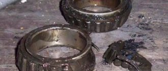
Device repair
Self-repair of a carburetor device requires a clear identification of the malfunction, the ability to properly dismantle the mechanism and wash it. In addition, in case of severe wear, it may be necessary to replace one or another structural element.
If the car owner does not have practical experience in servicing cars, it is not recommended to take any actions independently.
Video: performing repair work on the DAAZ-1111 with your own hands
Malfunctions and their diagnosis
The specificity of the structure of the cavities of the DAAZ-1111 carburetor is that exhaust gases are not removed immediately, but gradually. That is, the engine unit is forced to experience some difficulties when operating at high speeds. In addition, the entire design of the DAAZ-1111 does not prevent lubricating fluids from entering the carburetor, which can quickly lead to its contamination.
If the ignition system operates without interruption, the following malfunctions may occur on the Oka carburetor:
instability of the engine unit (this may be due to carbon deposits on the fuel nozzles or malfunctions of the economizer);
incorrect operation of the gas pedal while driving (the nozzle holes are clogged);
deterioration in the dynamic qualities of the car occurs due to a critical decrease in the fuel level in the float chamber - the engine simply does not have enough fuel to fully operate at high speeds;
jerks during movement indicate that carbon deposits have formed in the float chamber, therefore the normal movement of fuel in the system is disrupted;
instability of revolutions indicates that the carburetor trigger needs to be adjusted.
However, the main sign that indicates a malfunction of the carburetor can be considered a sharp increase in fuel consumption.
How to remove
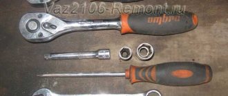
The removal procedure is quite simple, but it is recommended to follow a clear action plan so as not to damage the internal components of the carburetor during the dismantling process. To successfully carry out the work, you will need only three tools:
open-end wrench 8;
open-end wrench 13;
Before starting work, you must disconnect the wire from the negative terminal of the battery. This action will protect you from possible electric shock.
The procedure for dismantling the DAAZ-1111 carburetor is as follows:
It will be necessary to remove the air filter box. It is located in such a way that it prevents free access to the carburetor.
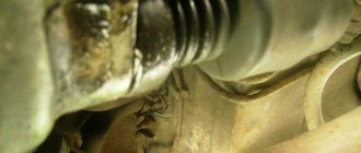
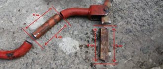
After this, you will need to loosen the bolted connection securing the damper drive rod to the lever. You will also have to slightly unscrew the bolt that secures the damper drive to the bracket.
After loosening, the bolts can be easily unscrewed - you need to disconnect the drive rod from all connections.
Using a screwdriver, disconnect the intermediate rod end from the lever.
Next, you need to disconnect the crankcase ventilation hose, which is connected to the fitting.
Afterwards, you can safely remove the wiring from the economizer valve.
The next step is to disconnect the vacuum regulator hose.
Next, you will need to loosen the clamp on the fuel supply pipe and remove the hose. Some fuel may spill out.
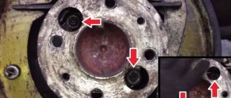
After which you can begin the procedure of removing the carburetor body. To do this, you will need to unscrew the forced idle economizer valve; behind them there are two nuts that need to be unscrewed.
After removing the filter element bracket, you can unscrew the two nuts that are located on the front side of the carburetor.
The device is carefully removed from the studs.
The main thing is to follow the exact procedure
Immediately after dismantling the carburetor, it is recommended to block the resulting hole in the intake manifold with a lint-free cloth. This measure is necessary to ensure that dust and dirt do not get inside.
Cleaning carburetor elements from carbon deposits and dirt
It is advisable to have the carburetor cleaned both outside and inside at a service station. However, if the car owner has experience in independently servicing his car, then it is allowed to clean the carburetor from carbon deposits with his own hands. However, you should be as careful as possible, since some parts of the mechanism require special care.
Do-it-yourself cleaning of the VAZ Oka carburetor
The most common problem with the failure of the normal operation of the Okushka engine is clogging of the carburetor unit, and both the jets and various channels can become clogged with debris and dirt. This raises all sorts of problems:
- idle speed disappears;
- The internal combustion engine does not develop speed;
- the motor is troublesome;
- fuel consumption increases;
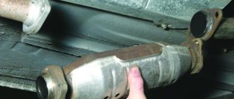
- Black smoke comes out of the muffler exhaust pipe.
In some cases, repairs as such are not required; you can only get by by cleaning the carburetor. One of the most common problems with VAZ small cars is clogging of the GDS channels, when the engine does not pick up speed when the damper of the first carburetor chamber is open, although the idle speed is not lost. Here, quite often it is possible to blow out the heat exchanger with compressed air on site, without removing the fuel mixing device itself. We perform this operation with our own hands approximately this way:
- with the engine turned off, open the hood, first of all dismantle the air filter housing (AHF);
- We use compressed air (using a hand pump, blower or compressor) to blow through the HDS channels;
- after such cleaning, we start the engine, check how the engine picks up speed;
If the operation of the internal combustion engine has returned to normal after the operation, you can replace the air filter; if not, repeat the purging again.
Installing a carburetor on the Oka
Reinstalling the carburetor mechanism on a vehicle after cleaning and repair can be a labor-intensive procedure. In order for the power unit to operate in normal mode, it is necessary to correctly connect all the components of the carburetor and securely fix them.
Getting started with installing the DAAZ-1111 is based on installing the gasket. The element is put on the studs and pressed tightly against the surface of the intake manifold. After which the carburetor itself is installed in its place:
First, screw in the two fastening nuts on the front side.
The other two nuts are tightened on the back side, after which the economizer valve can be returned to its previous position.
The first step is to connect the pipe that supplies fuel to the mechanism. It is recommended to use a new clamp to secure it.
Next, connect the vacuum regulator hose.
The connector that comes from the engine is connected to the forced idle economizer valve. Before connecting, it is advisable to make sure that the connector is clean and free of deformations.
The crankcase ventilation hose is connected to the fitting.
The tip of the intermediate rod of the lever is screwed to the corresponding place on the carburetor.
The drive rod is returned to its place and connected to the lines.
Next, it is recommended to install the air filter in place and check the operation of the system. If gasoline leaks out at the joints, you need to carefully tighten them again.
It is recommended to carry out all work in natural light or good artificial light
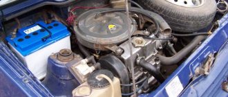
"Oka" 1111/11113 operating, maintenance and repair manual
VAZ-1111 Oka cars and their modifications are front-engine, with a transverse engine, front-wheel drive, four-seater. The body is two-volume, load-bearing structure, all-metal, welded. Engines - two-cylinder, in-line, four-stroke, carburetor, volume 0.65 l (currently not produced) and 0.75 l, power according to GOST 14846-81 (net) from 25.9 to 33.0 hp. Engines of the VAZ-1110 model were produced in a small batch. The cars were produced by the Kamsky (KAMAZ) and Serpukhov (SeAZ) automobile plants. Currently, the production of Oka cars remains only at the Serpukhov Automobile Plant, which also produces modifications for the disabled. The vehicle model and number, engine model and spare parts number are indicated on the nameplate attached to the upper cross member of the radiator frame. Ignition system Spark torque sensor: 1 - front roller bearing holder; 2 — sensor support plate; 3 — screen; 4 — spring weight of the centrifugal regulator; 5 — regulator weight, 6 — driving plate of the centrifugal regulator; 7- oil seal; 8 — roller; 9 — coupling; 10 — bushing of the rear end of the roller; 11 — driven plate of the centrifugal regulator; 12 — vacuum regulator; 13 — fitting for supplying vacuum; 14 - thrust; 15 — contactless sensor (Hall sensor); 16 — body; 17 — Hall sensor wiring block; 18 - cover; a - diagram of the operation of the centrifugal regulator; ἁ — ignition timing angle. Details of the spark torque sensor: 1 - coupling; 2 - body; 3 — vacuum ignition timing regulator; 4 - oil seal; 5 - non-contact sensor (Hall sensor); 6 — driving plate of the centrifugal regulator; 7 — weight of the centrifugal regulator; 8 — drive plate roller; 9 - spring; 10 — driven plate of the centrifugal regulator with a screen; 11 — lock washer; 12 — sensor support plate with bearing; 13 — bearing lock plate; 14 — front bearing holder; 15 - cover. The ignition system is contactless. Consists of a spark torque sensor, switch, ignition coil, spark plugs, ignition switch and high and low voltage wires. Spark timing sensor - type 5520.3706 (until 1989, a type 55.3706 sensor was installed) with built-in vacuum and centrifugal ignition timing regulators. It sets the moment of spark formation depending on its initial setting, the number of revolutions of the crankshaft and the load on the engine. Reading of control pulses is based on the Hall effect. There is one pulse for each revolution of the crankshaft (two for each revolution of the camshaft). The initial ignition timing angle for the VAZ-1111 engine is 1±1° before TDC, for the VAZ-11113 it is 4±1° before TDC. You can check the functionality of the Hall sensor with a voltmeter by connecting it between the terminals of the green and white-black wires. Slowly rotating the spark sensor shaft, we monitor the voltmeter readings. The voltage should change sharply from the minimum (no more than 0.4 V) to the maximum (no more than 3 V less than the supply voltage). If a steel screen with slots touches the sensor (determined by slight jamming or a scratching sound when the roller rotates, as well as after partial disassembly of the spark torque sensor), check the axial play of the roller (no more than 0.35 mm, adjusted by selecting washers) and the fit of the screen on roller If necessary, replace the assembly. A faulty Hall sensor cannot be repaired and must be replaced with a new one (with the exception of a broken wire between the sensor itself and the block on the spark torque sensor housing). You can roughly assess the serviceability of the vacuum regulator directly on the car. With the engine running, disconnect the vacuum hose leading to the regulator from the carburetor fitting. If you now create a vacuum in the hose (you can use your mouth), the engine speed should increase, and when the vacuum is removed, it should decrease again. The vacuum should remain for at least a few seconds if the hose is pinched. You can visually verify the functionality of the vacuum regulator by partially disassembling the spark torque sensor (see “Removing and disassembling the spark torque sensor,” p. 86) and applying a vacuum to the inlet fitting of the regulator. In this case, the screen of the spark torque sensor should rotate at an angle of 10±1°, and when the vacuum is removed, return back without jamming. Accurate testing and adjustment of vacuum and centrifugal ignition timing regulators is carried out on special stands. It is not recommended to do this at home. If the vacuum regulator fails, it is replaced; if the centrifugal regulator fails, the spark torque sensor is replaced.
A switch type 3620.3734, or 36.3734, or HIM-52 opens the power supply circuit of the primary winding of the ignition coil, converting the sensor control pulses into current pulses in the ignition coil. The switch is checked with an oscilloscope using a special method; if a malfunction is suspected (interruptions in engine operation, shots in the muffler), replace it with a known good one. Do not disconnect the switch connector while the ignition is on - this may damage it (as well as other components of the ignition system). Ignition coil - two-output, dry, type 29.3705 - with an open magnetic circuit, or type 3012.3705 - with a closed magnetic circuit. Data for testing: resistance of the primary winding at 25 ° C - (0.5 ± 0.05) Ohm, secondary - (11 ± 1.5) kOhm. The insulation resistance to ground is at least 50 MOhm. Spark plugs - type A17DVR, or A17DVRM, or their imported analogues (with noise suppression resistors with a resistance of 4-10 kOhm). The gap between the electrodes should be within 0.7-0.8 mm (checked with a round wire probe).
High-voltage wires - type PVVP-8 with distributed resistance (2000±200) Ohm/m or PVPPV-40 with distributed resistance (2550±270) Ohm/m. Do not touch high-voltage wires while the engine is running - this may result in electrical injury. It is also prohibited to start the engine or allow it to operate with an open high-voltage circuit (removed wires) - this can lead to insulation burnout and failure of the electronic components of the ignition system. Ignition switch type 2108-3704005-40 or KZ813 with anti-theft locking device, blocking against restarting the starter without first turning off the ignition. When the key is turned to the “ignition” position, voltage is applied to the control input of an additional relay type 113.3747-10, which, in turn, supplies voltage to the ignition coil and switch. Thus, the contacts of the ignition switch are relieved (see also “Electrical equipment”). Diagram of a non-contact ignition system: 1 - ignition switch relay; 2 — ignition switch; 3 - fuse block; 4 - switch; 5—sparking moment sensor; 6 — ignition coil; 7 - spark plugs.
A book in a series of full-color illustrated guides to do-it-yourself car repairs. The manual describes the design features of components and systems of Oka VAZ-1111, -11113 vehicles, as well as their modifications for disabled drivers. The main malfunctions, their causes and solutions are described in detail. The disassembly and repair processes are illustrated and annotated. A separate section is devoted to car care. The Appendices present tools, lubricants and operating fluids, lip seals, bearings, tightening torques for threaded connections, as well as a diagram of electrical equipment. The book is intended for drivers who want to repair a car themselves, as well as for service station workers.