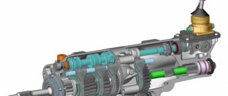
Planetary gear is a type of gear used in manual and automatic transmissions. In addition to converting rotation, the planetary gear is capable of summing and distributing power. Knowing about the planetary mechanism: what it is, how it works, by what criteria the gearbox is evaluated, the structure and characteristics of the automatic transmission will become clear. In the event of a breakdown, calculating the transmission will help you choose a reliable and durable mechanism.
Design and principle of operation
A planetary mechanism is a structure of gears moving relative to the center. Wheels of different diameters are located along the central axis:
- small solar with external teeth;
- large crown or epicycle with internal teeth.
The satellites move between the wheels. Their rotation resembles the movement of the planets of the solar system. The mechanical axes of the satellites are connected to a carrier, which rotates about the central axis.
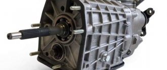
Construction of a simple planetary block:
- 1 epicycle;
- 1 sun wheel;
- 1 carrier.
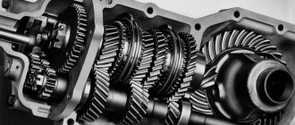
The planetary mechanism is assembled in cascades of two or more links on one shaft to obtain a wide range of gears. The main kinematic characteristic of a gear transmission is the gear ratio.
The operating principle of the planetary gearbox is to lock one of the main elements and transmit rotation through the drive wheel. To stop the element, brake bands, locking clutches, and bevel gears are used. The gear ratio varies depending on the fastening scheme. It is more convenient to describe the operating principle of a planetary mechanism using an example:
- The crown is blocked.
- The shaft supplies torque to the sun.
- The rotation of the sun causes the planets to roll around with it.
- The carrier becomes a slave, indicating a lower gear.
By controlling the elements of a simple “planetary”, you get different characteristics:
| Broadcast | How does a planetary gearbox work in an automatic transmission? |
| 1 | The sun sends rotation to the carrier, the crown moves in the opposite direction. |
| 2 | The crown applies rotation to the carrier, the sun is fixed. |
| 3 | The leading carrier transmits rotation to the sun. The crown is blocked. |
| 4 | The carrier moves the crown. The sun is fixed. |
| Reverse | The carrier is blocked. The solar wheel rotates, the planets roll around and move the corona in the opposite direction. |
The efficiency η of a simple transmission reaches 0.97.
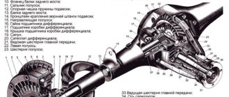
A planetary gear set with one degree of freedom becomes a planetary gear. Two degrees form a differential. The differential adds up the torques on the driven wheel coming from the main drive links.
Read
How to drift automatically
Types of planetary gears
Based on the number of stages, planetary mechanisms are divided into:
- single row;
- multi-row.
The planetary gear consisting of one sun gear, single-rimmed satellites, carrier and epicycle will be single-row. Replacing satellites with double-crown ones complicates the design, making it double-row.
The multi-stage planetary gearbox is a series of single-row units. This scheme allows you to sum up the gear ratios and get larger values. 4-speed automatic transmissions consist of two-row planetary designs, 8-speed automatic transmissions consist of four-row ones.
Automatic transmissions use circuits named after the inventors:
- The Wilson mechanism is a three-row design in which the crown of the first, carrier of the second and crown of the third rows are connected. Number of gears: 5 direct and 1 reverse.
- The Lepeletier mechanism consists of 3 coaxially located simple planetary gears. Number of gears: 6 direct and 1 reverse.
- Simpson's scheme - 2 gearboxes with a common sun gear. The second row carrier is equipped with a brake. The crown of the first row and the sun are rigidly connected to the drive shaft through two locking couplings. The mechanism implements the following modes: neutral; 1,2,3 gears; reverse.
According to the type of gear structures, planetary gearboxes are divided into:
- cylindrical;
- conical;
- wave;
- worm-type
Different types are used to transmit torque between shafts located parallel or at an angle. And also in mechanisms requiring low or high kinematic characteristics.
Configuration options
In a planetary mechanism, wheels (gears) of various configurations can be used. Standard ones with straight teeth, helical, worm, and chevron teeth are suitable. The type of gearing will not affect the general operating principle of the planetary mechanism. The main thing is that the rotation axes of the carrier and the central wheels coincide. But the axes of the satellites can be located in other planes (crossing, parallel, intersecting). An example of a crossed differential is a cross-axle differential, in which the gears have a conical shape. An example of crossed ones is a self-locking differential with a worm gear (Torsen).
Characteristics of the main varieties of this device
Various types of gears are used in the design of the planetary gear set of automatic transmissions. There are three main most common ones: cylindrical, conical and wave.
Cylindrical
Gear mechanisms transmit torque between parallel shafts. The design of a cylindrical gear includes two or more pairs of wheels. The shape of the gear teeth can be straight, oblique or chevron. The cylindrical circuit is simple to manufacture and operate. Used in gearboxes, final drives, drives. The gear ratio is limited by the size of the mechanism: for one wheel pair it reaches 12. Efficiency is 95%.
Read
Automatic transmission cooling system and installation of an additional universal radiator
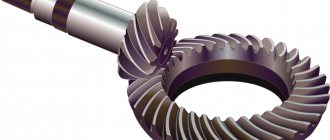
Conical
Wheels in a conical design convert and transmit rotation between shafts located at an angle of 90 to 170 degrees. The teeth are loaded unevenly, which reduces their ultimate torque and strength. The presence of forces on the axes complicates the design of the supports. For smooth connection and greater endurance, a circular tooth shape is used.
The production of bevel gears requires high precision and is therefore expensive. Angular structures are used in gearboxes, valves, and milling machines. The gear ratio of bevel mechanisms for medium-duty equipment does not exceed 7. Efficiency is 98%.
Wave
In wave transmission there are no sun and planetary gears. Inside the crown wheel there is a flexible oval-shaped gear. The carrier acts as a wave generator, and looks like an oval cam on a special bearing.
A flexible steel or plastic wheel is deformed under the action of the carrier. Along the major geometric axis, the teeth engage with the crown to the entire working height; along the minor axis there is no engagement. The movement is transmitted by a wave created by a flexible gear wheel.
In wave mechanisms, the efficiency increases along with the gear ratio exceeding 300. Wave transmission does not work in circuits with a kinematic characteristic below 20. The gearbox produces 85% efficiency, the multiplier - 65%. The design is used in industrial robots, manipulators, aviation and space technology.
Story
The process of the industrial revolution was marked by the transition of wooden parts to metal ones. Wind- and water-powered propulsors already created forces that were difficult for wooden parts to withstand. The main factor of the industrial revolution was the creation of more advanced mechanisms and the search for new energy resources. The advent of the steam engine required very large capacities. Consequently, there was a need to design metal gearboxes. By the mid-nineteenth century, handlooms had already begun to fade into the background and be replaced by mechanical ones with three times the productivity.
Energy became cheaper, which led to increased speed of machine tools and strengthened their economic advantage. The steam engine was powerful enough to run several textile machines. The machines were placed around the steam engine to increase efficiency. The steam engine freed up production capabilities, which made it possible to build enterprises both near water and in places where there was coal, transport, labor and markets. New times have selected optimal gear designs.
It was those that had the highest economic effect that gained the most popularity. The mid-19th century was marked by the appearance of the first serial gearboxes. Well, the appearance a few years later of internal combustion engines and electric drives marked the creation of gearboxes with specified parameters. Gear mechanisms transmitted rotational movements from high-speed engines and transformed their parameters. Even the earliest examples of electric motors and internal combustion were endowed with too much speed and torque, which, a priori, was not suitable for use in industry. Today, of course, it is difficult to find any vehicle or technological equipment that is devoid of a gear mechanism. Gearboxes are used in almost all vehicles and technological equipment. As you already understand, gear drives have gone through many years of development.
Advantages and disadvantages of planetary gears
Planetary gears outperform simple gear mechanisms of similar power due to their compact size and 2-3 times less weight. Using several planetary gears, 80% tooth engagement is achieved. The load capacity of the mechanism increases, and the pressure on each tooth decreases.
The kinematic characteristic of the planetary mechanism reaches 1000 with a small number of gears without the use of multi-row structures. In addition to the transmission, the planetary circuit is capable of operating as a differential.
Due to the alignment of the shafts of the planetary mechanism, it is easier to assemble machines than with other gearboxes.
The use of a planetary gear set in an automatic transmission reduces the noise level in the vehicle interior. A balanced system has high vibration resistance due to vibration damping. Accordingly, body vibration is reduced.
Disadvantages of the planetary mechanism:
- complex production and high precision assembly;
- bearings are installed in the satellites, which fail faster than the gear;
- As the gear ratio increases, the efficiency drops, so the design has to be complicated.
Read
Shifting the automatic transmission gear selector on the go
Planetary gear ratio
The gear ratio is the ratio of the frequency of the drive shaft of a planetary gear to the frequency of the driven one. It is not possible to determine its value visually. The mechanism is driven in different ways, which means the gear ratio is different in each case.
To calculate the gear ratio of a planetary gearbox, the number of teeth and the fastening system are taken into account. Let's say the sun gear has 24 teeth, the pinion has 12, and the crown has 48. The carrier is fixed. The sun becomes the leader.
The satellites will begin to rotate at the speed transmitted by the sun gear. The gear ratio is: -24/12 or -2. The result means that the planets rotate in the opposite direction from the sun with an angular velocity of 2 revolutions. The satellites roll around the crown and force it to turn 12/48 or ¼ of a turn. Internal wheels rotate in the same direction, so the number is positive.
The total gear ratio is equal to the ratio of the number of teeth of the drive wheel to the number of teeth of the driven wheel: -24/48 or -1/2 of a revolution is made by the crown relative to the sun with the carrier fixed.
If the carrier becomes driven with the leading sun, then the gear ratio is: (1+48/24) or 3. This is the largest number that the system can offer. The smallest ratio is obtained when the crown is fixed and torque is applied to the carrier: (1+/(1+48/24)) or 1/3.
Gear ratios of a simple planetary scheme: 1.25 - 8, multi-stage: 30 - 1000. As the kinematic characteristics increase, the efficiency decreases.
INTRODUCTION
Calculation and graphic work is carried out in A1 format in accordance with the requirements of GOST 2.109-73 “Basic requirements for drawings”. On the left side of the format, a diagram of a planetary gearbox is drawn (Fig. 2) in two projections. The right side of the format shows the gearing on the selected scale (Fig. 3). We choose the scale of construction in such a way that the height of the tooth in the drawing is at least 40 mm
. It is mandatory to construct three teeth of the 1st and 2nd wheels.
The final stage of the calculation and graphic work is the execution of the calculation and explanatory note (see clause 4).
Selection of numbers of teeth of planetary gears
The number of wheel teeth is selected at the first stage of calculating the planetary scheme according to a predetermined gear ratio. The peculiarity of designing a planetary gear set is to comply with the requirements of proper assembly, alignment and proximity of the mechanism:
- the teeth of the satellites must coincide with the depressions of the sun and the epicycle;
- The planets should not touch each other with their teeth. In practice, more than 6 satellites are not used due to difficulties in uniformly distributing the load;
- The axles of the carrier, sun and crown wheels must coincide.
The basic ratio for selecting transmission teeth through the gear ratio looks like this:
i = 1+Zcorona/Zsun,
where i is the gear ratio;
Read
Reliability of the Skoda Rapid automatic and the transmission used
Zn is the number of teeth.
The coaxial condition is observed when the interaxial distances of the sun wheel, crown and carrier are equal. For a simple planetary gear train, the center distances between the central wheels and satellites are checked. Equality must satisfy the formula:
Zcorona=Zsun+2×Zsatellite.
In order for there to be a gap between the planets, the sum of the radii of adjacent gears should not exceed the axial distance between them. The condition of proximity to the sun wheel is checked using the formula:
sin (π/c)> (Zsatellite+2)/(Zsun+Zsatellite),
where c is the number of satellites.
Planetary wheels are placed evenly if the ratio of crown and sun teeth to the number of satellites is integer:
Zsun/s = Z;
Zcorona/s = Z,
where Z is an integer.
Strength calculation of planetary gears
Strength calculations of planetary gears are carried out as for cylindrical gears. Calculate each link:
- external - between the sun and planetary wheels;
- internal - between the planets and the crown.
If the wheels are made of the same material, and the meshing forces are equal, the least strong connection is calculated - the external one.
The calculation algorithm is as follows:
- Select a gearbox circuit.
- The initial data is determined: gear ratio i, torque Tout and output shaft speed Uout.
- The number of teeth is selected by checking the assembly conditions and the proximity of the planetary gears.
- The angular speeds of the wheels are calculated.
- Calculate the efficiency and moments of the output shafts.
- Calculate the adhesion strength.
When calculating the moment, the number of planetary wheels and the uneven loading of their teeth are taken into account. Enter a correction factor η =1.5...2 if there are no leveling measures:
- increased manufacturing accuracy;
- radial mobility of the sun, corona or carrier;
- use of elastic elements.
The calculation of gears is carried out according to two criteria:
- contact strength, i.e. endurance of working surfaces of teeth under load;
- bending stress, fatigue fracture.
Calculation of contact strength comes down to checking the condition that the stress σн does not exceed the permissible value. Calculations are carried out using the Hertz formula for cylindrical surfaces, adding clarifying coefficients. As a result, the value of the center distance is obtained - the main geometric characteristic of the gear drive:
d=K×η×∛ (T×Kн(i±1))/(Ψ×i×[σн]^2),
where K is the auxiliary coefficient for spur gears, MPa;
η—unevenness coefficient;
T — torque, N×mm;
Kn - load factor;
Read
Which gearbox is better, automatic or manual: pros and cons
Ψ — wheel width coefficient equal to 0.75;
i—gear ratio;
[σн] - permissible contact stress, MPa. Determined by the durability coefficient and endurance limit.
After determining the transmission geometry, the strength condition is checked:
σн= {310/(d×i)}×√ (T×Kн(i+1)^3)/(Ψ×d) ≤ [σн]
When calculating bending, the condition is assumed that the entire load is transferred to one pair of teeth and applied to its top. The design voltage should not exceed the permissible:
σf= (M/W) – (F/(b×s) ≤ [σf],
where M is the bending moment;
W is the axial moment of resistance;
F—compression force;
b, s - dimensions of the tooth in section;
[σf] is the permissible bending stress. Depends on the endurance limit, roughness, and manufacturing errors of the teeth.
Tips for selecting a planetary gearbox
Before choosing a planetary gearbox, an accurate calculation of the load and operating modes of the mechanism is carried out. Determine the type of transmission, axial loads, temperature range and standard sizes of the gearbox. For heavy special equipment that requires high torque at low speeds, a gearbox with a high gear ratio is chosen.
To reduce the angular speed without reducing the torque, a drive with an electric motor and gearbox is used. When choosing a gear motor, consider:
- operational load;
- output shaft torque;
- rotation speed of input and output shafts;
- electric motor power;
- installation execution.
Tags
Planetary gearbox Types of planetary gearboxes, operation of a planetary gearbox, planetary type gears. Planetary orTypes of planetary gearboxescomplexities of planetary gearbox.therefore, planetary gearbox with planetary gearboxwith planetary gearplanetary gearbox of planetary gearboxes of planetary gearbox provides the gearbox cup to the gearbox cover.planetary gearboxes reduction gearboxes.planetary gearbox.differential gearbox receivedplanetary gearbox received
masterslave
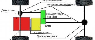
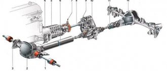
Application area of planetary gears
The planetary diagram is used in:
- gearboxes;
- automatic and manual transmissions;
- in aircraft drives;
- differentials of cars, devices;
- driving axles of heavy equipment;
- kinematic diagrams of metal-cutting machines.
A planetary gearbox is used in units with variable gear ratios, braking the carrier. In tracked vehicles, the elements in the planetary mechanism do not block for the addition of power flows.
How many satellites should there be?
Compared to a conventional gear, there are more teeth in the planetary gear, and all of them are involved in moving power. With an increase in the number of satellites, the load on each of them decreases; accordingly, it is possible to reduce their diameter and width (material intensity of production) while maintaining the strength characteristics of the planetary gearbox device. Power dissipation is accompanied by reduced tooth wear, as well as increased torsional rigidity of the drive.
Planetary gearboxes usually use three (less often, four) satellites. As their number increases, the requirements for precision in the execution of parts also increase. Thus, the displacement of one of the satellite axes leads to an uneven distribution of transmitted power. This negatively affects the service life of teeth and bearings.