The main signs of a malfunction of the mass air flow sensor (another name is a flow meter, mass air flow sensor, MAF-sensor) - increased fuel consumption, interruptions in engine operation (loss of power, floating speed, stalls at idle, hard to start when cold) and other similar symptoms of a malfunction Therefore, this sensor is also checked in parallel.
To find out exactly what the reason is, a comprehensive diagnosis of the car is carried out using a scanner (tester) or a random check of sensors, including a flow meter, a multimeter (voltmeter) and other methods. We will discuss these and other points further.
What is he responsible for?
The MAF sensor plays an important role in forming the correct air-fuel mixture. The sensor constantly monitors the volume of air passing through the intake system and transmits the received data to the ECU.
The latter, having received information from the flow meter and other sensors, forms a fuel-air mixture that guarantees engine operation at optimal speeds with minimal fuel consumption.
Other sensors can also correct the MAF readings: atmospheric pressure and air temperature, but they are not installed on all cars.
If the MAF sensor is broken, then the volume of incoming air is determined by the controller based on the angle of the throttle valve. This does not ensure economical operation of the engine, but the car drives.
Why do you need an air flow sensor (MAF) in a car?
To meet environmental and economic requirements, the electronic engine control system (ECM) must know how much air is drawn into the cylinders by the pistons during the current operating cycle. The calculated amount of time for which the gasoline injection nozzle will be open in each of the cylinders depends on this.
Since the pressure drop across the injector and its performance are known, this time is clearly related to the mass of fuel received for combustion during one engine operating cycle.
Indirectly, the amount of air can also be calculated by knowing the crankshaft rotation speed, engine displacement and throttle opening degree. This data is hardwired into the control program or provided by the corresponding sensors, so the engine continues to operate in most cases when the mass air flow sensor fails.
But determining the air mass per cycle will be much more accurate if you use a special sensor. The difference in operation is immediately noticeable if you remove the electrical connector from it. All the symptoms of MAF failure and the disadvantages of working with the bypass program will appear.
Types and principle of operation of flow meters
The mass air flow sensor is a hot-wire device.
The main types that are used on cars:
- Film with analog and digital signal.
- Wire (thread) analog.
- Frequency mass air flow sensor. Already installed on most modern cars coming off the assembly line.
Pitot tube (vane type) flowmeters are not considered due to their outdated design.
The operating principle of the first two types of devices is similar to each other and is based on changing the voltage readings supplied to the heating elements (threads or film). The ECU monitors these changes and performs calculations to form the fuel-air mixture. More details below.
Wire mass air flow sensor
Used on most modern cars. In such devices, the key role is played by thermistors - two tungsten or platinum filaments with a diameter of 0.07 mm, to which voltage is applied with a certain current strength, as a result they heat up, as well as a thermistor (temperature sensor), but it is not provided everywhere.
One thread is closed from the air flow, and the second, with the throttle valve open, on the contrary, is blown and actively cooled.
To equalize the temperature readings of thermistors, more current is supplied to the open thread.
The ECU takes into account the difference in voltage readings between the threads, the intensity of their cooling and, based on them, calculates the volume of incoming air and, in accordance with this, calculates the required amount of fuel supplied to the cylinders.
Wire mass air flow sensors have several significant disadvantages: over time they become dirty or wear out.
To solve the first problem, the designers developed a self-cleaning mode. It provides for short-term (so as not to discharge the battery) heating of the filament to 1000-11000C with the engine turned off. At this temperature, all deposits burn out.
When the thermistors wear out, the sensor is replaced.
Film flowmeters
Structurally, such sensors differ from the first ones, although the principle of their operation is largely the same.
Instead of a sensitive thread thermistor, a platinum-coated ceramic heating element or semiconductor film is installed here.
The location of the film device remains the same, and the ceramic element itself has several resistor layers, each of which performs its own function: a temperature sensor, a heating one, two thermistors.
An important advantage of such a sensor is that it measures the temperature of not only the incoming air, but also the reflecting air. The device is also less susceptible to contamination.
It is worth noting that in modern devices, the output signal U is transmitted not only in analog mode, but also in digital mode, this speeds up data processing.
Frequency mass air flow sensor
The General Motors product was installed on the first VAZ 2109 and worked in tandem with the January 4 ECU. It is characterized by reliability and a long service life.
The principle of operation is not based on a change in direct voltage, but on a change in the frequency of the output signal of an alternating signal U. When the frequency is high, this indicates high air flow, low frequency indicates low air flow.
The main advantage of a frequency flow meter is stable data transmission to the ECU when the voltage in the circuit drops (poor contact, oxidation, etc.).
Let's imagine that the contacts in the connectors have oxidized. Then the output signal of 1.02V will decrease and, for example, 0.9V will come to the controller. This is not critical, but it will increase fuel consumption.
In the frequency sensor, voltage surges do not affect the operation of the ECU in any way. Oxidation of the contacts will not change the signal frequency in any way, which means 100% of the output data will reach the recipient, i.e. controller (ECU).
How does Nissan DMRV work?
On Nissans, the air flow sensor is located behind the filter, before the throttle valve. At the inlet, the air flow is uniformly distributed using a honeycomb grid.
The sensitive element of the device is a plate or wire that is heated to a certain temperature under the influence of an electric current flowing through it. When the air flow cools it, the power (and therefore the voltage and strength) of the current increases to heat the element to its original temperature. Moreover, the more intense the air flow (and therefore the larger its volume), the more it cools the element, and the more significant the changes in the parameters of the electric current.
A stoichiometric or normal mixture has a proportion of 14.7/1 air and fuel. The flow meter does not measure the amount of oxygen (or any other chemical element), but the magnitude of the indicators (voltage, force and power) of the electric current required to warm the cooled sensitive element of the sensor. The pistons draw the air flow into the cylinders, and the air temperature sensor (ATS) records its temperature. This is a semiconductor resistor, where there is a sharp dependence of electrical resistance on air temperature (the lower t, the higher the resistance, and therefore the voltage in the DTV).
Its malfunction has little effect on the operating parameters of the engine, however, it significantly increases fuel consumption. By the way, if you notice such a change and difficulty accelerating movement, then first of all check the serviceability of the air flow sensor. On Nissans, this will be accompanied by the inclusion of “CHECK ENGINE” on the instrument panel, since the ECU will record and save the error code. If the error is not corrected, the engine will receive an excessively enriched fuel mixture, which will significantly increase gasoline consumption.
So, the power parameters of the electric current become a measure of the mass of the flowing air flow. This value is converted into an analog or digital signal and sent to the ECU.
Based on the received signals, it sets the exact time interval for the open position of the dampers, thereby regulating the volume of fuel supplied to the mixture with the optimal composition. In addition, the control unit adjusts temperature and speed parameters, torque and other indicators, optimizing the operation of the motor.
What does the malfunction lead to?
It cannot be said that a breakdown of the flow meter will immediately lead to critical consequences, but if you ignore the problem, then prolonged operation of the engine on an incorrectly formed air-fuel mixture will lead to rapid wear of the elements of the cylinder-piston group, and when several factors overlap, detonation in the engine and even its “wedge” can occur. .
For example, if a rich mixture enters the engine, the engine will quickly overheat as a result of oil dilution.
Also, a faulty MAF sensor, due to deterioration in exhaust purity, significantly affects the reduction of the service life of the catalytic converter, particulate filter and exhaust system as a whole.
Signs of malfunction of the DMVR
As is already clear from the above material, if the mass air flow sensor is faulty, the ECU forms a fuel-air mixture without maintaining the correct proportion.
For example, you need 1:14, and the mixture will enter the cylinders in a ratio of 1:15 (lean) or 1:13 (rich). And at a ratio of 1:5 the mixture does not ignite at all.
As a result, a breakdown of the flow meter may manifest itself with the following symptoms:
- Difficulty starting the engine (especially in cold weather).
- Increased fuel consumption.
- Floating speed at idle, the car stalls. At the same time, this may not happen on a cold engine, but as soon as the engine warms up, the speed jumps from 1000 to 1600 per minute.
- The engine does not pull, acceleration dynamics have disappeared.
- The car drives jerkily.
- The car stalls when upshifting or downshifting.
- The "Check Engine" light comes on and does not go out.
- Rapid overheating of the motor.
It is important to understand that all these signs do not specifically indicate a malfunction of the MAF sensor and here you need to take a comprehensive approach to finding the causes of the failure and use different diagnostic methods.
Causes of failure
Here we list the main reasons why the mass air flow sensor fails or does not work correctly:
- Burnout (burst) of the thermistor or damage to the coating on the tracks. This disease is especially typical for the HFM-5 sensor model. This can happen as a result of natural wear and tear or a sudden surge in voltage in the network (the generator has failed, etc.). On average, wire devices last about 150 thousand car miles.
- Lack of voltage – break in the signal or operating electrical circuit, the sensor is not connected, oxidation of the contacts.
- The ECU has failed.
- Incorrect maintenance. The flow meter is considered a maintenance-free device and can be replaced as an assembly. But since it is expensive, many try to clean it, for example, with cotton wool, which is wrong. To do this, use compressed air or special liquids (carbocleaner, special air flow sensor cleaner or other alcohol-based product).
Indirect reasons:
- The throttle valve is jammed as a result of its contamination - in this case, the sensor seems to be working, but the information is not transmitted to the ECU correctly.
- The air filter is clogged.
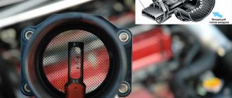
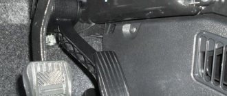
MAF sensor location
Locate the MAF between the air filter box and the throttle body. On some models, the sensor is located inside the air filter housing.
If you need help finding a meter, get a vehicle repair manual for your specific make and model of car.
| Index |
| 1. Quick MAF Diagnostic Procedure Without DMM |
| 2. How to check |
| Power check |
| Voltage Signal Testing |
| Frequency Signal Testing |
| Hot Wire Testing |
| 3. I replaced the faulty MAF sensor, but I see no improvement |
| 4. What if my sensor is faulty? |
Locate the MAF sensor in the air filter assembly.
How to quickly determine that the sensor is faulty?
To quickly check the mass air flow sensor for functionality, do the following:
- Start the car and warm up the engine to operating temperature (up to 80 degrees is possible). To speed up the process, increase the speed periodically.
- Turn off the car.
- Disconnect the terminal from the sensor.
- Start again without pressing the gas pedal.
- If the engine begins to sharply gain speed, which is not typical for idling, then, on the contrary, goes to the bottom, then the air flow meter is faulty.
How to check frequency-type air flow sensor
Let's look at the example of Citroen Peugeot 1.6 HDI diesel. A similar four-wire MAF sensor is found on the models shown below.
To check, you will need a diagnostic scanner or multimeter that supports this function.
Sensor pinout:
- Intake temperature sensor output signal.
- Weight.
- Not involved.
- On-board voltage +12V.
- Frequency signal from the sensor.
Connect:
- Second Pin – “ground”
- The fifth Pin is the output signal.
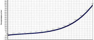
At rest with the ignition on, the output frequency should be 5 kHz.
After starting the engine at idle, the frequency should decrease and vary from 1.02 to 3.3 kHz. For each frequency mass air flow sensor frequency table.
How to check the mass air flow sensor
Generally, there are three types of MAFs that have been used for many years: low frequency, DC voltage and high frequency type.
For example, GM used a low frequency type MAF meter in 1988 and older models. He then switched to high frequency sensors starting in 1989. Most new vehicle models also use high frequency sensors.
While doing these tests, try to check for a voltage signal, if you know your MAF sensor is a high frequency type (newer car model), you can use a voltmeter that can measure frequency. If you have an older model car with a low frequency type MAF, you can use a digital multimeter that can measure the car's speed (tachometer, rpm). If necessary, consult your vehicle's repair manual.
If possible, start the engine and let it idle for about 15 minutes to warm up. Then turn off the engine and continue with the following tests.
Features of testing for Ford Focus 2
In most cases, for foreign cars, the flow meter diagnostic methods are similar, but they still have their own characteristics. It all depends on the car model and the brand of the installed MAF sensor.
For example, on Ford Focus 2 there are sensors with four or six wires. Original product FORD 1072308.
The pinout is shown below using an example of a 4-wire sensor.
- A – voltage 12V.
- B – “–” (mass).
- C – “–” reverse earth (literal translation).
- D – output signal SIG to the ECU.
Two additional wires are connected to the 6-pin sensors: IAT (intake air temperature) sensors.
To check the mass air flow sensor on a Ford Focus 2, do the following:
- Disconnect the connector from the flow meter.
- Turn on the ignition.
- Connect the “–” of the multimeter to “B” (ground) on the wiring harness (see the figure above).
- “+” of the device to positive “A” (12V).
The multimeter should show 12V. If not, then we look for the reason why the sensor does not receive U.
Next steps (you will need an assistant):
- Plug the chip back in.
- Without turning off the ignition, using sharp multimeter probes, connect “+” (pierce the wire) to the signal “D”, and “–” to “C” (reverse ground). The norm is 0.9 – 1.0V.
- Ask an assistant to start the car, warm it up and set the speed to 1500. The device should show 1.4 - 1.6V. At 2500 rpm – 1.8 – 2.0V.
- With the gas pedal fully depressed (as the speed increases), the device should show from 0.2 to 5V.
The range of standard indicators is not indicated by chance. It will vary depending on engine size.
Also diagnose Ford Focus 2 with a scanner (read above). The standard air flow rate is 9–12 kg/h or about 2.8 g/s at idle speed.
Types of mass air flow sensors
Although there are two common types of MAF, hot wire and hot film, the most common types are hot wire. Test procedures for troubleshooting hot wire sensors may vary depending on the make of vehicle. You can further categorize MAF sensors into low frequency, voltage and high frequency types.
Some car models use a MAF that sends a voltage signal to the computer. But later models may use a voltage frequency signal.
Nissan Almera
Nissan Almera is equipped with mass air flow sensors from Hitachi, although you can also find products from Bosch. And you need to understand that the readings on devices from different manufacturers will differ.
To understand the process, we will make replacements on the Hitachi flow meter. Read above for the example of Bosch.
There are 5 wires going to the sensor. Measurements are taken first with the ignition on, then with the engine running. Prepare the multimeter by switching it to 20V mode.
Procedure:
- Insert a needle or pin into the third wire (pierce the insulation) on the air filter side.
- Turn on the ignition. “–” of the multimeter for battery ground, “+” for the needle. The norm is no more than 0.4V.
- Start the car and follow the steps in step 2. The norm is no more than 1.04V. Up to 1.05V is still respectable.
Diagnostics of mass air flow sensor
If there is no similar sensor, then there are other ways to check the performance of the flow meter:
- visual diagnostics;
- checking while driving;
- determining firmware compliance;
- diagnostics with a tester.
Visual inspection
Before checking the device using this method, it must be removed from its mounting location. To do this, the pipes are disconnected from the housing of the air filter element. The inside of the controller must be dry; traces of motor fluid and condensation are not allowed. Often the device breaks down due to non-compliance with the air filter replacement intervals, as a result of which dirt remains on the sensitive component. This leads to the controller giving incorrect readings.
If there are traces of motor fluid on the internal cavity of the controller, this indicates a high level of lubricant pressure in the power unit. The reason may be a clogged crankcase ventilation. When checking, you need to make sure that the sealing element is located in the right place where the corrugation is installed. This part may have become stuck in the air filter housing. With this problem, air leaks into the engine, which gets inside with dust and contaminates the regulator.
Diagnostics on the move
It is necessary to disconnect the plug with the power circuit from the sensor and start the engine, and then disconnect the block. The Check Engine indicator will appear on the dashboard. The minimum engine speed should increase to 1500 per minute. If the engine begins to operate more stably after turning off the device, this indicates a malfunction. The sensor needs to be replaced.
User Igor Belov spoke about several methods for diagnosing the flow meter, including checking while driving.
Compliance of the mass flow sensor with the ECU firmware
To check the firmware compliance, you need to take a 1 mm thick plate and place it under the damper stop, this will lead to a change in engine speed. Then the block with wires is disconnected from the controller. If the car engine does not stop, then the reason is the firmware of the microprocessor module, idle speed controller without a flow meter in emergency mode.
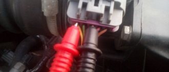
Checking the mass air flow sensor with a multimeter
For diagnostics, the ignition is activated, but the power unit does not need to be started. Use the contact of the red probe on the tester to touch the first cable (yellow), and the black one goes to ground (green contact). It is not recommended to use sharp objects for connection, as this will lead to errors in the readings. This diagnostic method will allow you to determine the voltage level between the conductors.
The status of the sensor will be determined by the following readings:
- from 0.99 to 1.01 V - parameters of the new controller;
- 1.01 - 1.02 V - the regulator is in excellent condition, no need to change;
- 1.02 - 1.03 V - generally satisfactory condition of the device;
- 1.03 - 1.04 V - the controller’s service life is almost exhausted, replacement will soon be required;
- 1.04 - 1.05 V - the sensor is in unsatisfactory condition, it’s time to change the device.
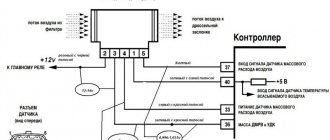
Diagnostics by the tester may not be performed on all types of flow meters. The pre-diagnostic mode of the multimeter must be configured to measure the value of direct current and set the maximum parameter to 2 V. Four cables are connected to the controller, each of which is designated by a specific color.
Starting from the near conductor to the windshield:
- the yellow contact is intended for input of a flow meter pulse;
- a white or gray cable is used as the supply voltage output channel;
- green contact is ground or ground;
- The black cable, equipped with a pink stripe, is responsible for the output to the main relay.
The colors of the contacts on the mass air flow sensor may be different, but the arrangement of the wires is always identical.
The “Simple Opinion” channel talked about performing diagnostics on a flow meter using a tester.
Flushing the sensor
Flushing the mass fuel flow sensor is a slippery topic. This helped some, while others, on the contrary, remained stuck with the “broken trough” - the flow meter completely failed.
The process itself is not complicated, disassemble (if the design allows) and clean the threads or film. If it is not possible to disassemble, use compressed air.
To wash the air flow sensor, special alcohol-based products are used.
Carburetor cleaners, solvents, and gasoline are used at your own risk. For some, the problem was solved, for others, the platinum coating was washed off.
Do not saw the product point-blank, but from a distance of 5–10 cm.
What to do if the MAF signal level is low?
When this problem occurs, diagnostics is performed:
- the presence or absence of supply voltage, as well as the reliability of connecting the device to ground;
- resistance level between contact element 5 (in the diagram) of the connector and ground, this indicator should be from 4 to 6 kOhm.
The problem may be:
- poor quality contact;
- incorrect wiring harness route;
- wear or damage to the cable core or insulating layer;
- poor connection of the device to ground;
- connecting more powerful energy consumers to the block.
Device diagnostics includes the following steps:
- The quality of contact between pins 7 and 12 on the injection system connector, as well as the sensor, is checked. A visual check of the condition of the block is performed to ensure correct connection. The problem may be damage to the locks or the use of damaged contact elements. The connection quality of the conductor to the block may be poor.
- You need to make sure that the harness route is not broken. Problems may arise if the cable harness is laid close to high-voltage wires.
- The integrity of the harness is checked to ensure that it is not damaged. If the element is visually intact, you need to try to move it and at the same time monitor the readings of the diagnostic equipment.
- The air filter device is also checked for clogging. If required, it is replaced.
If you have a tester, you can check the serviceability of the mass air flow sensor as follows:
- The key is turned in the lock to turn off the ignition. It is necessary to disconnect the connector with wires from the controller.
- Then the ignition is turned on, but the power unit does not start.
- The tester is used to diagnose the voltage level between the contact elements on the connector. Between outputs 2 and 3 this value should be above 10 volts, between 3 and 4 - 5 V, and between ground and the third contact - 0 V. If the values obtained are different, it is necessary to eliminate breaks in the line and get rid of the short to ground.
- Then the ignition in the car is turned off. Using a multimeter, you can diagnose the resistance level between the fifth contact and the ground on the block.
Connection diagram of the flow meter to the microprocessor
If the resulting value is about 4.6 kOhm, then the regulator itself is faulty. The problem may lie in its poor-quality connection. If the resistance level is 0 ohms, the problem is a short to ground of the fourth contact or a malfunction of the sensor. If the obtained value is more than 100 kOhm, this indicates a break in the 4G wire or a breakdown of the regulator.
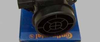
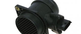
Purchasing a new and replacing the mass air flow sensor
Purchasing and replacing a mass air flow sensor is not a problem. The market is teeming with offers. Prices also vary from 2500 to 9000 rubles. For VAZ and GAZ, look for Bosch products with article number 0280218037.
To replace you will need:
- Cross-shaped or flat decoction.
- Key head 10 (for Lada Kalina).
Procedure:
- Loosen the air duct clamp bolt and move the latter to the side.
- Press the button under the plug and pull the latter out of the connector.
- Using a 10mm wrench, unscrew the two bolts (one on top, the other on bottom).
- Remove the sensor.
- Installation in reverse order.
1 of 3
— +
1.
2.
3.
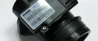
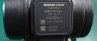
Before buying a new flow meter, pay attention to the markings of the old one. It is advisable to purchase a product with the same marking so that it is guaranteed to be compatible with the car’s ECU.
The main thing after replacement is not to forget to adapt the new flow meter. To do this, remove the negative terminal of the battery for a few minutes to expose the data in the ECU.
In some car models, this cannot be done in a garage; you will have to go to a service center where there is special diagnostic equipment.
Recommendations for increasing service life
To extend the life of the MAF sensor, follow these recommendations:
- Change the air filter promptly to minimize clogging of the flow meter.
- Monitor the technical condition of the engine, carry out maintenance on time, change and fill only with high-quality engine oil.
- If the car has a high mileage, check the engine compression - wear or jamming of the piston rings and valve seals will lead to oil penetration into the intake system. This will prevent the appearance of oil deposits on the thermistors.
- Monitor the condition of the crankcase ventilation system. This is especially true for those engines where the crankcase gas suction pipe is connected in front of the mass air flow sensor. Check the condition of the oil separator under the valve cover.
How to clean the sensor yourself?
By cleaning and flushing the air flow controller, you can restore its operation.
In particular, you will have to work with the sensitive element of the sensor - this part always becomes dirty during operation of the flow meter.
Selecting a cleaner
To complete the task you need to purchase a cleaning agent:
- Liquid Moly. This brand's mass air flow sensor cleaner is not cheap. But its use allows you to effectively remove contaminants and restore the operation of the device. The use of Liqui Moly cleaning products can be carried out on mass air flow sensors running on gasoline or diesel internal combustion engines.
- Technical or medical alcohol. This option is one of the oldest and most effective. The chemical properties of alcohol allow you to efficiently remove dirt from the sensitive part of the sensor.
- Carburetor engine cleaner. One of the most inexpensive and effective ways to restore the controller.
- Liquid key product. Allowed for use not only on mass air flow sensors, but also for cleaning other components and mechanisms.
- WD-40. Allows you to remove not only dirt, but also traces of rust.
Step-by-step instruction
Do-it-yourself repair of the mass air flow sensor is carried out as follows:
- Before removing the sensor, turn off the ignition and disconnect the terminal from the battery. In the engine compartment, the connector is removed from the flow meter.
- A pipe is connected to the device; it is also loosened and disconnected. Using a wrench, you unscrew the bolt that secures the mechanism to the air filter, in particular, to its body.
- The device is removed from the corrugation. Depending on the car model, this may require different tools, including star keys. The screws securing the device are unscrewed, and then the flow meter is removed from the landing site.
- If there are traces of oil on the device, they must be removed. To clean, use one of the products described above.
- The sensors themselves on the flow meter are usually made in the form of a wire located on a mesh. When using a cleaner, you must carefully treat the sensitive component. The film must not be damaged. When the area of contamination is cleaned, you need to wait about 10 minutes for the product to take effect.
- If there is too much dirt on the device, then it is advisable to repeat the cleaning procedure several times. To ensure rapid evaporation of the product, you can use a compressor or pump. But too high a pressure can destroy the sensing element of the flow meter.
Photo gallery
Dismantling the flow meter
Cleaning with WD-40