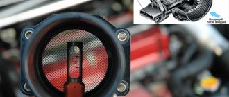
The main signs of a malfunction of the mass air flow sensor (another name is a flow meter, mass air flow sensor, MAF-sensor) - increased fuel consumption, interruptions in engine operation (loss of power, floating speed, stalls at idle, hard to start when cold) and other similar symptoms of a malfunction Therefore, this sensor is also checked in parallel.
To find out exactly what the reason is, a comprehensive diagnosis of the car is carried out using a scanner (tester) or a random check of sensors, including a flow meter, a multimeter (voltmeter) and other methods. We will discuss these and other points further.
What is he responsible for?
The MAF sensor plays an important role in forming the correct air-fuel mixture. The sensor constantly monitors the volume of air passing through the intake system and transmits the received data to the ECU.
The latter, having received information from the flow meter and other sensors, forms a fuel-air mixture that guarantees engine operation at optimal speeds with minimal fuel consumption.
Other sensors can also correct the MAF readings: atmospheric pressure and air temperature, but they are not installed on all cars.
If the MAF sensor is broken, then the volume of incoming air is determined by the controller based on the angle of the throttle valve. This does not ensure economical operation of the engine, but the car drives.
What is a flow meter
As stated above, flow meters are designed to indicate the volume and regulate the air consumed by the engine. Before moving on to a description of the principle of their operation, it is necessary to touch upon the issue of types. After all, his work will depend on this.
Types of flow meters
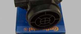
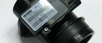
Flow meter appearance
The very first models were mechanical and were installed on the following fuel injection systems:
- Jetronic distributed injection;
- combined electronic injection and electronic ignition system Motronic;
- K-Jetronic;
- KE-Jetronic;
- L-Jetronic.
The body of a mechanical flow meter contains a damping chamber, a measuring valve, a return spring, a damping valve, a potentiometer, and a bypass (bypass) with an adjustable regulator.
In addition to mechanical flow meters, there are also the following types of more advanced devices:
- heated filament flow meter;
- flow meter with film hot-wire anemometer;
- flow meter with thick-walled diaphragm;
- manifold air pressure sensor.
Next, let's look at the operating principle of the listed devices.
Operating principle of the flow meter
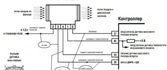
Mechanical flow meter diagram. 1 – voltage supply from the electronic control unit; 2 – incoming air temperature sensor; 3 – air supply from the air filter; 4 – spiral spring; 5 – damping chamber; 6 – damping chamber damper; 7 – air supply to the throttle valve; 8 – air pressure damper; 9 – bypass channel; 10 – potentiometer
Let's start with a mechanical flow meter . Its operating principle is based on how much the measuring damper will move depending on the volume of air it passes through. On the same axis as the measuring damper there is also a damping damper and a potentiometer (adjustable voltage divider). The latter is made in the form of an electronic circuit with soldered resistor tracks. In the process of turning the damper, the slider moves along them, and thus the resistance changes. Accordingly, the voltage transmitted by the potentiometer is measured in accordance with positive feedback and transmitted to the electronic control unit. To adjust the operation of the potentiometer, an intake air temperature sensor is also included in its circuit.
However, mechanical flowmeters are now considered obsolete as they have been replaced by their electronic counterparts. They do not have moving mechanical parts, therefore they are more reliable, give a more accurate result, and their operation does not depend on the temperature of the intake air.
Another name for such flow meters is mass air flow sensor . In turn, they are divided into two types depending on the sensing element used:
- wire (Hot Wire MAF Sensor);
- film (Hot Film Air Flow Sensor, HFM).
MAF (mass air flow sensor)
More details
Air flow meter with wire heating element (filament). 1 – temperature sensor; 2 – sensor ring with a wire heating element; 3 – precision rheostat; Qm – mass air flow per unit time
The operation of devices of the first type is based on the use of a heated platinum filament . The electrical circuit constantly maintains the thread in a heated state (platinum was chosen due to the fact that the metal has low resistivity, does not oxidize and is not susceptible to aggressive chemical factors). The design provides that the passing air cools its surface. The electrical circuit has negative feedback, whereby as the filament cools, more electrical current is supplied to it in order to maintain the temperature at a constant level.
The circuit also contains a converter, whose task is to convert the value of the changing current into a potential difference, that is, voltage. There is a nonlinear exponential relationship between the obtained voltage value and the volume of air passed through. The exact formula is programmed into the ECU, and in accordance with it, it decides how much air is needed at a given time.
The design of the wire flow meter implies a so-called self-cleaning mode. In this case, the platinum thread is heated to a temperature of +1000°C. As a result of heating, various chemical elements, including dust, evaporate from its surface. However, as a result of such heating, the thickness of the thread gradually decreases. This leads, firstly, to errors in the sensor readings, and secondly, to gradual wear of the thread itself.
Diagram of a mass air flow meter with a film hot-wire anemometer. 1 - electrical connector leads, 2 - measuring pipe or air filter housing, 3 - computing circuit (hybrid circuit), 4 - air inlet, 5 - sensor sensing element, 6 - air outlet, 7 - bypass channel, 8 - sensor housing.
Now let's look at the operation of the film mass air flow sensor . They come in two types - with a film hot-wire anemometer and based on a thick-walled diaphragm. Let's start the description with the first one.
It is the result of the evolution of the wire flowmeter, but instead of wire, in this case a silicon crystal is used as a sensing element, onto the surface of which several layers of platinum are soldered, used as resistors. In particular:
- heating resistor;
- two thermal resistors;
- intake air temperature sensor resistor.
By analogy with a wire flow meter, the sensing element is located in a channel through which air passes. It is in a constantly heated state thanks to the use of a heating resistor.
When air enters the channel, it changes its temperature, which is recorded using thermistors installed at both ends of the channel. The difference in their readings at the two ends of the diaphragm is a potential difference, that is, a constant voltage (ranging from 0 to 5 V). Most often, this analog signal is digitized in the form of electrical impulses that are transmitted directly to the vehicle's ECU.
As for the second type of film flowmeter, they are based on the use of a thick-walled diaphragm located on a ceramic base.
The principle of measuring air mass flow with a film hot-wire anemometer. 1 – temperature characteristic in the absence of air flow 2 – temperature characteristic in the presence of air flow; 3 – sensitive element of the sensor; 4 – heating zone; 5 – sensor diaphragm; 6 – sensor with measuring pipe; 7 – air flow; M1, M2 – measurement points, T1, T2 – temperature values at measurement points M1 and M2; ΔT – temperature difference
Its active sensor detects changes in air vacuum in the intake manifold based on the deformation of the film diaphragm. With significant deformation, a corresponding dome with a diameter of 3...5 mm and a height of about 100 microns is obtained. Inside there are piezoelectric elements that convert mechanical effects into electrical signals, which are subsequently transmitted to the ECU.
Modern cars that use electronic ignition use air pressure sensors , which are considered more technologically advanced than classic flow meters operating according to the schemes described above. The sensor is located in the manifold and determines the pressure and load of the engine, as well as the amount of gases recirculated. In particular, it is connected to the intake manifold using a vacuum hose. During operation, a vacuum occurs in the collector, which acts on the sensor membrane. Directly on the membrane there are strain gauges, whose electrical resistance changes depending on the position of the membrane.
The sensor's operating algorithm consists of comparing atmospheric pressure and pressure on the membrane. The larger it is, the greater the change in resistance, and therefore the voltage supplied to the ECU. The sensor's power supply is 5 V DC, and the control signal is a pulse with a constant voltage from 1 to 4.5 V (in the first case, this is engine idling, in the second, engine operation at maximum load). The ECU directly calculates the mass amount of air, also based on the density of the air, its temperature, as well as the number of revolutions of the crankshaft.
Due to the fact that the mass air flow sensor is a rather vulnerable device and often fails, since approximately the beginning of the 2000s, automakers began to abandon its use in favor of using engines with an air pressure sensor.
Film air flow meter. 1 – measuring circuit; 2 – diaphragm; 3 – reference pressure chamber; 4 – measuring elements; 5 – ceramic substrate
Using the received data, the electronic control unit adjusts the following parameters. For gasoline engines:
- fuel injection timing;
- its quantity;
- moment of ignition initiation;
- algorithm of operation of the gasoline vapor recovery system.
For diesels:
- fuel injection timing;
- algorithm of operation of the exhaust gas recirculation system.
As you can see, the sensor design is simple, but it performs a number of key functions, without which the operation of internal combustion engines would be impossible. Now let's move on to considering the signs and causes of malfunctions of this unit.
Types and principle of operation of flow meters
The mass air flow sensor is a hot-wire device.
The main types that are used on cars:
- Film with analog and digital signal.
- Wire (thread) analog.
- Frequency mass air flow sensor. Already installed on most modern cars coming off the assembly line.
Pitot tube (vane type) flowmeters are not considered due to their outdated design.
The operating principle of the first two types of devices is similar to each other and is based on changing the voltage readings supplied to the heating elements (threads or film). The ECU monitors these changes and performs calculations to form the fuel-air mixture. More details below.
Wire mass air flow sensor
Used on most modern cars. In such devices, the key role is played by thermistors - two tungsten or platinum filaments with a diameter of 0.07 mm, to which voltage is applied with a certain current strength, as a result they heat up, as well as a thermistor (temperature sensor), but it is not provided everywhere.
One thread is closed from the air flow, and the second, with the throttle valve open, on the contrary, is blown and actively cooled.
To equalize the temperature readings of thermistors, more current is supplied to the open thread.
The ECU takes into account the difference in voltage readings between the threads, the intensity of their cooling and, based on them, calculates the volume of incoming air and, in accordance with this, calculates the required amount of fuel supplied to the cylinders.
Wire mass air flow sensors have several significant disadvantages: over time they become dirty or wear out.
To solve the first problem, the designers developed a self-cleaning mode. It provides for short-term (so as not to discharge the battery) heating of the filament to 1000-11000C with the engine turned off. At this temperature, all deposits burn out.
When the thermistors wear out, the sensor is replaced.
Film flowmeters
Structurally, such sensors differ from the first ones, although the principle of their operation is largely the same.
Instead of a sensitive thread thermistor, a platinum-coated ceramic heating element or semiconductor film is installed here.
The location of the film device remains the same, and the ceramic element itself has several resistor layers, each of which performs its own function: a temperature sensor, a heating one, two thermistors.
An important advantage of such a sensor is that it measures the temperature of not only the incoming air, but also the reflecting air. The device is also less susceptible to contamination.
It is worth noting that in modern devices, the output signal U is transmitted not only in analog mode, but also in digital mode, this speeds up data processing.
Frequency mass air flow sensor
The General Motors product was installed on the first VAZ 2109 and worked in tandem with the January 4 ECU. It is characterized by reliability and a long service life.
The principle of operation is not based on a change in direct voltage, but on a change in the frequency of the output signal of an alternating signal U. When the frequency is high, this indicates high air flow, low frequency indicates low air flow.
The main advantage of a frequency flow meter is stable data transmission to the ECU when the voltage in the circuit drops (poor contact, oxidation, etc.).
Let's imagine that the contacts in the connectors have oxidized. Then the output signal of 1.02V will decrease and, for example, 0.9V will come to the controller. This is not critical, but it will increase fuel consumption.
In the frequency sensor, voltage surges do not affect the operation of the ECU in any way. Oxidation of the contacts will not change the signal frequency in any way, which means 100% of the output data will reach the recipient, i.e. controller (ECU).
Functionality check
Before diagnosing the mass air flow sensor, you need to know the symptoms that allow you to determine the degree of performance of the MAF (abbreviation for the English name of the device) sensor in the car. We list the main symptoms of a malfunction:
- The consumption of the fuel mixture has increased significantly, while at the same time acceleration has slowed down.
- The internal combustion engine idles with jerks. In this case, a decrease or increase in speed may be observed in idle mode.
- The engine does not start. Actually, this reason in itself does not mean that the flow meter in the car is faulty; there may be other reasons.
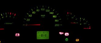
- A message appears about a problem with the engine (Cheeck Engine)
An example of the displayed message “Cheeck Engine” (marked in green)
These signs indicate a possible malfunction of the mass air flow sensor; in order to accurately determine the cause of the failure, it is necessary to perform diagnostics. It's easy to do it yourself. Connecting a diagnostic adapter to the ECU (if this option is possible) will help to significantly simplify the task, and then determine the serviceability or malfunction of the sensor using the error code. For example, error p0100 indicates a fault in the flow meter circuit.
Finding an error using a diagnostic adapter
But if you need to carry out diagnostics on domestic cars manufactured 10 years ago or more, then checking the mass air flow sensor can be carried out in one of the following ways:
- Testing while moving.
- Diagnostics using a multimeter or tester.
- External inspection of the sensor.
- Installation of a similar, known-good device.
Let's consider each of the listed methods.
Testing while driving
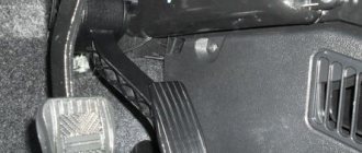
The easiest way to check is by analyzing the behavior of the internal combustion engine with the MAF sensor disabled. The algorithm of actions is as follows:
- You need to open the hood, turn off the flow meter, close the hood.
- We start the car, and the internal combustion engine goes into emergency mode. Accordingly, a message indicating a problem with the engine will appear on the dashboard (see Fig. 10). The amount of fuel mixture supplied will depend on the position of the remote control.
- Check the dynamics of the car and compare it with what it was before the sensor was turned off. If the car has become more dynamic and power has also increased, then this most likely indicates that the mass air flow sensor is faulty.
Note that you can continue driving with the device turned off, but this is highly not recommended. Firstly, the consumption of the fuel mixture increases, and secondly, the lack of control over the oxygen regulator leads to increased pollution.
Diagnostics using a multimeter or tester
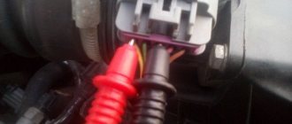
Signs of a malfunction of the mass air flow sensor can be identified by connecting the black probe to ground, and the red probe to the sensor signal input (the pinout can be found in the device data sheet, the main parameters are also indicated there).
An example of measuring the voltage on the mass air flow sensor in a VAZ 2114 car with a multimeter
Next, we set the measurement limits to 2.0 V, turn on the ignition and take measurements. If the device does not display anything, you need to check that the probes are connected correctly to ground and the flow meter signal. Based on the readings of the device, you can judge the general condition of the device:
- A voltage of 0.99-1.01 V indicates that the sensor is new and working properly.
- 1.01-1.02 V - used device, but its condition is good.
- 1.02-1.03 V - indicates that the device is still operational.
- 1.03 -1.04 the condition is approaching critical, that is, in the near future it is necessary to replace the mass air flow sensor with a new sensor.
- 1.04-1.05 – the device’s resources are almost exhausted.
- Over 1.05 - a new mass air flow sensor is definitely needed.
That is, you can correctly judge the state of the sensor by the voltage; a low signal level indicates an operational state.
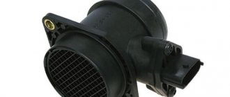
External inspection of the sensor
This diagnostic method is no less effective than the previous ones. All that is necessary is to remove the sensor and assess its condition.
Inspect the sensor for damage and fluid
Characteristic signs of a malfunction are mechanical damage and liquid in the device. The latter indicates that the oil supply system to the engine is not adjusted. If the sensor is very dirty, the air filter should be replaced or cleaned.
Installing a similar, known-good device
This method almost always gives a clear answer to the question of the sensor’s performance. This method is quite difficult to implement in practice without purchasing a new device.
What does the malfunction lead to?
It cannot be said that a breakdown of the flow meter will immediately lead to critical consequences, but if you ignore the problem, then prolonged operation of the engine on an incorrectly formed air-fuel mixture will lead to rapid wear of the elements of the cylinder-piston group, and when several factors overlap, detonation in the engine and even its “wedge” can occur. .
For example, if a rich mixture enters the engine, the engine will quickly overheat as a result of oil dilution.
Also, a faulty MAF sensor, due to deterioration in exhaust purity, significantly affects the reduction of the service life of the catalytic converter, particulate filter and exhaust system as a whole.
Diagnostics with a tester
The second method involves using a multimeter. Before you start testing, you must remember that the method is not relevant for all sensors. This method can only check the Bosch air flow meter.
The first step is to set the tester to 2 V and switch it to constant voltage mode. The Bosch diagram clearly states that the mass air flow sensor must have four wires. So, a signal is sent through the yellow wire, the gray-white wire is voltage, the green wire is ground, the pink-black wire is powered along with the main relay.
Now the red tester probe must be connected to the yellow wire. The black probe connects to the green wire. Before these measurements, the engine must be turned off, but the ignition does not need to be turned off. Next, the voltage is measured.
If the element is in working condition, the tester will show 101-102. Acceptable readings are 102-103. This is the upper limit at which air flow meter repair is required. If the tester screen shows 105 or more, then the sensor is broken and requires replacement.
Signs of malfunction of the DMVR
As is already clear from the above material, if the mass air flow sensor is faulty, the ECU forms a fuel-air mixture without maintaining the correct proportion.
For example, you need 1:14, and the mixture will enter the cylinders in a ratio of 1:15 (lean) or 1:13 (rich). And at a ratio of 1:5 the mixture does not ignite at all.
As a result, a breakdown of the flow meter may manifest itself with the following symptoms:
- Difficulty starting the engine (especially in cold weather).
- Increased fuel consumption.
- Floating speed at idle, the car stalls. At the same time, this may not happen on a cold engine, but as soon as the engine warms up, the speed jumps from 1000 to 1600 per minute.
- The engine does not pull, acceleration dynamics have disappeared.
- The car drives jerkily.
- The car stalls when upshifting or downshifting.
- The "Check Engine" light comes on and does not go out.
- Rapid overheating of the motor.
It is important to understand that all these signs do not specifically indicate a malfunction of the MAF sensor and here you need to take a comprehensive approach to finding the causes of the failure and use different diagnostic methods.
Why do you need a mass air flow sensor?
If you try to set fire to something in a chamber where there is completely no oxygen, then nothing will come of this idea. To maintain the combustion process, an oxidizing agent is needed, in our case O2. In an internal combustion engine, atmospheric air is used as an oxidizer, which contains oxygen. It is not enough to simply burn the fuel - it is necessary that it burns without leaving any residue. The correct proportion of the fuel-air mixture is the key to maximum engine performance. The amount of air and fuel required for gasoline engines is determined to be 14.7 to 1 (by weight). A fuel-air mixture of this composition is called stoichiometric.
In modern engines, fuel dosage control is entrusted to a computer. To accurately determine the amount of fuel that an injector needs to inject, it needs data on the amount of air entering the engine intake manifold. DMRV is responsible for receiving this data.
Operating principle
The operation of the sensor is based on measuring the electrical power that is necessary to maintain the temperature of the heating element located in the housing. The incoming air cools the element in the sensor, and the internal combustion engine controller strives to maintain the temperature by supplying electric current. The more air the sensor passes through, the more power is required to maintain its temperature. The power is converted into a signal that is received by the control unit controller. Based on the received signal, the ECU calculates the amount of fuel that the injector should supply to the intake tract. The amount of air passing depends on the angle at which the throttle valve is open.
Causes of failure
Here we list the main reasons why the mass air flow sensor fails or does not work correctly:
- Burnout (burst) of the thermistor or damage to the coating on the tracks. This disease is especially typical for the HFM-5 sensor model. This can happen as a result of natural wear and tear or a sudden surge in voltage in the network (the generator has failed, etc.). On average, wire devices last about 150 thousand car miles.
- Lack of voltage – break in the signal or operating electrical circuit, the sensor is not connected, oxidation of the contacts.
- The ECU has failed.
- Incorrect maintenance. The flow meter is considered a maintenance-free device and can be replaced as an assembly. But since it is expensive, many try to clean it, for example, with cotton wool, which is wrong. To do this, use compressed air or special liquids (carbocleaner, special air flow sensor cleaner or other alcohol-based product).
Indirect reasons:
- The throttle valve is jammed as a result of its contamination - in this case, the sensor seems to be working, but the information is not transmitted to the ECU correctly.
- The air filter is clogged.
Signs and causes of malfunctions
If the flow meter partially fails, the driver will notice one or more of the situations listed below. In particular:
- the engine does not start;
- unstable operation (floating speed) of the engine in idle mode, up to its shutdown;
- the dynamic characteristics of the car are reduced (when accelerating, the engine “fails” when you press the accelerator pedal);
- significant excess fuel consumption;
- The Check Engine light on the dashboard lights up.
The listed symptoms may also be the result of other malfunctions of individual engine components, however, among other things, it is necessary to check the operation of the air flow meter. Now let's look at the reasons why the described malfunctions occur:
Flow meter restoration
- Natural aging and sensor failure . This is especially true for relatively old cars that have an original flow meter installed.
- Motor overload . Due to overheating of the sensor and its individual elements, it may produce incorrect data for the ECU. This occurs due to the fact that when the metal is significantly heated, its electrical resistance changes, and, accordingly, the calculated data for the amount of air passing through the device.
- Mechanical damage to the flow meter . It can be the result of various actions. For example, damage when replacing the air filter or other components close to it, broken contacts during installation, and so on.
- Moisture getting inside the housing . The reason is quite rare, but it can occur if a large amount of water gets into the engine compartment for some reason. This may cause a short circuit in the sensor circuit.
As a rule, the flow meter cannot be repaired (except for mechanical samples), and if it fails, it must be replaced. Fortunately, the device is inexpensive, and the process of dismantling and installation does not take much effort and time. However, before replacing, it is necessary to diagnose the sensor and try to clean the sensitive element with carburetor cleaner.
How to quickly determine that the sensor is faulty?
To quickly check the mass air flow sensor for functionality, do the following:
- Start the car and warm up the engine to operating temperature (up to 80 degrees is possible). To speed up the process, increase the speed periodically.
- Turn off the car.
- Disconnect the terminal from the sensor.
- Start again without pressing the gas pedal.
- If the engine begins to sharply gain speed, which is not typical for idling, then, on the contrary, goes to the bottom, then the air flow meter is faulty.
How the device works
This sensor is necessary, as already mentioned, to measure the ideal amount of oxygen that enters the engine. So, the mass air flow sensor calculates the required amount and immediately sends this data to the ECU. He calculates the required amount of fuel.
The harder the driver presses the accelerator pedal, the more air will enter the combustion chambers of the power unit. The flow sensor immediately detects this and then sends a command to the main computer to send more fuel into the cylinders.
If the car moves evenly, then in this mode oxygen is consumed in small volumes, which means fuel consumption will not be high. This is monitored by this same air flow meter.
How to check frequency-type air flow sensor
Let's look at the example of Citroen Peugeot 1.6 HDI diesel. A similar four-wire MAF sensor is found on the models shown below.
To check, you will need a diagnostic scanner or multimeter that supports this function.
Sensor pinout:
- Intake temperature sensor output signal.
- Weight.
- Not involved.
- On-board voltage +12V.
- Frequency signal from the sensor.
Connect:
- Second Pin – “ground”
- The fifth Pin is the output signal.
At rest with the ignition on, the output frequency should be 5 kHz.
After starting the engine at idle, the frequency should decrease and vary from 1.02 to 3.3 kHz. For each frequency mass air flow sensor frequency table.
Design of the mass air flow sensor
Car enthusiasts call the mass air flow sensor a flow meter; in specialized literature it is designated as a volume meter. What is actually measured inside this electronic device is not the volume of air passing through it, but its mass per unit of time, moreover, compressed.
Since Ohm's law is familiar to every school graduate, the design of the mass air flow sensor is understandable to 100% of car enthusiasts:
- the device is analogous to an anemometer that measures flow speed;
- inside a tubular housing with an air deflector and a mesh metal screen at the inlet, the sensor itself is inserted perpendicular to the flow with a connector extending outward;
- Apply a current of 500 - 1200 µA to the thread or film inside the sensor, remove the voltage value 0 - 1 V in reverse flow or 1 - 5 V in normal mode;
- when current passes, the element heats up, its resistance increases (500 - 700 Ohms), and the voltage changes accordingly;
- The air flow cools the wire, the resistance decreases, and the voltage increases.
Rice. 4 Design of filament air flow sensor
The mass air flow sensor is connected according to the diagram below:
- green – to ground;
- white-gray – output voltage;
- yellow – input signal;
- dark – output signal.
Rice. 5 DMRV connection diagram
The film MAF has a built-in platinum resistor on a ceramic plate. In a filament sensor, the resistance is made of an alloy of iridium and platinum. The first VAZ models were equipped with sensors that controlled the flow rate based on the frequency of the output signal. Currently, domestic and foreign cars have mass flow sensors that determine fuel consumption based on voltage.
Rice. 6 Film mass air flow sensor
To increase functionality, the operating sensor uses two temperature-dependent elements. Since the difference in air temperature can introduce an error into the device readings, the second thread element compensates for it by measuring the temperature of the environment. Common to all devices is the presence of an adjusting screw, which is used to adjust the CO with your own hands. The designs of different manufacturers differ in the following details:
- thread thickness – 0.07 – 1 mm;
- method of fastening the thermally dependent element - laser welding, hooking with a loop on an elastic suspension;
- thread geometry – V-shaped or U-shaped;
- The design of the stand is square, eliminating errors when rotating the element around its axis.
Rice. 7 German sensor and Russian analogue
In addition to these differences, factors to consider:
- thread devices began to be produced by Bosch and General Motors, then interchangeable analogues appeared from the APZ and JSCB Impuls plants;
- introduced a film-based air flow sensor from Siemens, which was copied by the Kaluga Research and Production Enterprise AVTEL;
- the thread is heated to 140 - 170 degrees, the film to 100 degrees;
- the accuracy of measuring film modifications is lower - 4%, for thread modifications is higher - 1%;
- The devices are interchangeable with each other, but only together with a bundle of wires, since the pinout of the wires does not match.
Rice. 8 Sensor connector
Currently, thread sensors are discontinued in Europe for a number of reasons:
- low level of manufacturability of thread production;
- the presence of corrective lambda probes;
- automatic calibration of films in blowing units.
In other words, manufacturers sacrificed speed and high accuracy for the sake of significantly reducing the cost of film mass air flow sensors.
Attention: For film sensors, the connection diagram to the MIKAS-7.1 controller, version 241.3763-31, is adopted. Filament air flow sensors MIKAS-5.4 and MIKAS-7.1 (version 241.3763-01) are used.
There is a domestically produced mass air flow sensor M with protection against overvoltage, short circuit and conducted interference.
Rice. 9 Modification of mass air flow sensor M
By default, thread sensors are based on the principle of self-cleaning of a temperature-dependent element. After stopping the engine, the ECU independently supplies current to the filament to warm it up to 1000 degrees for 1 second. The adhering dirt burns out completely.
Features of testing for Ford Focus 2
In most cases, for foreign cars, the flow meter diagnostic methods are similar, but they still have their own characteristics. It all depends on the car model and the brand of the installed MAF sensor.
For example, on Ford Focus 2 there are sensors with four or six wires. Original product FORD 1072308.
The pinout is shown below using an example of a 4-wire sensor.
- A – voltage 12V.
- B – “–” (mass).
- C – “–” reverse earth (literal translation).
- D – output signal SIG to the ECU.
Two additional wires are connected to the 6-pin sensors: IAT (intake air temperature) sensors.
To check the mass air flow sensor on a Ford Focus 2, do the following:
- Disconnect the connector from the flow meter.
- Turn on the ignition.
- Connect the “–” of the multimeter to “B” (ground) on the wiring harness (see the figure above).
- “+” of the device to positive “A” (12V).
The multimeter should show 12V. If not, then we look for the reason why the sensor does not receive U.
Next steps (you will need an assistant):
- Plug the chip back in.
- Without turning off the ignition, using sharp multimeter probes, connect “+” (pierce the wire) to the signal “D”, and “–” to “C” (reverse ground). The norm is 0.9 – 1.0V.
- Ask an assistant to start the car, warm it up and set the speed to 1500. The device should show 1.4 - 1.6V. At 2500 rpm – 1.8 – 2.0V.
- With the gas pedal fully depressed (as the speed increases), the device should show from 0.2 to 5V.
The range of standard indicators is not indicated by chance. It will vary depending on engine size.
Also diagnose Ford Focus 2 with a scanner (read above). The standard air flow rate is 9–12 kg/h or about 2.8 g/s at idle speed.
Methods for troubleshooting DMRV
In some cases, cleaning the mass air flow sensor is allowed, but this depends on the design features of the working sensitive elements of the unit. But even with a favorable outcome, this is a temporary measure and the restored sensor will not be enough for a long time. If a node fails, it is usually replaced entirely with a new one.
When purchasing a mass air flow sensor, you must take into account that the new sensor must exactly match the standard one. This must be an original part with the same catalog number. In other cases, normal operation of the internal combustion engine is not guaranteed, even if the external sensors are absolutely identical. The original flow meter is not cheap due to the complexity of its production and the need to use expensive components.
Problems with the power unit can be caused by malfunctions in a number of systems: ignition, fuel or air supply, camshaft position sensors, crankshaft and a number of others. However, one of the likely reasons for the appearance of the above signs of car malfunctions is the failure of the MAF sensor. You can try to avoid the costs of complex engine diagnostics at a car service center. To do this, it is enough to know how to check the mass air flow sensor (MAF) yourself, by applying the simple methods proposed above.
Nissan Almera
Nissan Almera is equipped with mass air flow sensors from Hitachi, although you can also find products from Bosch. And you need to understand that the readings on devices from different manufacturers will differ.
To understand the process, we will make replacements on the Hitachi flow meter. Read above for the example of Bosch.
There are 5 wires going to the sensor. Measurements are taken first with the ignition on, then with the engine running. Prepare the multimeter by switching it to 20V mode.
Procedure:
- Insert a needle or pin into the third wire (pierce the insulation) on the air filter side.
- Turn on the ignition. “–” of the multimeter for battery ground, “+” for the needle. The norm is no more than 0.4V.
- Start the car and follow the steps in step 2. The norm is no more than 1.04V. Up to 1.05V is still respectable.
Device, types of sensors, principles of operation
Along with technological progress, the design of these devices is also improving. At the beginning of the development of the automotive industry, a pitot tube was used for these purposes. A similar device was also called a vane air flow meter. A thin plate was used as the main element. It was softly secured. The air flow bent the plate. A potentiometer, which was also built into the circuit, could measure how much the plate was bent (measuring resistance). This was a signal to the main control unit.
These devices worked on the same principle on many German cars. So, if you open a BMW air flow meter from the 80s, you can find a sensor with just such a device. Naturally, modern cars have systems with a different device.
Among the most modern and common devices on many cars are plate meters. This device uses a heat exchanger with two platinum plates as a basic element. Using electricity, the plate heats up.
One plate is working, and the other is control. The operating principle of this design is based on maintaining temperatures on each of the plates, and the temperature should be as uniform as possible. These devices can be found on most cars; this technology is very popular. Only now, instead of membranes, platinum wire is used. The Mercedes air flow meter operates on the same principle.
It works as follows. When the air flow passes through the heat exchanger, it cools the platinum work plate. To maintain the same temperature on this plate as on the control plate, more current is supplied to it. The change in current is the data that the ECU needs.
Another air flow meter is a device with film meters. The working elements here are silicon plates coated with platinum. This technology is new, so these designs are not yet very common.
There are also devices with vortex meters. Their work is based on measuring the frequencies of turbulence that are created at a certain distance behind the protrusion in the intake valve.
The most modern design is a membrane-type flowmeter. This uses a very thin membrane that is placed in the air stream. Temperature sensors are installed on one and the other side. When the car is moving, the sides cannot cool evenly. The temperature difference is then sent to the ECU for further calculations.
In modern foreign cars, such a sensor may not be available at all; instead, an absolute pressure system is used.
Flushing the sensor
Flushing the mass fuel flow sensor is a slippery topic. This helped some, while others, on the contrary, remained stuck with the “broken trough” - the flow meter completely failed.
The process itself is not complicated, disassemble (if the design allows) and clean the threads or film. If it is not possible to disassemble, use compressed air.
To wash the air flow sensor, special alcohol-based products are used.
Carburetor cleaners, solvents, and gasoline are used at your own risk. For some, the problem was solved, for others, the platinum coating was washed off.
Do not saw the product point-blank, but from a distance of 5–10 cm.
Connection diagram for air flow sensor 2114
A common cause of incorrect operation of the mass air flow sensor is the failure of electronic components, which increases the sensor’s response time to changes in air flow. A working sensor monitors changes at a speed of 0.5 ms, and if it breaks down, the response time increases by 20-30 times. The defect is detected only by recording the operation graph with an oscilloscope. Such a sensor cannot be repaired; it must be replaced with a new one.
Purchasing a new and replacing the mass air flow sensor
Purchasing and replacing a mass air flow sensor is not a problem. The market is teeming with offers. Prices also vary from 2500 to 9000 rubles. For VAZ and GAZ, look for Bosch products with article number 0280218037.
To replace you will need:
- Cross-shaped or flat decoction.
- Key head 10 (for Lada Kalina).
Procedure:
- Loosen the air duct clamp bolt and move the latter to the side.
- Press the button under the plug and pull the latter out of the connector.
- Using a 10mm wrench, unscrew the two bolts (one on top, the other on bottom).
- Remove the sensor.
- Installation in reverse order.
1 of 3
— +
1.
2.
3.
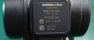
Before buying a new flow meter, pay attention to the markings of the old one. It is advisable to purchase a product with the same marking so that it is guaranteed to be compatible with the car’s ECU.
The main thing after replacement is not to forget to adapt the new flow meter. To do this, remove the negative terminal of the battery for a few minutes to expose the data in the ECU.
In some car models, this cannot be done in a garage; you will have to go to a service center where there is special diagnostic equipment.
Replacing the sensor - instructions
Using a screwdriver, unscrew the clamp of the air intake corrugation at the sensor outlet, pull it off and carefully inspect the internal surfaces of the sensor itself and the corrugation. These surfaces must be dry and clean; traces of condensation and oil are unacceptable. If the air filter is changed rarely, then dirt getting on the sensitive element of the sensor is the most common cause of its breakdown in VAZ cars.
There may be oil in the mass air flow sensor as a result of an increased oil level in the engine crankcase, or the oil sump of the crankcase ventilation system is clogged.
Next, unscrew the 2 screws of the sensor with a 10mm wrench and remove it from the air filter housing. There should be a rubber sealing ring on its front part (at the entrance edge). It prevents unfiltered air from being sucked into the intake tract through the sensor.
If the ring is out of place and stuck somewhere in the air filter housing, then there will be a thin layer of dust on the inlet mesh of the sensor itself. This is the second reason that destroys the mass air flow sensor ahead of time.
Correct assembly should take place in the following sequence: put a sealing rubber band on the sensor, check the sealing skirt, then insert everything together into the filter housing.
This concludes the visual check of the mass air flow sensor at home. You can check its operation 100% only with the help of special equipment in a car service center. For example, using a technique for assessing the oscillogram when the throttle is sharply opened to the cutoff mode (a motor tester is needed), or assessing the oscillogram when the ignition is turned on.
Resuscitation of a damaged air flow sensor is successful in no more than 5% of cases. In extreme cases, you can rinse with ethereal liquid to clean matrices and optics. It will evaporate without a trace. After making sure that there is no more dust or debris in the device, you can dry it thoroughly and put it back in place. Sometimes after such a simple procedure the device will work.
On most foreign cars, a mass air flow sensor was installed until 2000; subsequent generations of models began to be equipped with a pressure controller. Replacing a non-working sensor is simple and can be done on your own without any problems, you just need to buy a mass air flow sensor that matches the ECU firmware version. Its price is around 3,000 rubles, depending on the manufacturer.
Recommendations for increasing service life
To extend the life of the MAF sensor, follow these recommendations:
- Change the air filter promptly to minimize clogging of the flow meter.
- Monitor the technical condition of the engine, carry out maintenance on time, change and fill only with high-quality engine oil.
- If the car has a high mileage, check the engine compression - wear or jamming of the piston rings and valve seals will lead to oil penetration into the intake system. This will prevent the appearance of oil deposits on the thermistors.
- Monitor the condition of the crankcase ventilation system. This is especially true for those engines where the crankcase gas suction pipe is connected in front of the mass air flow sensor. Check the condition of the oil separator under the valve cover.
Air flow meter repair
In most cases, these devices cannot be repaired. They are simply replaced with a similar or universal one. Only those that use the pitot tube principle can be repaired. Contamination often occurs, which can impede the movement of the record.
You can deal with dirt using special sprays that are used to wash carburetors. In rare cases, you can restore the operation of this variable resistor by installing it on a board with contacts. Sometimes it is possible to cope with this problem simply by bending the plates so that the tip works on the part of the pad that has not yet been worn out.
Many specialists at service stations suggest disconnecting the device from the ECU. However, nothing good will come of it.
Thermal anemometer flow meters cannot be repaired either. But you can try to cure the Bosch air flow meter.
How to clean the mass air flow sensor
Over time, the sensitive element of the sensor can become covered with inorganic microparticles and a film formed from oil fumes, which impairs the correct air readings. The control unit program corrects the distorted sensor signals up to a certain point, but at the critical limit of the permissible range it turns on the emergency light, reporting an error in the fuel system. In addition, symptoms of a malfunction of the mass air flow sensor appear in the form of failures and fouling of the spark plug electrodes with soot.
The factory does not recommend cleaning the air flow sensor with various types of liquids, especially solvents and carburetor cleaners. You can clean the sensor by spraying the measuring element with alcohol. Cleaning the sensor with alcohol will not cause harm. Before turning the ignition key, make sure that the air path of the sensor is clean and, if foreign objects are present, remove them with tweezers or any tool suitable for this purpose.
How to replace the mass air flow sensor
If the sensor cannot be repaired, there is only one way out - replacement. Replacing the sensor is very simple.
To do this, you need to turn off the ignition and remove the connector. Then the fastening screws are unscrewed and the intake tract hose, which is connected to the filter housing, is disconnected. Next, the sensor can be safely removed and a new one installed in its place. Using these instructions, you can replace any air flow meter. Opel is no exception.