Symptoms of a problem
A mixture misfire is a failure to ignite the fuel-air mixture or its untimely ignition. In any of the cases, the system counts the number of misses and delays, and, if necessary, turns off the idle cylinder or even a pair. On most cars, the first sign of a malfunction is the “check” symbol lighting up on the dashboard.
Also among the common signs can be noted:
- Smell of fuel from the exhaust pipe. Since the mixture did not ignite in the cylinder, it is discharged almost unchanged or partially neutralized.
- Shoots in the exhaust system. If a partial fire occurs, the catalytic converter is severely damaged, which can lead to popping noises.
- Loss of power. The engine does not work properly, causing the crankshaft to spin at a lower speed, resulting in a significant loss of power.
- Engine tripping. Failure of one or a pair of cylinders leads to the fact that the engine begins to vibrate during operation and other signs of malfunction appear.
In cars with an electronic control unit, there are several types of errors that indicate a breakdown.
- P0300. It is a sign of multiple failures in the process of ignition of the combustible mixture in different cylinders.
- P0301 - p0304. The last number shows which cylinder is not working properly.
Main types of DAAZ carburetors
Of course, carburetor feed mixture supply systems are considered obsolete today. However, according to a number of criteria they are superior to injection designs. A small number of electronic components increases the reliability of the unit and ensures ease of repair work. In addition, carburetor engines do not have high requirements for fuel quality.
Carburetors can be of three types.
- Bubbler. These devices are no longer used. The principle of operation of the unit was to prepare and supply a mixture of air with the vapor fraction of the fuel.
- Membrane-needle-shaped. The assembly consists of several compartments that separate the membranes. They are connected to each other by a rod ending in a needle. This device locks the valve seat through which the fuel mixture is supplied.
- Float This type is most widely used due to its reliability, good quality of the fuel-air mixture and ease of setup. Structurally, it consists of a float-type chamber necessary for the influx of fuel and a compartment where it is mixed with oxygen.
VAZ 21074 engine control system diagram
Wiring diagram of electrical connections of ECM VAZ 21074 - circuit elements. 1 — controller connector; 2 — mass air flow sensor; 3 — coolant temperature sensor; 4 — crankshaft position sensor; 5 — throttle position sensor; 6 — oxygen concentration sensor; 7 — speed sensor; 8 — ignition module; 9 — solenoid valve for purge of the adsorber; 10 — electric fan relay; 11 — electric fuel pump relay; 12 - main relay; 13 - fuse for the power circuit of the electric fuel pump relay: 14 - fuse for the power circuit of the main relay; 15 — fuse-link; 16-fuse protecting the constant power supply circuit of the controller; 17 - diode; 18 — idle speed regulator; 19 — nozzles; X1 - diagnostic block; X2 - connection block to the vehicle electrical system.
Damage diagnostics
How to understand that an injector needs to be replaced, checked or repaired? Even without sensors, you can understand that repair of fuel system elements is required if there are 1 of 2 main signs in models 2107, 21074:
- Unstable engine operation. Sometimes it may stall or have difficulty starting.
- A much less obvious sign is loss of power. This effect is noticeable if you mostly drive at medium speeds, but at high speeds it is very noticeable.
- The last sign is recorded only by sensors - the pressure inside the system increases.
The cause of such failures is clogged injectors; even diagnostics are not needed. Cleaning helps restore the engine to its original performance. If the problem has not been resolved after cleaning, it is worth checking the tubes and injectors for damage or breakdowns. In such cases, it is better not to start repairs, but simply replace the damaged parts with new ones.
Sometimes it is impossible to determine on your own where the damage is, and only then will diagnostics at service centers come in handy. A blockage can cause quite serious damage to the VAZ 2107 injector, as well as rupture of channels. The pressure that arises inside the system can easily destroy the most fragile parts. Here you won’t be able to fix the situation with your own hands, even if you have a complete diagram of the car at hand. There is only one conclusion - you need to devote a lot of time and attention to cleaning injectors and do it regularly.
Characteristics of oils for VAZ
The service life of the engine depends on the correct selection of oil for injection VAZ 2107. The recommended quality standard for the lubricating fluid is given by the manufacturer. Any type of oil that meets API SJ/CF, SG/CD quality standards can be filled into the car.
The abbreviation API means that a lubricant meets the following basic criteria:
- cleaning properties;
- temperature regime;
- indicator of deposits on engine components before the first oil change;
- release of harmful substances;
- corrosive properties;
- effectiveness of protecting components from friction.
It is recommended to use the following types of oils.
| Oil brand for VAZ | SAE viscosity groups | API standard |
| RAVENOL LLO | 10W-40 | SJ/CF |
| SHELL HELIX SUPER | 10W-40 | SG/CD |
| TNK SUPER OIL | 5W-40, 10W-40, 15W-40, 20W-40 | SG/CD |
| TOTAL QUARTZ | 5W-40, 10W-40 | SL/SF |
| MOBIL SUPER M | 15W-40 | SJ/CF |
| LUKOIL LUX | 5W-40, 10W-40, 15W-40 | SJ/CF-4 |
| NOVOIL-SINT | 5W30 | SG/CD |
| CONSOL | 5W-40, 10W-40, 15W-40 | SG/CD |
| BIZOL GREEN OIL | 10W-40 | SL/SF |
| ESSO ULTRA | 10W-40 | SJ/CD |
| LUKOIL SUPER | 5W-40, 10W-40, 15W-40, 10W-30 | CF-4/SG |
| RAVENOL SUPER HD | 15W-40 | SJ/CF |
| LUKOIL SUPER | 5W-30, 5W-40, 10W-40, 15W-40 | SG/CD |
| ANGROL-SUPER | 5W30, 5W-40, 10W-40 | SG/CD |
| LUX | 5W30, 5W-40,10W-30, 10W-40, 15W-40, 20W-40 | SG/CD |
| ESSO UNIFLO | 10W-40, 15W-40 | SJ/CD |
Fuel consumption
- Fuel consumption in urban conditions is 9.4 liters per 100 km.
- On a flat road at cruising speed it will already be 6.9 liters per 100 km.
- In mixed mode, consumption will be from 8 to 9 liters per 100 km. Such figures do not allow us to call this engine economical, but in this case a lot depends on the driver himself.
- Another parameter that depends on the driver is oil consumption per 100 km. For the average driver of a car with this engine, it is 700 g per 100 km. This, of course, is not small, but with careful driving you can reduce this consumption down to 450-500 g/100 km.
- The weight of the 2103 engine when fully assembled is 121 kg.
Wiring harness in the cabin
In the interior of the VAZ 21074 there are wiring harnesses:
- under the instrument panel. This bundle contains the wires responsible for the headlights, direction indicators, instrument panel, and interior lighting;
- stretched from the fuse box to the rear of the car. The wires of this bundle power the rear lights, glass heater, and gasoline level sensor.
The wires that are used in the “seven” for electrical connections are of the PVA type and have a cross-section from 0.75 to 16 mm2. The number of copper wires from which the wires are twisted can range from 19 to 84. The wiring insulation is made on the basis of polyvinyl chloride, which is resistant to temperature overloads and chemical influences.
The wiring harness under the instrument panel of the VAZ 21074 contains wires that are responsible for the headlights, direction indicators, instrument panel, and interior lighting.
To simplify the repair, maintenance and replacement of electrical equipment, the factory electrical wiring of VAZ 21074 vehicles has a set color.
Table: cross-section and color of wiring of the most important electrical appliances VAZ 21074
| Electrical circuit section | Wire cross-section, mm2 | Insulation color |
| minus battery - body mass | 16 | black |
| starter plus - battery | 16 | red |
| plus generator - battery | 6 | black |
| generator—black connector | 6 | black |
| terminal “30” of the generator—white block MB | 4 | pink |
| terminal “50” starter—starter start relay | 4 | red |
| Starter start relay—black connector | 4 | brown |
| ignition relay—black connector | 4 | blue |
| terminal “50” of the ignition switch—blue connector | 4 | red |
| terminal “30” of the ignition switch—green connector | 4 | pink |
| right headlight connector - ground | 2,5 | black |
| left headlight connector—blue connector | 2,5 | green (gray) |
| terminal “15” of the generator—yellow connector | 2,5 | orange |
| Radiator fan ED - “ground” | 2,5 | black |
| Radiator fan ED—red connector | 2,5 | blue |
| contact “30/1” of the ignition switch—ignition relay | 2,5 | brown |
| pin “15” of the ignition switch—single-pin connector | 2,5 | blue |
| cigarette lighter—blue connector | 1,5 | blue (red) |
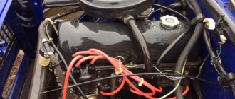
WHERE IS THE ENGINE NUMBER LOCATED?
Each vehicle model produced at the factory is equipped with an engine with a personal number. So, the engine number on the “seven” is its identification number, which can be used to determine the identity of the stolen car and its history.
The engine number is stamped on the cylinder block on the left side, immediately below the distributor. In addition, the number is duplicated in the summary table, which is attached below the air supply housing. The metal plate contains information about the car, such as model, body number, model and number of the engine unit, equipment, etc.
The number is stamped on the left side of the cylinder block
What generators can be installed on the “seven”
The design of the VAZ 2107 allows the installation of not only the G-221A generator. Therefore, if necessary, the driver can install a more powerful device, however, this will require making some changes to the electrical circuit of the car. The question arises: what is the reason for the desire of a car enthusiast to change his “native” generator?
The G-221A was the optimal device for equipping cars at the beginning of their mass production. However, a lot of time has passed since the 1980s and today almost every driver uses modern electronic devices:
- acoustic system;
- navigators;
- additional lighting devices (tuning), etc.
Accordingly, the G-221A generator cannot cope with high loads, which is why drivers begin to look for more powerful units.
You can install at least three more powerful devices on the “seven”:
- G-222 (generator from Lada Niva);
- G-2108 (generator from the G8);
- G-2107–3701010 (injection model for a carburetor car).
It is important that the last two models do not require changes in the design of either the generator housing or its mountings. When installing a generator from Niva, you will have to make some modifications
Connection diagram G-221A
Being an electronic device, the generator needs to be used correctly. Therefore, its connection diagram should not cause ambiguity. It should be noted that drivers of “sevens” can usually easily connect all the generator terminals themselves, since the circuit is accessible and understandable to everyone.
The generator (item 2) is connected to the circuit in series between the battery (item 1) and the mounting block (item 3)
Many car owners wonder where which wire should be connected when replacing the generator. The fact is that the device has several connectors and wires, and when replacing, you can easily forget which wire goes where:
- orange is not useful for connection, it can be left as is or connected to gray directly to autostart the car;
- a gray thick wire goes to the brushes from the relay regulator;
- a gray thin wire connects to the relay;
- yellow - coordinator of the control light on the control panel.
When working independently with the G-221A, it is better to sign the purpose of the wires so as not to connect them by mistake later.
To avoid errors, all wires have their own color designation
Advantages
That's what, and with positive qualities, domestic engines constantly have problems. But despite this, the advantages of such engines still exist, which is why they are used in cars even today. The main positive qualities are the following:
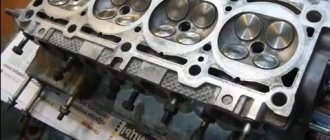
- Repairing a VAZ 2107 engine is very simple. Its design features mean that even capitalizing the engine will not be difficult. The cylinder walls are thick enough to allow the engine to be bored more than once.
- Easy to maintain. The simplest design of the motor means that it can be repaired from almost any breakdown without much difficulty. Owners of such cars carry with them only a minimum set of tools.
- The engine speed of the VAZ 2107 is distributed in such a way that the car with it under the hood is quite high-torque.
- Engine life is its main advantage. In practice, such engines can travel more than 200 thousand kilometers without the need for major repairs. Only in order to achieve such indicators is it necessary to properly maintain the power unit.
Explanation of symbols
- 1 – radiator fan drive motor;
- 2 – mounting block block;
- 3 — idle speed sensor;
- 4 – engine ECU;
- 5 – potentiometer;
- 6 – set of spark plugs;
- 7 – ignition control unit;
- 8 – electronic crankshaft position sensor;
- 9 – electric fuel pump;
- 10 – indicator of the number of revolutions;
- 11 – lamp for monitoring the health of electronic systems and the brake system;
- 12 – ignition system control relay;
- 13 – speedometer sensor;
- 14 – special factory connector for reading errors using the BC;
- 15 – injector harness;
- 16 – adsorber solenoid valve;
- 17, 18, 19,20 – fuse box for repairing the mounting block that protects the injection system circuits;
- 21 – electronic fuel pump control relay;
- 22 – electronic relay for controlling the exhaust manifold heating system;
- 23 – exhaust manifold heating system;
- 24 – fuse protecting the heater circuit;
- 25 – electronic air sensor;
- 26 – coolant temperature control sensor;
- 27 – electronic air damper sensor;
- 28 – air temperature sensor;
- 29 – pressure control sensor and low oil pressure lamp.
Differences between carburetor and injector
If we talk about functions, then there are no fundamental differences - both systems perform the task of supplying fuel from the tank to the fuel rail, then to the cylinder. However, the difference lies precisely in the methods of supplying this very fuel.
In an engine that uses a carburetor design, the mixture of fuel and air enters the combustion chamber using a pressure difference. The downside of such a system is that implementing this method requires the power of the engine itself.
As for the injection system, the fuel enters directly into the combustion chamber under some pressure. But here the fuel ingress is controlled by a computer. This is one of the main advantages of this design. Since the system, which is controlled by electronics, uses fuel in precise dosages, which makes the engine more economical.
General diagram of the electrical equipment of the VAZ 21074 injector
General diagram of the electrical equipment of the VAZ 21074 injector
1. Electrical connection diagram of the wiring harness of the instrument panel assembly LADA 21074
- — ignition switch unloading relay;
- — relay-interrupter of direction indicators;
- — windshield wiper relay;
- — brake signal switch;
- — switch for headlights and direction indicators;
- — windshield wiper and washer switch;
- — ignition switch;
- - hazard warning switch;
- — instrument cluster;
- — rear window heating switch;
- — rear fog light switch;
- — external lighting switch;
- — heater motor switch;
- — additional resistor for the heater electric motor;
- — heater electric motor;
- — indicator lamp for heated rear window;
- — brake fluid level warning lamp;
- — instrument lighting switch;
- - cigarette lighter;
- - watch;
- - reverse light switch;
- — hand brake sensor;
- — rear fog light relay;
- — block of the instrument panel harness to the ignition system harness;
- — glove box lighting;
- — mounting block.
A1, A2 - grounding points of the instrument panel wiring harness. A3 - grounding points for the heater motor.
2.Electrical connection diagram of ECM LADA 21074 injector
1 - controller; 2 — diagnostic oxygen concentration sensor; 3 — block of the ignition system harness to the right mudguard harness; 4 — block of the fuel level harness to the ignition system harness; 5 and 7 — electrical fuel pump harness pads; 6 — control oxygen concentration sensor; 8 — electric fuel pump; 9 — diagnostic block; 10 — speed sensor; 11 — idle speed regulator; 12 — throttle position sensor; 13 — coolant temperature sensor; 14 — mass air flow sensor; 15 — crankshaft position sensor; 16 — solenoid valve for purge of the adsorber; 17 — ignition coil; 18 — spark plugs; 19 — nozzles; 20 — block of the ignition system harness to the instrument panel harness; 21 — controller power supply fuse; 22 — ignition relay; 23 - ignition relay fuse; 24 — fuse for the electric fuel pump power supply circuit; 25 — electric fuel pump relay; 26 — block of the ignition system harness to the injector harness; 27 — injector harness block to the ignition system harness; A - to the “plus” terminal of the battery; B1 — grounding point of the fuel level sensor harness; B2, ВЗ — grounding point of the ignition system harness; 21074-3724026 — ignition system harness
3. Electrical connection diagram of the wiring harness of the right mudguard assembly LADA 21074.
- — mounting block;
- — block of the right mudguard harness to the left mudguard harness;
- — right side turn signal;
- - right headlight;
- — additional starter relay;
- — windshield washer pump;
- — blocks of the right mudguard harness and connecting starter wires;
- — starter;
- — rechargeable battery;
- — generator.
A1 is the grounding point for the right mudguard wiring harness. A2, A3 - grounding points of the connecting motor wire with the battery and housing.
4. Electrical connection diagram of the left mudguard assembly wiring harness LADA 21074.
- — mounting block;
- — block of the left mudguard harness to the right mudguard harness;
- - left headlight;
- — left side turn signal;
- — oil pressure warning lamp sensor;
- — coolant temperature sensor;
- — brake fluid level sensor;
- — electric motor of the windshield wiper;
- - sound signal;
- — engine electric fan.
A1, A2 - grounding points of the left mudguard wiring harness.
5. Electrical connection diagram of the flat rear wiring harness assembly for LADA 21074.
- — mounting block;
- — flat rear harness block to the ignition system harness;
- — right front door lamp switch;
- — right rear door lamp switch;
- — left front door lamp switch;
- — left rear door lamp switch;
- — right interior lamp;
- — left interior lamp;
- — electric fuel pump with fuel level indicator sensor;
- — rear window heating element;
- — additional brake signal;
- — right lamp;
- — left lamp;
- — left license plate light;
- — right license plate light.
A1 is the grounding point for the rear window heating element. A2 is the grounding point for the license plate light ground harness. A3 - A8 - grounding points of the flat rear wiring harness assembly.
Source
Schemes of individual blocks of the seven
Power supply system
Power plant starting system
1 - starter; 2 - relay; 3 — ignition switch; 4 - battery
Ignition system
1 - generator; 2 — ignition switch; 3 - distributor; 4 - breaker; 5 — candles; 6 - coil; 7 - battery
Contactless ignition system
External and internal lighting
Windshield wipers and washers
1 — electric motors of the windshield wiper; 2 — washer motor; 3 — mounting block; 4 — ignition switch; 5 - washer switch
Cooling Fan
1 — fan electric motor; 2 - sensor; 3 — mounting block; 4 - ignition relay; 5 - ignition switch.
VAZ-2107 diagram
The VAZ-2107 car was produced from 1982 to 2014. Here are colored wiring diagrams (for the injector and carburetor) with a description of all the elements for various modifications. The information is intended for self-repair of cars. Electrical circuits are divided into several blocks for ease of viewing via a computer or phone; there are also circuits in the form of a single picture with a description of each element - for printing on a printer.
The “sevens”, like most modern cars, use a single-wire circuit for supplying electricity to electrical equipment. The other terminal of the consumer is always connected to the ground of the machine to which the negative terminal of the battery is connected. This solution allows not only to simplify the design of the on-board network, but also to slow down corrosion.
Carburetor design
The unit installed on the “seven”, despite the abundance of parts, is not complicated. Knowing the structure of the carburetor, you can independently replace failed elements.
Main components of the unit:
- a float-type chamber into which fuel is dosed;
- valve to stop the flow of fuel;
- a compartment in which the mixture is mixed;
- dampers, channels, jets;
- spray;
- diffuser;
- pump to speed up the flow.
Characteristics of VAZ 2107
| Performance indicators | Meaning |
| Maximum speed, km/h | 150 |
| Fuel consumption l: | |
| City | 9,6 |
| Route | 6,9 |
| Mixed | 8 |
| Euro toxicity standard | Euro 2 |
| Engine | |
| Power unit volume, cm3 | 1451 |
| Fuel type | petrol |
| Number and arrangement of cylinders | 4/R |
| Supply system | Distributive injection |
| Number of valves | 8 |
| Maximum torque, N*m at rpm | 115 at 3450 |
| Maximum power, hp | 71 |
| Transmission | |
| Transmission type | Mechanical |
| Number of steps | 5 |
| type of drive | Rear |
| Suspension | |
| Front suspension device | Independent multi-link |
| Rear suspension device | Dependent, on coil springs |
| Front brake mechanism | Disk |
| Rear brake mechanism | Drum |
Initially, the seven was equipped with an engine with a capacity of 1.5 liters, but during the production process the power range was expanded.
Modifications of engines installed on the VAZ 2107.
| Options | Model range of VAZ engines | ||||
| 2103 | 2104 | 2106 | 21067 | 21067-20 | |
| Cylinder diameter, piston stroke | 76 80 | 76 80 | 79 80 | 79 80 | 79 20 |
| Working volume | 1,5 | 1,5 | 1,6 | 1,6 | 1,6 |
| Compression ratio | 8,5 | 8,5 | 8,5 | 8,5 | 8,5 |
| Supply system | carburetor | Distributive injection | carburetor | Distributive injection | Distributive injection |
| Rated power, kW | 52,5 | 52,5 | 54,8 | 54,5 | 53,5 |
| Rated speed | 5600 | 5000 | 5600 | 5000 | 5300 |
| Fuel brand | (AI-92) | (AI-92) | (AI-92) | (AI-92) | (AI-95) |
| Spark plug | A17DVR, FE65CPR, A17DV-10 | А17ДВРМ, BRISR, SUPER, LR 15YC | A17DVR, FE65CPR, A17DV-10 | А17ДВРМ, BRISR, SUPER, LR 15YC | А17ДВРМ, BRISR, SUPER, LR 15YC |
| Toxicity standard | Euro-0 | Euro 2 | Euro-0 | Euro 2 | Euro-3 |
Calibration data for DAAZ 2107 jets - table
Accurate dosing of the mixture of gasoline and air is carried out by jets. There are several types installed in any carburetor. Knowing the characteristics and location of parts is useful when servicing the device and adjusting its settings.
If we consider the VAZ 2107: the carburetor is equipped with the following types of jets:
Diagnostic connector
The ECU on the “Seven”, like on other cars, is also equipped with a diagnostic connector. Today, all connectors are manufactured according to the same OBD2 standard. That is, the “on-board vehicle” can be checked for errors and malfunctions using a conventional scanner with a standard cord.
The device for connecting the scanner to the ECU on a VAZ 2107 is compact in size
What is it used for?
The OBD2 diagnostic connector is equipped with a certain number of contacts, each of which performs its own function. By connecting the scanner to the ECU connector, you can carry out several diagnostic modes at once with high accuracy:
- view and decipher error codes;
- study the characteristics of each system;
- clear “unnecessary” information in the ECU;
- analyze the operation of car sensors;
- connect to execution mechanisms and find out their remaining resource;
- View system performance and saved data about previous errors.
A scanner connected to the diagnostic connector instantly identifies all errors in the operation of the ECU and deciphers them to the driver
Where is
The diagnostic connector on the VAZ 2107 is located in the most convenient place for work - under the glove compartment in the cabin under the instrument panel. Thus, there is no need to disassemble the engine compartment mechanisms in order to connect the scanner to the ECU.
Opening the glove compartment, you can see the ECU diagnostic connector on the left side
VAZ2107 carburetor: how to clean the unit from dirt, step by step
Often, malfunctions of the device are associated with its contamination.
Signs that can help diagnose the problem:
- instability of operation, especially at idle;
- high gasoline consumption;
- jolts and jerks while driving (with the gas pedal pressed).
You can clean the carburetor from blockages on your own. This requires washing the strainer located at the inlet of the float chamber. In addition, cleaning the chamber itself, as well as other components, especially the jets, will help solve the problem.
Causes of injector clogging
Typically, problems with the injection system occur when using low-quality gasoline. Heavy paraffins contained in such fuel settle on the walls of the system, cutting off the fuel supply. Manufacturers of high-quality gasoline add detergent to it - a special additive that dissolves deposits. Low-quality gasoline contains too much paraffin, which forms deposits faster than detergents can remove them.
Deposits form more intensively at low temperatures, so when the car is frequently driven with a cold engine, the injector becomes clogged more often.
Deposits can accumulate not only in the injectors. Often vapors settle on the throttle valve, which leads to a change in the proportions of the air-fuel mixture entering the cylinders.
Deposits of substances contained in low-quality gasoline may also appear on the back of the intake valve plates. This can lead to valve burnout or fuel detonation.
To clean the injection system of deposits, it is necessary to use special flushing fluid and equipment. You can wash the injector in a garage. To do this, you need a syringe and washing liquid. The latter is mixed with gasoline and poured into the injection system through the hose of the vacuum brake booster. First, the operation is performed with the engine turned off, then with the engine running. The mixture is fed into the running engine gradually, in small portions. As a result, the deposits dissolve, enter the engine cylinders and burn there. In this case, clouds of smoke may briefly appear coming out of the muffler.
The principle of operation of the carburetor
The functioning of the power unit is largely determined by the quantity and quality of the incoming fuel mixture.
How the 2107 carburetor works:
Fuel enters the float chamber, the level of which is regulated by a valve or float. After this, the gasoline, divided into droplets, enters the mixing chamber through nozzles, where mixing with the air occurs. The econostat further enriches the mixture when the engine is running at full load. Diffusers optimize the flow of fuel, which is supplied to the manifold through the throttle valves. When the engine runs at high speeds, the accelerator pump turns on.
Electrical diagram of VAZ 21074
In VAZ 21074 cars, electrical energy is delivered to consumers using a single-wire circuit: the “positive” terminal of each electrical device is powered from a source, the “negative” terminal is connected to “ground,” i.e., connected to the vehicle body. This solution simplifies the repair of electrical equipment and slows down the corrosion process. All electrical appliances of the car are powered from the battery (with the engine off) or the generator (with the engine running).
The wiring diagram of the VAZ 21074 injector contains an ECM, an electric fuel pump, injectors, and engine control sensors
Wiring diagram VAZ 21074 injector
The injection versions of the “Seven” released from the factory assembly line have the following indices:
- LADA 2107–20 - in accordance with the Euro-2 standard;
- LADA 2107–71 - for the Chinese market;
- LADA-21074–20 (Euro-2);
- LADA-21074–30 (Euro-3).
The injection modifications of the VAZ 2107 and VAZ 21074 use an ECM (electronic engine control system), an electric fuel pump, injectors, control sensors and monitoring engine parameters. As a result, there was a need for additional under-hood and interior wiring. In addition, the VAZ 2107 and VAZ 21074 are equipped with an additional relay and fuse box located under the glove compartment. The additional unit is supplied with wiring that supplies:
- fuses: main relay power circuits;
- controller constant power supply circuits;
- electric fuel pump relay circuits;
- The main thing;
Additional fuse and relay block VAZ 2107 injector located under the glove compartment
Providing electricity
The G7 is responsible for providing consumers with electricity:
- Battery voltage 12 V, capacity 55 Ah;
- generator type G-222 or 37.3701;
- voltage regulator Ya112V, which automatically maintains the voltage within 13.6–14.7 V.
Diagram of the power supply system for the VAZ 21074 injector includes a generator, battery and voltage regulator
Engine starting
The starting system in the VAZ 21074 is a starter and ignition switch powered from the battery. There are two relays in the starter circuit:
- auxiliary, which supplies power to the starter terminals;
- retractor, due to which the starter shaft engages with the flywheel.
The starting system in the VAZ 21074 is a battery-powered starter with a relay and an ignition switch.
Ignition system
In early versions of the seventh VAZ model, a contact ignition system was used, which included:
- ignition coil;
- distributor with contact breaker;
- spark plug;
- high voltage wiring.
The VAZ 21074 contact ignition system consists of a coil, distributor, spark plugs and high-voltage wires
In 1989, the so-called contactless ignition system appeared, the circuit of which included:
- Spark plug.
- Distributor.
- Screen.
- Hall Sensor.
- Electronic switch.
- Ignition coil.
- Mounting block.
- Relay block.
- Key and ignition lock.
In 1989, a contactless ignition system appeared, to the circuit of which a Hall sensor and an electronic switch were added
“Sevens” with injection engines use a more modern ignition circuit. The operation of this circuit is based on the fact that signals from the sensors are sent to the ECU (electronic control unit), which, based on the received data, generates electrical impulses and transmits them to a special module. After this, the voltage increases to the required value and is supplied to the spark plugs through high-voltage cables.
In injection "sevens" the operation of the ignition system is controlled by the electronic control unit of the ECU
Outdoor Lighting
The external lighting system includes:
- Block headlights with dimensions.
- Illumination of the engine compartment.
- Mounting block.
- Glove compartment lighting.
- Instrument lighting switch.
- Rear lights with dimensions.
- Illuminated numbers.
- Exterior lamp switch.
- External lighting indicator lamp (in the speedometer).
- Ignition.
The VAZ 21074 external lighting connection diagram will help in troubleshooting headlights and tail lights
Auxiliary equipment
Auxiliary or additional electrical equipment of the VAZ 21074 includes:
- electric motors: windshield washer;
- windshield wiper;
- heater fan;
- radiator cooling fan;
The connection diagram for windshield wipers uses:
- Gearmotors.
- ED headlight washer.
- Mounting block.
- Egnition lock.
- Washer switch.
Windshield wiper motors drive a trapezoid that moves the wipers across the windshield
Cleaning and preventing plaque in the system
The injector device is very sensitive to large inclusions in gasoline. If you are using a cheap brand of fuel, be prepared to change your injectors soon. So the first thing you should do for your VAZ fuel pump is change the brand of fuel. The power supply system of the VAZ 2107 should become cleaner; the possibility of plaque formation in the system is still not excluded. Since the flammable liquid in the channels occasionally stagnates and sometimes even freezes, an early breakdown can be prevented only in one way - regular cleaning.
Approximately every 35-40 thousand km it is necessary to carry out preventive cleaning work on the fuel system. You need to wash the channels with your own hands. The performance of the engine will depend on the quality of cleaning. If this procedure is carried out irregularly, then soon you can say goodbye to one injector and look for a new one, and then you will have to change the remaining elements of the VAZ fuel pump.
In 4-cylinder types of injection engines, different intensities of injector clogging are observed. The temperature in the area of cylinders 2 and 3 is always elevated, so sediment accumulation occurs there faster.
A special admixture of polyetheramine is considered a prophylactic agent in such cases. It prevents the accumulation of burning for a long time.
Car wiring diagram
1 – radiator fan drive motor; 2 – relay and fuse block (mounting block); idle speed sensor; 4 – engine control unit; 5 – potentiometer; 6 – set of spark plugs; 7 – ignition control unit; 8 – electronic crankshaft sensor; 9 – electric fuel pump; 10 – tachometer 2107; 11 – lamp for monitoring the health of electronic systems; 12 – ignition system control relay; 13 – speed sensor; 14 – diagnostic connector; 15 – set of injectors; 16 – adsorber solenoid valve; 17, 18, 19 – fuse block protecting the injection system circuits; 21 – electronic fuel pump control relay; 22 – electronic relay for controlling the intake pipe heating system; 23 – intake pipe heating system; 24 – fuse protecting the heater circuit; 25 – electronic oxygen level sensor; 26 – cooling system temperature control sensor; 27 – electronic air damper sensor; 28 – air temperature sensor; 29 – pressure control sensor.
How to remove, install, replace a carburetor
For repairs and maintenance, the carburetor must be dismantled. To work, you will need a set of tools (pliers, open-end wrenches, screwdrivers) and a suitable room. Work is carried out on a cold engine. In short, first you need to disconnect everything connected to the carburetor, and only then remove it. The video below clearly shows the procedure for removing a VAZ 2107 carburetor.
Sequencing:
- Loosen the clamp on the corrugated pipe for the warm air intake, remove the pipe;
- Unscrew the air filter housing fasteners and remove it;
- Remove the suction cable: unscrew the bolt and screw that secure its shell, then loosen the cable itself;
- Remove the hose for removing crankcase gases from the fitting;
- Disable the idle economizer control: remove the wires from the microswitches;
- Disconnect the vacuum ignition timing regulator tube (remove it from the fitting);
- Pull the tube off the economizer;
- Remove the return spring;
- Loosen the clamps securing the fuel hoses, remove the hoses;
- Unscrew the 4 carburetor mounting nuts;
- Remove the carburetor from the studs.
Carburetor replacement is needed less frequently than repair. You can find any spare parts for this device on sale. After adjustment, cleaning and repair, the carburetor can be put back.
The carburetor is installed in the reverse order: first it is placed on the studs, then screwed to the body, and then all communications that were removed are connected to it.
Generator set belt for VAZ 2107
The VAZ 2107 car was produced from 1982 to 2012. Initially, the model was equipped with a smooth drive belt (old model). Over time, the “seven” was modified several times and at the end of the 1990s, the generator began to work with a new type of belt with teeth.
The operation of the generator and the entire vehicle depends on the quality of the drive belt.The design numbers and sizes of the belts are indicated in the vehicle’s service book:
- 2101–1308020 (smooth surface), dimensions - 10.0x8.0x944.0 mm;
- 2107–1308020 (toothed surface), dimensions - 10.7x8.0x944.0 mm.
How to tension a belt on a generator
The operation of the generator, as well as the water pump, primarily depends on the correct tension of the belt on the pulley. Therefore, existing rules cannot be neglected. The belt is installed and tensioned in the following order.
- Place the assembled generator in place, lightly tightening the fixing nuts.
- Take a pry bar and use it to fix the gap between the generator housing and the pump.
- Place the belt on the pulley.
- Without releasing pressure from the pry bar, pull the belt onto the pulley.
- Tighten the top nut securing the generator until it stops.
- Check the degree of belt tension - the rubber should not sag, but it should not be too tight.
- Tighten the lower nut securing the generator.
Video: how to tighten the alternator belt
Checking the degree of tension is done with two fingers. You need to press the free part of the belt and measure its deflection. The optimal deflection is 1–1.5 centimeters.
Thus, we can say that independent maintenance of the generator on a VAZ 2107 is quite possible and does not fall into the category of impossible tasks
It is important to follow the recommendations and algorithms for this or that work in order to carry out quality repairs or diagnostics. However, if you have doubts about your skills and abilities, you can always turn to professionals for help.
Engine repair
The following tools will be needed for this job:
- a puller that allows you to easily remove the piston pin;
- adjustable support under the bottom, supporting at least 1 ton;
- crankshaft ratchet key;
How to remove the engine
The engine is removed for repair or replacement. There is nothing particularly complicated in the procedure if you have a special winch. In this case, it will be possible to dismantle the engine entirely, however, this is more difficult than removing it without the cylinder head.
The sequence of actions looks like this.
- It is recommended to remove the car hood to ensure easy access.
- Drain all refrigerant.
- Remove the air filter, disconnect the choke cable, remove the accelerator lever, the carburetor gas hose - in a word, all the attachments that can present an obstacle to work.
- Unscrew the muffler and remove the hose from the heater.
Now you can move on to direct work with the engine.
- Unscrew the nuts from the cushions.
It would be more effective to insert a metal pipe under the rope. Place the ends of the rope on the hydraulic equipment to lift the engine. Turn over and pull out the motor.
Replacing crankshaft bearings
The engine is removed, you can continue.
- Unscrew the 14 bolts securing the pan to the cylinder head.
- Remove the oil pump.
- Unscrew the nuts securing the connecting rods and remove the covers.
To be able to remove and replace the liners, you should remove the half rings of the thrust bearing from the grooves of the fifth main bearing bed. After disassembling the crankshaft, you can remove the old bearings and replace them. New items must match the desired category.
The inserts can only be replaced. They are not subject to repair, as they are made to exact dimensions. Over time, parts wear out and new ones have to be installed. Essentially, the bearings are plain bearings for the connecting rods that act on the crankshaft.
Replacing piston rings
In many cases, this procedure is required due to the fault of the car owner himself, who fills in something unknown instead of high-quality oil. In addition, the frequency of lubricant renewal is of great importance. The first symptom indicating failure of the rings is a sharp increase in fuel consumption.
Replacement on a removed but not yet disassembled engine.
- The crankshaft is rotated so that the required piston is in the desired position - bottom dead center.
- The connecting rod cover is removed, all pistons are pushed upward by the cylinders.
- Carbon deposits are removed from the pistons.
- Old rings are replaced with new ones.
It is imperative to first install the oil scraper ring, and finally tighten both elements with a special mandrel.
Protection of electrical circuits of VAZ 2107
The purpose of the fuse box is to protect the wires from fire and the battery from discharge in the event of a short circuit. The VAZ 2107 is equipped with a disposable fuse block, which is located under the hood near the battery - on the right on the partition between the engine compartment and the passenger compartment. This location was not chosen by chance - the fuses are located as close as possible to the battery in order to reduce the number and length of unprotected electrical networks.
The fuse location diagram is printed on the cover of the unit, which allows you to quickly navigate in the event of a blown fuse.
When replacing a failed fuse, its rating must be observed. This indicator is not marked on the cover of the fuse block, so you can find it out either from the VAZ 2107 diagram (injector) or based on the markings on the fuse to be replaced.
Important: failure to comply with the rating may lead to electrical wiring and fire. This can happen if the new fuse is rated for significantly higher current. The fuse block also contains electrical relays
The difference between the fuse block of the injection variation of the “seven” and the carburetor one is only in the presence of additional fuses for the ECM, fuel pump and other devices typical only for an injection car
The fuse box also contains electrical relays. The difference between the fuse block of the injection variation of the “seven” and the carburetor one is only in the presence of additional fuses for the ECM, fuel pump and other devices that are typical only for an injection car.
Maintenance
In order to get trouble-free operation, as well as to guarantee that the engine will work for as long as possible, you need to properly maintain it. Fortunately, this is quite simple to do, since maintenance can be carried out even in the garage. Many people wonder how much oil is in the VAZ 2107 engine, and the answer is quite simple - the block is designed for 3.75 liters, but during replacement you need to fill in 3.5.
The valves on such an engine need to be adjusted every 10 thousand kilometers. But as practice shows, owners of cars with such a power unit under the hood only do this when the car stops moving. The gasoline filter needs to be changed every 15 thousand kilometers. The chain is tensioned every 40 thousand kilometers and must be replaced after 100 thousand kilometers.
Non-ferrous metal in the engine. Is it possible to submit?
All non-ferrous metal contained in the engine can be returned at a profit if you contact a specialized collection point. Not every acceptance facility has a manipulator available, so not all organizations are able to load, transport and weigh an internal combustion engine, which can weigh up to 200 kilograms. The non-ferrous metal will not accept the entire engine, but only some of its components, which are made of non-ferrous alloys. Usually, entire engines are accepted as ferrous scrap metal, so it is better to disassemble the unit in advance and separate the parts from non-ferrous scrap. In Moscow and the Moscow region, you can hand over an old car engine at a good price. For example, VtorBaza buys scrap motor aluminum (at a price of 90-118 rubles/kg), and you can also hand over cast iron from the cylinder block of your car’s internal combustion engine. This reception point has all the necessary special equipment, loaders and trucks. helps with organizing transportation, weighing, disassembling and evaluating the engine, with its subsequent purchase. At the same time, the price for all ferrous and non-ferrous metals accepted at acceptance is higher than in other points in the region.
What metal is a car engine made of?
Each car has its own characteristics and power requirements, so the engine installed in it is selected individually. It is possible to determine which metal is used in the engine if it is dismantled and disassembled. Old engines sitting in a garage or salvaged cars are usually suitable for only one purpose - to sell the internal combustion engine for scrap. Do you want to know what metal is in the engine block to represent profit? Let's figure out what metal car engines are made of and what value they represent.