string(10) “error stat”
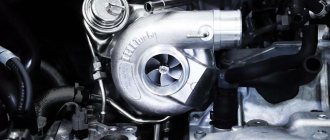
Boring of cylinder head channels provides an excellent opportunity to increase the power of a car engine. This will require some modification of the intake/exhaust channels so that the filling of cylindrical systems with fuel will undergo significant improvements. Fuel flows through the channels at very high speeds, causing any defect to slow down the flow.
Boring the cylinder head (cylinder head) requires the following steps:
- Modification (tuning) of channels - changing the diameter, establishing the correct radius of the fasteners;
- Valve seat tuning;
- Precise alignment of the manifold holes and channels of the cylinder head system;
- Surface grinding.
This activity requires special skills and special equipment. As a result of this work, the engine becomes more powerful on average by fifteen percent.
The combustion chamber
When studying combustion chamber tuning, it would be a good idea to read the article >> increasing the compression ratio as these types of tuning influence each other.
Space "ears" around the valves
If you intelligently modify the space in the combustion chamber that passes close to the valves when they open, you can significantly increase the throughput, thereby increasing the filling and power of the engine.
In a “two-valve cylinder”, if the combustion chamber has a compact structure, part of the circumference of the valve plates moves most of the way close to the edge of the combustion chamber, creating a low-flow area for the air-fuel mixture and for the release of burnt gases. If this zone is expanded, the filling of the cylinders can be increased and the power can be increased accordingly. In dome-shaped combustion chambers, or in block heads with a V-shaped arrangement of valves relative to each other, this processing technology is ineffective, since the valves, when opened, move towards the center of the cylinder and move away from the walls at a considerable distance. You need to bore to the places where the head meets the cylinder block and around the valves, creating the so-called “ears around the valves”. A gasket or an imprint of the old contact areas will help determine the area to which you can bore. Boring is carried out using cutters. Attention ! Bore very carefully, especially make sure not to get the rotating tool into the contact area of the block head seals.
Why bore the cylinder block?
Block boring is a special process through which the geometry of the machine’s engine cylinders can be restored.
It is necessary to bore the cylinder block for a number of reasons:
- Thanks to this procedure, the natural position of the mating components of the power unit relative to each other is restored.
- To restore optimal wearability and correct positioning of components relative to the surface, cylinder geometry alone is not enough. The latter will also break during operation of the power unit.
- As a result of the increased friction and stress that occurs with a lack of tolerance, other dependent units will continue to collapse. This will lead to the formation of additional loads on all moving parts of the internal combustion engine involved in the operation of the unit. As a result, cracks and bends will form on the devices, and the unit will be deformed.
- Also, the boring or honing procedure is often performed to increase the motor power parameter. Although the cylinder walls of internal combustion engines are made of high-strength steel, this material tends to wear out when the pistons operate. The shape of the cylinders ends up being more oval than round, causing the piston rings to fit together.
- As a result, due to detonation of the combustible mixture, exhaust gases enter the engine crankcase along with the mixture. This leads to a decrease in the overall power parameter of the internal combustion engine and the power unit begins to consume motor fluid.
Boring interval
The fact that the boring procedure is performed less frequently these days than it was 30 years ago is due to high technology. At that time, it was difficult to find quality oil or antifreeze for the engine. Therefore, the procedure for overhauling the unit and boring could be carried out after 50-60 thousand kilometers.
Today, thanks to the use of additives and additives in liquids by various manufacturers, wear of the unit can occur after 200 thousand kilometers. The honing procedure itself for the purpose of tuning or repair is performed on special machines where the devices are ground down. Then new, larger pistons are mounted on the power unit, which makes it possible to increase the service life of the internal combustion engine.
Artem Krupin spoke in detail about the goals pursued by cutting the channels of the motor BC head.
Valve seat sag
Valve seats sometimes have a recessed location in the combustion chamber (Valve leakage can occur as a result of major repairs, high mileage, tuning associated with increasing valve lift by installing a different camshaft, etc.) At the beginning of the opening of the intake valve (by 1-2 mm) the air-fuel mixture will experience significant difficulty in penetrating the engine cylinders.
In the case of an exhaust valve, the ledge will interfere with the cleaning of exhaust gases from the cylinders in the final exhaust phase. The presence of irregularities and sharp corners greatly affects the “cylinder purging” (a very important phase of engine operation when both valves are open to a small amount). The situation can be corrected by smoothing all sharp edges around the valve seats. It is advisable to perform all operations on processing the combustion chamber with inserted (unnecessary) valves to protect the working edges of the valve seats from damage.
Valve seat projections
When installing valve seats into the block head, ledges are formed in the intake and exhaust channels due to the imperfection of the casting itself and the straight cylindrical shapes of the seats. The interfaces between stock parts are usually not processed in any way. Even if the factory provides for machining of the joints between the valve seats and the block head, it is carried out mediocrely with the formation of new ledges, since the machining only involves passing with a milling cutter, which does not provide the required quality when machining complex, curved surfaces. Smoothing the interface between the body of the cylinder head and the valve seats gives very good results in terms of reducing flow resistance and, as a result, increasing the filling of the engine cylinders.
Increasing valve seat diameter
One of the most effective types of tuning for the cylinder head is considered to be increasing the diameter of the intake and exhaust valves.
The operation is very specific and requires the selection of new valves, valve seats and specific equipment to complete this procedure. The effect of enlarging the valves can also be achieved by boring the diameter of the valve seat by a certain small amount (depending on the circumstances). The working place of the valve seal is shifted to the edge of the valve plate. The maximum amount by which seats can be bored depends on the specific engine, the thickness and diameter of the seat. Typically, the smaller the valves and the more advanced the engine, the smaller the seats can be bored. In any case, if you increase the diameter of the seat by 0.75 - 1.2 mm, the reliability of the engine will not suffer from this, but the throughput will increase, as from a similar increase in the diameter of the valve with seats.
By the way, if the inner diameter of the seats is increased, then it is not necessary to leave the old valves; you can replace them with new ones with a larger diameter of the plate.
Cylinder head boring
Another problem of the domestic automobile industry is the presence of excess casting in the area of the guide bushings. This reduces their already small cross-sectional size. Using special ball cutters you can get rid of this disadvantage. Cylinder head boring should be done extremely carefully so as not to spoil the entire system.
It is important to know that the inner surface of the bushings cannot be made perfectly smooth, as this will lead to a deterioration in fuel evaporation. The result of this stage of tuning the VAZ cylinder head should be a perfectly round cross-section without the presence of factory casting residues. Next to this element there are other important components of the vehicle. For example, oil channel, cooling channel. Therefore, when boring the cylinder head, it is important not to damage them.
The video shows the boring of a 16-cl. cylinder head. and valve:
Refinement of the cylinder head - changing the dimensions of the valve system section
This type of VAZ cylinder head tuning solves two issues:
- Increases the cross-section of the valve system.
- Reduces all of these elements.
Unfortunately, this process will not be complete without some investment, since such modification of the cylinder head requires replacement of the guide bushings. The consequence of such an upgrade, in addition to throughput, will be a reduction in the weight of the system to forty percent of the original.
Docking the collectors with the head
The need to adjust the internal surfaces of the intake and exhaust manifolds to similar channels of the block head is due to their inaccurate manufacturing and lack of adjustment during the assembly process at the manufacturer. However, a smooth transition from the manifold to the head bores is very important for good engine filling. If all the ledges are removed, the flow of the fuel-air mixture will encounter fewer obstacles on its path and a larger amount of the mixture will enter the engine cylinders.
Adjacent surface of the intake manifold
The adjacent surfaces of the intake manifold and the cylinder head must be carefully processed until a complete fit is achieved.
To begin with, it is advisable to place the manifold on pins to firmly fix the manifold relative to the block head. Next, mark the places of inconsistencies with a “marker” (alternatively, coat the surfaces with paint, separate them after drying, when broken, the places of metal protrusions on both surfaces will be visible) To prevent the marks from being erased, scratch along the contour with an awl, then treat the surfaces with cutters until a complete joint is obtained. 2 Method. Use plasticine
1. Apply plasticine to the docking area and partially inside the cylinder head channels. 2. Sprinkle with fine shavings, dust, etc. A separating material is needed to prevent the surfaces from sticking together when joining. 3. Attach the manifold to the cylinder head and tighten with bolts until the plasticine is not completely squeezed out of the crack. There should be 0.5-1mm left 4. Disconnect the manifold and the prints will show where the cylinder head material protrudes. 5. Draw a line with an awl and cut off the excess with cutters. 6. Repeat the procedure for the manifold, since the first 5 points determine the protrusion zone of the cylinder head only.
Operations to identify processing sites (metal removal), block heads for better docking with collectors.
3 Method. Use the manifold gasket. The gasket must be applied alternately to the mating surface of the cylinder head and manifold. When marking the places where metal will be removed, pay special attention to the accuracy of the alignment of the fastening holes or pins, since they are landmarks.
I’ll deviate a little from the topic and note that it would not be superfluous to dock and smooth out all the sharp ledges of all the parts located at the inlet, since they create very significant resistance to the flow of the air-fuel mixture.
Parts that create intake resistance for injection or carburetor systems:
— Steps connecting the throttle to the intake manifold and the intake manifold — Imperfect shape of the throttle valve — Imperfect shape of the mass air flow meter — Imperfect shape of the intake manifold — Corrugated intake manifold — Air filter — Carburetor junction with the intake manifold and thermal insulating insert
Exhaust manifold contact surface
If the exhaust manifold has the same internal diameters of the pipes as those on the cylinder head, then they also need to be joined. if the holes in the exhaust manifold pipes are significantly larger than the holes in the cylinder head, then there is no need to bore the head, because this measure was made specifically to limit the back pressure from the exhaust system back into the cylinders. (the exhaust gases experience significant resistance when meeting the step formed by the smaller hole on the cylinder head.)
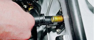
Replacement process
If signs of damage to the gasket are detected, it should be replaced immediately.
Set of tools
To carry out the replacement procedure you need to prepare:
- set of wrenches;
- pliers;
- screwdriver;
- torque wrench;
- coolant container;
- clean rags.
A set of necessary tools
The car must be washed before replacement to prevent dirt from getting into the disassembled engine.
Enlarged inlet and outlet channels
Increasing the diameter of the inlet and outlet channels reduces the resistance to the movement of gases, but the speed of their movement also decreases. Which is good for high-speed engines and bad for a motor without calculating its operation at high speeds. Increasing the diameter of the channels is ineffective without increasing the diameter of the valves. In this regard, it is necessary to either bore and repress the seats for large valves, or bore existing seats by a small amount in order to increase the diameter in the valve area, and not just the channels themselves.
Cutting off part of the guide
The intake and exhaust valve stem sits in the middle of the ports, creating significant resistance on the intake and exhaust.
The situation is aggravated by the presence of a protruding part of the valve guides and the tide flowing around them. In “hard” tuning, all protruding parts are cut off, and the valve stem is ground to a smaller diameter. It is not recommended to reduce the valve stem by less than 10%. It is better to process the protruding end of the guide from the outside to obtain a more streamlined shape, this is more difficult and less effective in terms of filling, but cutting off part of the guide reduces its length and greatly increases wear, especially when using a camshaft with increased valve lift. When the guide protrusion is completely cut off, you can somewhat compensate for its wear by replacing conventional bushings with bronze ones, which have much higher wear resistance than conventional ones. Tuning valve guides
Machined valve guides for less flow resistance.
Complete cutting of the valve guides to ensure even better cylinder filling. To the detriment of the durability of the valve mechanism.
Combustion chamber parts
Modified intake and exhaust valve.
The combustion chamber. Piston crown. It is not visible to the naked eye, but under a microscope, the smooth metal looks like mountain ranges with a mass of protrusions and depressions. Polishing smoothes out these irregularities, thereby reducing the actual contact surface area. When polishing the metal, the contact area of the burnt gases with the surfaces inside the combustion chamber is reduced, due to which the heat transfer is reduced and the gases, when expanding, can do more useful work, because if the temperature of the gas decreases, its pressure also decreases, which leads to a loss of power.
You can learn more about heat losses by following the link >> Heat losses
Another plus arising from the first:
Since less heat is lost into the metal, the temperature of the working surfaces (piston, valves, combustion chamber) decreases, which has a beneficial effect on the engine’s knock resistance and resistance to overheating. Also, polishing and smoothing all sharp corners reduces aerodynamic drag during the movement of gases at the inlet and outlet. (especially when passing through narrow gaps, during the initial opening of the intake valve, purging, etc.) Polishing prevents carbon deposits, reduces stress concentration, reducing the possibility of cracks in the combustion chamber and valves. For those who find polishing difficult. Advice! Try polishing with a special felt wheel for an angle grinder. Costs about 100 rubles. At high speeds, using regular goya paste, polishing goes very quickly and is a lot of fun!
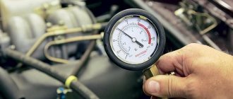
Preparation for sanding
For self-grinding, we will first need a set of feeler gauges and a metal ruler, with its help we will determine how strongly the cylinder head is bent and the degree of its unevenness. This is more of a method by eye, since only visually can you understand where and how much it costs to grind. In addition to such unevenness, there may also be cracks and similar defects. This indicates that the engine overheated well and detonated. To identify such cracks, it is worth painting the cylinder head with slow-drying paint and wiping it off after a few minutes. Where the paint remains there will be a crack. It is advisable to use bright colors of paint. Unfortunately, only large cracks can be seen, but microcracks can only be seen with the help of special instruments.
In any case, no matter how bent the cylinder head is, the first thing you need to do before starting grinding is to check for both large and micro cracks.
What should not be polished
There is no need to polish the inlet and outlet channels. Firstly, due to inaccessibility, polishing internal channels is very long and tedious. Secondly, at the inlet, due to the very smooth surface, a film of gasoline is formed which periodically breaks off into the flow, forming uneven operation of the engine at low loads. Polishing has a particularly detrimental effect on an engine with a carburetor power supply system and single injection, since the air-fuel mixture moves through the entire intake tract, completely passing through the intake channels. For channels, a sanded smooth surface is sufficient, without unnecessary and sometimes harmful polishing.
A little theory
The operation of supercharged and naturally aspirated engines requires a different approach. The intake tract of an inflatable engine is less demanding in terms of quality than the aspirated tract. Let's start with one simple thing. When I was studying at Polytechnic University, a professor of gas dynamics hammered into us one axiom. When you are designing any air duct with a circular cross-section, first ensure that there are no obstacles, 90-degree turns, etc. along the entire length. That is, if the diameter of your path is 35 millimeters, make it so that a ball of this size can run through it from beginning to end, and only then add your own swirlers, etc. This is what I follow when I start fine-tuning any cylinder head.