Removal
1. Place the car on an inspection hole or overpass (see “Preparing the car for maintenance and repair”).
2. Remove the cylinder head from the engine (see “Cylinder head gasket - replacement”).
4. Unscrew the nuts of the connecting rod caps (without removing the crankshaft) and push the piston and connecting rod out of the cylinder block (see “Crankshaft - removal and installation”).
5. Remove the steel-aluminum liner from the connecting rod cover.
The connecting rod and cap are stamped with the number of the cylinder in which they are installed.
6. Place the connecting rod in a vice and remove two compression rings and one oil scraper ring with an expander from the piston.
7. Press the pin out of the connecting rod through the mandrel and remove the piston.
Similarly, remove the pistons of the remaining cylinders.
Before installing the piston group on the connecting rod, it is necessary to select its parts.
Selection of connecting rod and piston parts
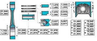
1. Select the piston to the cylinder. The calculated gap between the cylinder and the engine piston should be 0.06-0.08 mm. It is determined by measuring the cylinders and pistons and is ensured by installing pistons of the same class as the cylinders. The maximum permissible gap is 0.15 mm. The piston diameter is measured in a plane perpendicular to the piston pin, at a distance of 52.4 mm from the piston bottom. The outer diameter of the pistons is made into five classes (A, B, C, D and E) every 0.01 mm, and the diameter of the piston pin hole is made into three categories every 0.004 mm. Spare parts include pistons of groups A, C and E. The piston class (letter) and the category of the piston pin hole (number) are stamped on the piston bottom.
For correct orientation of the piston relative to the cylinder, there is a “P” mark on the piston wall (next to the boss), which should be directed towards the front of the cylinder block.
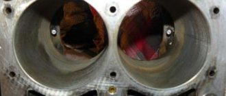
We measure the cylinder diameter with a bore gauge in four zones, both in the longitudinal and transverse directions of the engine.
In belt zone 1, the cylinders practically do not wear out. Therefore, by the difference in measurements in the first and other belts, we judge the amount of cylinder wear.
Scheme for measuring cylinder diameters:
1, 2, 3 and 4 - belt numbers; A and B - measurement directions
The cylinders are divided into five classes by diameter every 0.01 mm: A, B, C, D and E. The cylinder class is stamped on the bottom plane of the block.
2. We select the finger to the piston. The pin is installed in the upper head of the connecting rod with tension and rotates freely in the cylinder bosses. According to the outer diameter, the fingers are divided into three categories every 0.004 mm. Categories are indicated by a colored mark on the end of the finger: blue - the first category, green - the second, red - the third. We check the mating of the piston pin and the piston by inserting the piston pin (lubricated with engine oil) into the holes of the piston bosses. The piston pin must be installed by simply pressing the thumb and not fall out when the pin is in a vertical position.
3. Check the gap between the grooves and piston rings. The gaps must correspond to the values given in table. 8.1.3 (see below). An increased gap leads to rapid wear (breaking) of the piston grooves.
Table 8.1.2. Dimensions of the main mating parts of the engine
Piston - cylinder (for VAZ-2103 engine)
Piston - cylinder (for VAZ-2106, VAZ-21011 engines)
2nd category (green mark)
3rd category (red mark)
Piston pin - upper end of connecting rod
Table 8.1.3. Gaps in the mating of grooves and piston rings
Upper compression ring - piston groove
Lower compression ring - piston groove
Oil scraper ring - piston groove
Table 8.1.4. Gaps in piston ring locks
Upper compression ring
Bottom compression ring
Assembly of connecting rod and piston group
1. Place pin 4 on mandrel 2 without tightening stop 3 too much.
2. Cool the connecting rod pin in the freezer. We heat the upper head of the connecting rod to 240°C with a blowtorch or an industrial hair dryer, clamp the connecting rod in a vice and put the piston on it (the “P” mark on the piston should be located on the side of the oil outlet hole on the lower head of the connecting rod).
3. Push the pin mounted on the mandrel into the holes of the piston bosses and the upper head of the connecting rod until the annular belt 1 on the handle stops in the piston.
4. After the connecting rod has cooled, lubricate the pin with engine oil through the three holes in each piston boss and through the gap between the boss and the connecting rod.
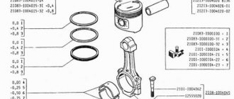
5. Lubricate the piston rings and grooves with engine oil. We install the rings on the piston and orient the ring locks. The upper compression ring lock should be located at an angle of 30-45° to the piston pin axis, the lower compression ring lock should be directed in the opposite direction, and the oil scraper ring lock should be at an angle of 30-45° to the piston pin axis between the compression ring locks. We install the lower compression ring with the groove facing down. If the ring is marked “TOP”
or
“TOR”
, it should be directed towards the bottom of the piston. The joint of the oil scraper ring spring expander should be located on the side opposite to the ring lock.
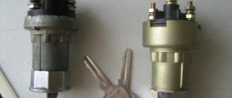
Carrying out compression measurements in cylinders
Let's look at an example of working on classic VAZ models. It is necessary to measure compression on a warm engine. Readings from a cold engine can distort the picture. For measurements, you will need a special pressure gauge equipped with a threaded tip. It can be bought at any auto store.
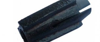
Compressometer appearance
The check begins by unscrewing all the candles from their sockets. Then the central cable from the ignition coil is disconnected. We set the gear to neutral and turn the throttle valve to the maximum opening. After this, screw the compression gauge into one of the spark plug holes. At this time, an assistant must turn the starter handle. Two or three pumps will be enough.
The readings are considered normal if the data on the device is 12-13 ks/cm2.
Level 10 to 12 is also acceptable. But if the numbers are below 10 kg/cm2, then this indicates low compression. If compression still reaches a satisfactory level, but a little late, then the valves may be responsible.
To clarify, you can pour about 20 ml of oil into the disputed chamber and crank the starter again, taking a measurement. When normal compression is established at 12 kg/cm 2, the reason lies in the rings. Correct installation of the piston rings can solve this problem. If the pressure remains low, then the valves are the cause of the decrease.
Installation using a mandrel
↑ Procedure for replacing pistons on a VAZ 2106
We remove the piston with connecting rod from the cylinder block.
Steel-aluminum liners are installed in the lower heads and connecting rod caps.
They are prevented from turning by locks inserted into the slots of the beds.
We clamp the connecting rod in a vice and, unclamping, remove the upper and lower compression rings. When installing them subsequently, the “TOP” or “TOP” mark should be directed towards the piston bottom.
There may not be an inscription on the ring, but the lower compression ring is always installed with the chamfer facing down.
Remove the oil scraper ring with the expander.
Having installed the piston on a wooden mandrel with a hole or holding it suspended, we knock out the pin.
We assemble the connecting rod and piston group in the reverse order.
We select a new piston. The piston class is indicated by a letter, and the pin category is indicated by a number (see table of mating parts).
The gap between the piston and cylinder for new parts is 0.05–0.07 mm. When worn, the maximum allowable gap is 0.15 mm.
A correctly selected finger, lubricated with engine oil, should fit into the piston holes under the force of the thumb and not fall out of the piston in a vertical position.
↑ Installation of piston rings
Having installed the ring in the cylinder, use a set of feeler gauges to check the gap in its lock. It should be 0.25–0.40 mm for all rings. If the gap is increased, the rings must be replaced.
We also check the gap between the ring and the piston groove with a set of feeler gauges. For the upper compression ring it should be 0.045–0.077, the lower one – 0.025–0.057, the oil scraper ring – 0.020–0.052 mm. The maximum permissible wear gap is 0.15 mm.
We install the rings in the piston grooves, then orient them as follows:
- We orient the upper compression ring lock at an angle of 45° to the piston pin axis;
- turn the lock of the lower compression ring relative to the lock of the upper ring in the opposite direction;
- We set the oil scraper ring lock at 90° relative to the locks of the other rings. In this case, the joint of its expander should be on the opposite side of the lock of the ring itself.
↑ Finger installation
We heat the upper head of the connecting rod to 240°C, holding it in a vice.
The finger can be pre-cooled in the freezer.
We put the piston on the connecting rod and, using a mandrel, quickly press the pin.
↑ Markings on the piston, connecting rod and cover
The numbers on the connecting rod and its cover, indicating the cylinder number, must be on the same side and coincide.
The “P” mark on the piston should be directed toward the front of the cylinder block.
4.8.5.6 Checking the clearances between the piston grooves and piston rings
Checking the gap between the piston rings and the grooves.
The location of the piston rings in the grooves of the engine piston mod. 2106
Tool for removing and installing piston rings
Check the height gap between the grooves and rings as shown in Fig. Checking the gap between the piston rings and grooves by inserting the ring into the corresponding groove.
Check the gap in the piston ring lock with a set of feeler gauges, inserting the rings into a gauge having a hole diameter equal to the nominal diameter of the ring with a tolerance of ± 0.003 mm. If there is no gauge, it is possible to check the gap. by inserting the piston ring into the cylinder where it will work, and pushing it with the piston to a depth of 20–30 mm from the bottom edge of the cylinder.
The gap should be between 0.25 and 0.4 mm for all rings. If the gap is insufficient, the joint surfaces should be filed down, and if it is too large, the rings should be replaced.
Heights and end installation gaps of piston rings
Piston ring kits
As spare parts, rings are supplied as a set for one engine.
Rings of nominal size are used when replacing worn rings for cylinders of nominal size. To reduce the break-in period of rings in cylinders that have already been running, compression rings that are not coated with chrome are installed in the upper grooves of the pistons.
Rings with an increased diameter are installed in cylinders bored to repair size, or they are used to replace worn rings in such cylinders.
The rings are installed in the piston grooves so that the groove on the outer surface of the second (scraper) ring faces down, and the chamfers on the outer surface of the oil scraper ring face up (Fig. Location of piston rings in the piston grooves of the engine mod. 2106 ).
If this condition is not met, oil may penetrate through the rings into the cylinder, which will lead to carbon formation on the walls of the combustion chamber, smoky exhaust from the muffler and increased oil consumption. Putting rings on the piston, as well as removing them, should only be done in a special device or with special pliers (Fig. Device for removing and installing piston rings ), ensuring the same bending stress around the circumference of the ring.
After replacing the piston rings, the vehicle speed should not exceed 60 km/h within 1000 km.
Piston repair: what you should pay attention to
Modern materials and technologies for manufacturing parts make it possible to operate the engine under very intense conditions. The maximum crankshaft rotation speed reaches one hundred revolutions per second. In this case, the piston and connecting rod reach a translational speed of up to 30 m/sec twice for each revolution (two hundred times per second). and the same number of times they come to a complete stop, causing huge cyclic inertial loads (the weight with such acceleration increases by more than a thousand times). Therefore, technologists try to make the piston as light as possible, making it from an aluminum alloy with a cast steel plate that compensates for thermal deformations. The piston has stiffening ribs and hard anodizing, up to the fire zone, which protects the bottom and the groove of the upper compression ring from burning out. Friction is reduced by the most advanced brands of oils with additives. But it is impossible to avoid wear, so periodically, after a certain mileage, the piston VAZ 2106 is replaced. It is better to do this when the first symptoms appear:
Operating a car with wear and tear can lead to damage that will require major repairs, which will increase the price many times over.
How to dismantle the piston yourself
First of all, it is necessary to thoroughly wash the engine, since after disassembly it will be difficult to prevent grains of sand and dirt from getting inside. The engine must be placed on a sturdy rack at a height convenient for work. Prepare rags, a set of tools and accessories:
- socket, ring wrenches and heads 10 mm., 12 mm., 13 mm., 14 mm., 17 mm., 19 mm., 22 mm., and wrench 36 mm.;
- a set of thin flat probes;
- bore gauge;
- micrometer;
- calipers;
- torque wrench;
- device for compressing rings on the piston;
- bushing for installing piston pins;
- gas-burner;
- hammer;
- core;
- portable lamp;
- large flathead screwdriver.
Tip: Before disassembling with your own hands, all parts are marked with a core, and a photo of the initial location is taken with the numbers and marks of the removable parts so that they can be installed in their place if they are suitable.
Disassembly sequence
- The engine with the head, pan and side covers removed is laid on its side to allow access to the pistons and connecting rods. Wrench 36 mm. the crankshaft is rotated to the position of maximum extension of the nuts of a pair of connecting rods.
- Using a head and a long wrench, you need to unscrew two nuts each, securing the connecting rod cap of the first and fourth cylinders, you can use any one, but it is more correct to follow the chosen sequence. By lightly tapping with a hammer, the cover moves out of place, allowing you to easily remove it from the studs. It is advisable to first familiarize yourself with the stages of work via video.
Tip: The caps and connecting rods form a pair; during their manufacture, the final boring of the mounting hole is done in assembled form, so they are marked with the cylinder number and cannot be replaced. You need to make sure that the numbers match when assembling and are directed in the same direction.
- Using the wooden handle of a hammer, resting against the pin, the connecting rod with the piston is pushed out through the upper plane of the cylinder block. The crankshaft is rotated to the maximum extension position of the nuts of the other two connecting rods. All four pistons are disassembled in the same way. The main bearings are unscrewed and the crankshaft is removed for visual inspection.
Attention: The main bearing caps are marked with marks; it is very important to place them only in their place, since they are not interchangeable; this is required by the boring technology and assembly instructions.
- The liners are removed from the connecting rods and covers. When repairing a VAZ 2106, the piston rings are replaced, starting with the upper compression ring, all the rings are sequentially removed from the pistons, and the piston pins are knocked out with a bushing. If possible, it is better to use a press. The parts and the block are washed with kerosene, blown with compressed air, the cooling and lubrication channels are purged.
- Sanded surfaces are wiped and checked for damage. For inspection, a portable lamp is used, changing the angle of illumination to conveniently examine small scratches. Cracks are not allowed; if they are detected, defective parts will have to be replaced, including the block.
- Wear is measured using a bore gauge in four planes located from the top plane at a distance of 5mm, 15mm, 50mm. and 90 mm. In each plane, two measurements are taken in perpendicular directions.
Diagram of cylinder diameter measurement planes
- In the area of the first plane, the cylinder practically does not wear out, so the difference in size will indicate the degree of wear. If wear exceeds 0.15 mm, or there are wear or scratches on the cylinder walls, the block must be bored until they are completely removed and brought to the required size and cleanliness class by honing.
When it is necessary to replace pistons on a VAZ 2106, the cylinders are bored to one of five standardized sizes that determine the accuracy class, designated in Latin letters:
Crankshaft installation process
Before installing the crankshaft on the VAZ 2106, you need to wash, clean and dry the cylinder block. And only after that read the process.
Tools
To complete the installation you will need the following tools:
- a set of keys;
- Screwdriver Set;
- micrometer;
- consumables (liners, seals, half rings);
- torque wrench.
Set of repair tools
If defects in the form of scratches, burrs, or signs of wear are found on the surface of the liners, they must be replaced. The earbuds cannot be adjusted. When using the removed bearings further, you need to check the gap between them and the main and connecting rod journals of the crankshaft. For main shafts, the permissible size is 0.15 mm, for connecting rods - 0.10 mm. If the dimensions exceed the permissible limits, the liners are changed to a greater thickness after boring the necks. If the journals are properly ground and the appropriate bearings are selected, the crankshaft should rotate freely.