There are times, especially in winter, when car owners need to recharge their car battery from an external power source. Of course, for people who do not have good skills in working with electrical engineering, it is advisable to buy a factory battery charger ; it is even better to purchase a starting charger to start the engine with a discharged battery without wasting time on external charging. But if you have a little knowledge in the field of electronics, you can assemble a simple charger with your own hands .
general characteristics
To properly maintain the battery and extend its service life, recharging is required when the voltage at the terminals drops below 11.2 V. At this voltage, the engine will most likely start, but if parked for a long time in winter, this will lead to sulfation of the plates and, as a result, a decrease in capacity batteries. When parked for a long time in winter, it is necessary to regularly monitor the voltage at the battery terminals. It should be 12 V. It is best to remove the battery and take it to a warm place, while not forgetting to monitor the charge level .
The battery is charged using constant or pulsed current. When using a constant voltage power supply, the current for proper charging should be one tenth of the battery capacity . If the battery capacity is 50 Ah, then a current of 5 amperes is required for charging.
To extend the battery life, battery plate desulfation techniques are used.
The battery is discharged to a voltage of less than five volts by repeated consumption of a large current of short duration. An example of such consumption is starting a starter .
After this, a slow full charge is carried out with a small current within one ampere. Repeat the process 8-9 times. The desulfation method takes a long time, but according to all studies it gives good results. It must be remembered that when charging, it is important not to overcharge the battery. The charge is carried out to a voltage of 12.7-13.3 volts and depends on the battery model. The maximum charge is indicated in the documentation for the battery, which can always be found on the Internet.
Overcharging causes boiling , increases the density of the electrolyte and, as a result, destruction of the plates. Factory charging devices have charge monitoring and subsequent shutdown systems. to assemble such systems yourself without sufficient knowledge in electronics.
Schematic diagram
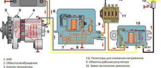
The starting charger circuit contains a triac voltage regulator (VS1), a power transformer (T1), a rectifier with powerful diodes (VD3, VD4) and a starter battery (GB1). The charging current is selected by the current regulator on the triac VS1, its current is regulated by the variable resistor R2 and depends on the battery capacity.
The input and output charging circuits have filter capacitors, which reduce the degree of radio interference during operation of the triac regulator. Triac VS1 provides regulation of the charging current when the network voltage varies from 180 to 220 V.
The triac wiring consists of R1-R2-C3 (RC circuit), dinistor VD2 and diode bridge VD1. The time constant of the RC circuit affects the opening moment of the dinistor (counting from the beginning of the network half-cycle), which is included in the diagonal of the rectifier bridge through the limiting resistor R4. The rectifier bridge synchronizes the switching on of the triac in both half-cycles of the mains voltage. In the “Regeneration” mode, only one half-cycle of the mains voltage is applied, which helps clean the battery plates from existing crystallization. Capacitors C1 and C2 reduce the degree of interference from the triac in the network to acceptable levels.
DIY assembly diagrams
It is worth talking about simple charging devices that can be assembled with minimal knowledge in electronics, and the charge capacity can be monitored by connecting a voltmeter or an ordinary tester.
Charging circuit for emergencies
There are times when a car that has been parked overnight near the house cannot be started in the morning due to a discharged battery. There can be many reasons for this unpleasant circumstance.
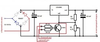
If the battery was in good condition and slightly discharged, the following will help solve the problem:
- DC voltage source 12-25 volts.
- Current limiting resistance.
A laptop charger is perfect as a power source . It has an output voltage of 19 volts and a current of within two amperes, which is quite enough to complete the task. On the output connector, as a rule, the internal input is positive, the external circuit of the plug is negative.
As a limiting resistance, which is mandatory, you can use a cabin light bulb. You can also use more powerful lamps , for example, from larger dimensions, but this will create an extra load on the power supply, which is very undesirable.
An elementary circuit is assembled: the negative of the power supply is connected to the light bulb, the light bulb to the negative of the battery. Plus goes directly from the battery to the power supply. Within two hours the battery will receive a charge to start the engine .
From a power supply from a desktop computer
Such a device is more difficult to manufacture, but it can be assembled with minimal knowledge of electronics. The basis will be an unnecessary block from the computer system unit. The output voltages of such units are +5 and +12 volts with an output current of about two amperes. These parameters allow you to assemble a low-power charger, which, if assembled correctly, will serve the owner for a long time and reliably . Fully charging the battery will take a long time and will depend on the battery capacity, but will not create the effect of desulfation of the plates. So, step-by-step assembly of the device:
- Disassemble the power supply and unsolder all wires except the green one. Remember or mark the input locations of black (GND) and yellow +12 V.
- Solder the green wire to the place where the black one was located (this is necessary to start the unit without a PC motherboard). In place of the black wire, solder a lead, which will be negative for charging the battery. In place of the yellow wire, solder the positive lead for charging the battery.
- You need to find a TL 494 chip or its equivalent. A list of analogs is easy to find on the Internet; one of them will definitely be found in the circuit. With all the variety of blocks, they are not produced without these microcircuits.
- From the first leg of this microcircuit - it is the lower left one, find the resistor that goes to the +12 volt output (yellow wire). This can be done visually along the tracks in the diagram, or using a tester by connecting the power and measuring the voltage at the input of the resistors going to the first leg. Do not forget that the primary winding of the transformer carries a voltage of 220 volts, so you need to take safety precautions when starting the unit without a housing.
- Unsolder the found resistor and measure its resistance with a tester. Select a variable resistor that is close in value. Set it to the desired resistance value and solder it in place of the removed circuit element with flexible wires.
- By starting the power supply by adjusting the variable resistor, get a voltage of 14 V, ideally 14.3 V. The main thing is not to overdo it, remembering that 15 V is usually the limit for working out the protection and, as a result, shutting down.
- Unsolder the variable resistor without changing its setting, and measure the resulting resistance. Select the required or closest resistance value from several resistors and solder it into the circuit.
- Check the unit, the output should have the required voltage. If desired, you can connect a voltmeter to the outputs on the plus and minus circuit, placing it on the case for clarity. Subsequent assembly occurs in reverse order. The device is ready for use.
How to choose the right button to install instead of the ignition switch
As you can understand, the launcher button works when it is pressed for a certain time. During this period, the starter rotates the crankshaft and the engine starts, after which the button is released. When choosing a part, you need to consider a number of features
First of all, attention should be paid to fixing the button. It is best when the contacts close when pressed and open when released
If you install a latching button, then in order to open the contacts after starting the engine, you will need to quickly press it again, which is not very convenient.
If we talk about the button itself, today there are many different solutions offered. The part can be selected based on price, quality or other characteristics. In addition to the fact that the button can be illuminated, the material of manufacture also varies (plastic or metal). Since the device is designed for constant operation and a large current will flow through it, these indicators should be taken into account when choosing
Taking into account such operational features, it is advisable to give preference to buttons that are covered with high-quality materials. Such a part will retain an attractive appearance for a long time and is characterized by resistance to abrasion
In addition, you should not choose cheap options, as they will burn out quickly enough.
When installing the system, it is important to choose a high-quality button so that the part is resistant to abrasion and can withstand heavy loads
Helpful advice
When using devices without automatic battery charge control, you can use the simplest network, daily relay made in China. This will eliminate the need to monitor the time the unit is disconnected from the network.
The cost of such a device is about 200 rubles. Knowing the approximate charging time of your battery, you can set the desired shutdown time. This ensures that the electricity supply is cut off in a timely manner. You can get distracted by business and forget about the battery, which can lead to boiling, destruction of the plates and failure of the battery. A new battery will cost much more
Use of PP22 transformers
Transformers of the PP22 type are very common today. The coils in this case are used with copper winding. Their density is quite high, and they can last a long time. However, such devices still have disadvantages. First of all, it should be noted that models with the specified transformer suffer from increased output voltage. Thus, sudden surges in the network can lead to complete overheating of the capacitors.
Resistors also often fail. If the device has an indication system, the diodes will burn out due to overvoltage. It is necessary to install transformers on the model only with seals. At the same time, the toggle switch is suitable for the P2 series. In turn, indicators are often used in the IN3 class.
Precautionary measures
When using self-assembled devices, the following safety precautions should be observed:
- All devices, including the battery, must be on a fire-resistant surface.
- When using the manufactured device for the first time, it is necessary to ensure full control of all charging parameters. It is imperative to control the heating temperature of all charging elements and the battery; the electrolyte should not be allowed to boil. The voltage and current parameters are controlled by a tester. Primary monitoring will help determine the time it takes to fully charge the battery, which will be useful in the future.
Assembling a battery charger is easy even for a beginner. The main thing is to do everything carefully and follow safety measures, because you will have to deal with an open voltage of 220 volts.
A decrease in the car's battery charge will lead to problems starting the engine. In order to ensure the functionality of the battery, the car owner can use different devices. One of these is a starter charger for a car battery.
Answers to 5 Frequently Asked Questions
- Will I need to take any additional measures before charging the battery in my car?
– Yes, you will need to clean the terminals, since acid deposits appear on them during operation. The contacts need to be cleaned very well so that current flows to the battery without difficulty. Sometimes motorists use grease to treat terminals; this should also be removed. - How to wipe charger terminals?
— You can buy a specialized product in a store or prepare it yourself. Water and soda are used as a self-made solution. The components are mixed and stirred. This is an excellent option for treating all surfaces. When the acid comes into contact with soda, a reaction will occur and the motorist will definitely notice it. This area will need to be thoroughly wiped to get rid of all the acid. If the terminals were previously treated with grease, it can be removed with any clean rag. - If there are covers on the battery, do they need to be opened before charging?
— If there are covers on the body, they must be removed. - Why is it necessary to unscrew the battery caps?
— This is necessary so that the gases formed during the charging process can freely exit the case. - Is there a need to pay attention to the electrolyte level in the battery?
- This is done without fail. If the level is below the required level, then you need to add distilled water inside the battery. Determining the level is not difficult - the plates must be completely covered with liquid.
How to assemble a starter-charger with your own hands (step-by-step instructions)
Universal instructions for assembling a ROM with your own hands:
- The assembly can be carried out on different bases, but it is better to choose a textolite plate on which the transformer assembly is fixed. It is installed first because it is the largest component of the ROM.
- Fixing parts and passing electrical lines on the plate is done by drilling holes of appropriate sizes.
- Transformers, resistors, transistors and other components are installed on the board. Their presence is determined by the specific scheme. Fixation is carried out depending on the type of component - using self-tapping screws, glue or soldering. All parts are soldered together using a tin alloy.
- When the device circuit includes rectifying diode elements, a cooling system will be required. It is possible to use special metal jackets. If they are not enough for high-quality cooling, the circuit can be supplemented with fans from desktop computers.
It is necessary to consider heat-removing blinds on the body; this will be required for heat removal. The case may not be used, but its presence will protect the device from various external influences.
How to assemble a 6 V device yourself?
For assembly you will need a transformer device; the best option is to use a separating mechanism. The electric coil will be mounted on the top of the transformer. To prevent accelerated winding output when using ROM, the consumer must make the basis for the device in advance.
Metal or wooden plates or a box are used as the base material:
- If metal is preferred, then assembly will require a welding machine. Separate attention should be paid to the isolation of the ROM, otherwise its use may lead to injury to the consumer.
- When wood is preferred, you should choose a box of the right size. The top part will be removable; the consumer should be able to dismantle it. If it is necessary to supplement the ROM with a power control device, the mechanism is mounted in the upper part of the device.
How to make a 10V charger?
To assemble a 10-volt starting charger, you need to select the device body. It can be made of wood, but during installation it is important to take into account the dimensions of the transformer device. If you give preference to analog mechanisms, then the foundation must be made strong. 10-volt models are equipped with a more powerful transformer, so handles are installed on the device body, in its upper part, for easy transportation. The transformer assembly itself is mounted in the center of the housing, and then the damper is installed.
What should you consider when choosing a ROM?
Despite the fact that over a period of time a certain rating of starter-charger models has been formed, which can be found below, the most popular and popular model is not always suitable in each specific case. When purchasing a device, you need to base it on your needs, situation and capabilities. To choose the most suitable ROM, you need to consider several basic characteristics, which are described in detail below.
Watch this video on YouTube
Maximum starting current
One of the most important parameters that you need to pay attention to when choosing a starting charger is the magnitude of the starting current. This indicator is measured in amperes and shows the amount of charge that is transferred to the battery when using the device.
To choose the most suitable model, you need to start from the engine size of the car for which you are purchasing the device. For small cars, a device with a starting current of up to 200 amperes is sufficient. If the engine is larger, then it is better to give preference to a ROM with a starting current of 300 amperes.
Support voltage
As for the output voltage indicator, it is recommended to purchase a device with this indicator of 19 Volts. Despite the fact that the vehicle's on-board network operates at a voltage of 12 volts, in the case where it is impossible to start the engine due to a discharged battery, a higher voltage will be required, even when starting the engine normally.
Dimensions and weight
Such parameters of the ROM depend on the further conditions of its operation. If a car enthusiast has a garage and there is no need to have the device with him all the time, then it is better to purchase a more powerful ROM, which can weigh on average 20 kg.
If a car enthusiast does not use a garage, but leaves his car in the parking lot and prefers to have the ROM with him, then the best option is to purchase a lighter and more portable device, the weight of which does not exceed 10 kg, and the width and height are 20 and 40 cm, respectively.
Additional options and features
Regarding various additional functions, it would not be a bad idea to purchase a device equipped with various protection systems, for example, if the car owner mixed up the terminals when connecting the device to the car’s on-board network.
It is also worth giving preference to devices that allow you to regulate current and voltage indicators. Using this function, you can independently select the required value depending on the situation and the condition of the battery.
When purchasing, you should pay attention to the material from which the device body is made. It is better to give preference to devices with a metal body or made of high-strength plastic
Such models can last for a long time.
Video “How to build an adjustable ROM”
User valeriyvalki spoke in detail about the procedure for assembling an adjustable ROM with a description of all the features and components that were used for development.
The battery is a faithful friend and assistant in the most difficult situations, but, unfortunately, it does not last forever. It would be okay if the battery died instantly, without hope of recovery. But it gradually loses its characteristics, so it often turns out that it is simply impossible to turn the starter. The peak of battery failure occurs in winter, when it is especially difficult for equipment to start in cold weather. And then either a neighbor in the garage comes to the rescue with wires for lighting, or a spare battery. Or a good starting device, which every thrifty car enthusiast has.
General information
Starting an internal combustion engine (ICE) in the cold season is a big problem. In addition, in the summer when the battery is dead, this is quite a difficult task. The cause is the battery. Its capacity depends on the service life and viscosity of the electrolyte. The condition or consistency of the electrolyte depends on the ambient temperature.
At low temperatures, it thickens and the chemical reactions necessary to power the starter slow down (the current decreases). Batteries very often fail in winter, since it is very difficult for the car to start, and more current is consumed than in the summer. To solve this problem, car starter-chargers (RODs) are used.
Don’t know how to make a winch from a starter with your own hands? Be sure to read the detailed and very interesting material from our expert.
Types of starting devices
Having some skills in radio electronics, we assemble a starting device for a car with our own hands. We will show drawings and photos, but first we will decide on its type, since they are different. Regardless of the type, it is important for us, as users, that the PU can work without the help of a battery and starts the engine not at the limit of its capabilities, turning red and smoking, but working stably even in severe frost. This is the most important condition when choosing a ready-made charging and starting device or assembling it yourself.
There is no special pickle here. The mechanism can be one of four types:
- pulse;
- transformer;
- battery;
- capacitor.
The essence of the work of each of them ultimately comes down to supplying the on-board electrical network with a current of the required rating and voltage, 12 or 24 volts, depending on the type of electrical equipment on board.
Selecting a simple transformer-based circuit
ROMs of any type perform the same task - they help start the car. However, when assembling a starting charger for a car with your own hands or buying it, it is worth remembering that there are several varieties of internal electronic filling:
- working on a transformer;
- delivering energy from a special separate battery (boosters);
- capacitor type;
- pulsed.
Since we are talking about the simplest ROMs that you can assemble with your own hands, we will further consider the first type of circuits listed above.
How to choose a transformer
To make the device yourself, it is enough to find a suitable transformer, and for a reliable start it must produce at least 100 A and a voltage of 12 V, if we are talking about a passenger car. If you ask a fifth grader, he will be able to calculate the power. In our case, it is 1.2, or better yet 1.4 kW. Without a battery, it will hardly be possible to start the engine with such current, because the starter needs at least 200 A. A standard battery will help spin the crankshaft, and while rotating, the starter consumes no more than 100 A, which is what our device will produce.
The core area cannot be less than 37 cm², and the primary winding wire must be at least 2 mm². The secondary is wound with copper wire with a cross-section of 10 squares, and the number of turns is selected experimentally so that the open circuit voltage is no more than 13.9V.
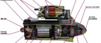
Starting the PD-10U starting engine manually
In the event of a malfunction of the batteries or starter, it is possible to start the PD-10U starting engine manually. The launch is carried out in the following order:
1) – Remove one by one both halves of the flywheel housing together with the starter;
2) – Wrap the tip of the starter wire with insulating material and tie it to the tractor;
3) – Place the starting cord assembly into one of the grooves on the flywheel of the starting motor and wind the cord around the flywheel clockwise when looking at the starting motor from behind, from the flywheel side. The second end of the cord must be passed between the fingers encircling the cord handle.
It is strictly forbidden to wrap the cord around your hand, as the reverse flash may pull your hand onto the flywheel;
4) – Pull the end of the cord towards you. The starting motor should start working. Video of manual starting of the starting and main engine of the MTZ tractor.
If engine operation does not start from the first rotation of the flywheel with a cord, then the start should be repeated. If you cannot start the engine after several attempts, then it is necessary to drain the accumulated fuel condensate from the engine crankcase. To do this, you need to disconnect the wire from the spark plug, unscrew the drain plug and, turning the crankshaft with a cord behind the flywheel, blow out the crank chamber.
After starting the starting engine, you should open the carburetor air damper and, by adjusting the opening of the throttle valve, warm up the starting engine, allowing it to operate first at a low number of revolutions, and then at a normal speed, limited by the regulator.
It is not recommended to idle (without cranking the main engine) for more than three minutes to avoid overheating of the starting motor.
Diagram and details of PU assembly
Calculating the parameters of a transformer is not all. The device works like this. We connect the power wires directly to the battery terminals, while there is no voltage at the output of the control unit until the battery voltage drops below the response threshold of the thyristors, which are indicated in the diagram. As soon as the voltage at the battery terminals drops, the thyristors open the input and only then the electrical equipment is powered by the device. As soon as the voltage at the battery terminals rises to 12 V, the thyristors close and the device automatically turns off. This allows you to save the battery from overload.
The thyristor version can be assembled using two methods - using a full-wave circuit and using a bridge circuit. If the rectifier is a bridge rectifier, then the thyristors must be selected twice as powerful. That is, according to the first scheme, thyristors are rated at a minimum of 80 A, and with a bridge circuit - at least 160 A. Diodes are rated for a current of at least 100 A. These elements are easily recognized by their braided output tip. The KT3107 transistor can be replaced with the 361st. There is only one requirement for resistance in the control circuit - their power must be at least one Watt.
The output wires, naturally, must correspond to the current and, as a rule, for this they take an analogue from a welding machine. Naturally, they are no thinner than the secondary wire. The wire that connects the network has a cross-section of each core of at least 2.5 square millimeters. A simple and reliable assembly that will start the engine in any frost. However, there are other options that you can buy in the store.
Memory circuit for Rassvet 2
Look in the picture at the diagram of the Rassvet 2 charger. It is compiled according to the original charger. If you master this scheme, you will be able to independently create a high-quality copy that is no different from the original sample. Structurally, the device is a separate unit, closed with a housing to protect the electronics from moisture and exposure to bad weather conditions. It is necessary to connect a transformer and thyristors on the radiators to the base of the case. You will need a board that will stabilize the current charge and control the thyristors and terminals.
Pulse charger starting device
A pulse device is an excellent option when you need to constantly monitor your battery and keep it in working condition. Such designs operate on the principle of pulsed current conversion, and they are assembled on microprocessors and controllers. It cannot show much power, so it may not be suitable for starting, especially at severe subzero temperatures, but it is excellent for charging batteries.
They are compact, low in price, weigh very little and look nice. But the low power, or rather the low starting current that they produce, will not allow you to start the car with heavily discharged banks in the cold. In addition, precision electronics do not tolerate voltage surges and current frequency surges, which are not uncommon in our networks, and if something happens, not even every workshop can repair such a device.
6V device
The circuit of the starting-charger of this type of transformer implies the use of a threshold one. But first you need to make a strong case for the model. It is quite easy to do it without the help of others. For this purpose, sheets began to be selected with a thickness of about 2.3 mm. With all this, the base needs to be further strengthened. To do this, many experts advise constructing a base using a welding machine. After which the transformer is installed. At the same time, the coil should be located next to it. In this case, it is best to select a low-frequency damper.
The output voltage should be at a level of 5 V. It is also necessary to emphasize that ROM expanders for a car of this type are only suitable for dynamic ones. Field capacitors are used. To install them, all contacts are first cleaned. Specifically, the soldering of parts occurs using a blowtorch. At the end of the work, the proper clamps are selected for the battery.
Mobile control units
Another type of PU, or rather two at once, similar in principle of operation - battery and capacitor. A capacitor device works by discharging charged capacitors upon command. Their composition cannot be called particularly complex, but capacitors of such ratings themselves are quite expensive and cannot be restored after damage or drying out. They are used very rarely, although they are quite mobile, but due to high unregulated currents there is a risk of harming the battery.
Boosters, or battery starters, work even simpler. By and large, this is just an additional battery in a self-contained case. It was their autonomy that brought them popularity. They can be used even in the steppe, where there is no electricity. The pre-charged battery is connected to the on-board power supply and quietly starts the engine. In this case, it is important to choose the booster capacity and its starting current. It cannot be less than that of a standard battery. Household autonomous units have a capacity of 18 A/h, while more expensive and bulky, professional devices can have a capacity of about 200 A/h.
Any of these driver assistants will help start the engine, but there is nothing more reliable and cheaper than a transformer PU assembled by yourself. Good luck to everyone and have a quick start!
It’s also important to know: 3 nuances about operation
The homemade product differs somewhat in its method of operation from the factory version. This is explained by the fact that the purchased unit has built-in functions that help with operation. They are difficult to install on a device assembled at home, and therefore you will have to adhere to several rules during operation.
- A self-assembled charger will not turn off when the battery is fully charged. That is why it is necessary to periodically monitor the equipment and connect a multimeter to it to monitor the charge.
- You need to be very careful not to confuse “plus” and “minus”, otherwise the charger will burn out.
- The equipment must be turned off when connecting to the charger.
By following these simple rules, you will be able to properly recharge the battery and avoid unpleasant consequences.
Motor pump problems and their elimination
The engine does not start.
A breakdown that can be caused by various reasons. For elimination:
- First of all, we check whether there is fuel in the pump tank. Sometimes it is enough to add gasoline.
- When the oil sensor indicates a low level, the engine must be filled with the correct fluid to the required level to operate.
Check that the equipment is turned on correctly. The motor pump can only be started in a horizontal position. A closed fuel valve can also cause the engine to become silent. To make it work, open the tap and unscrew the drain plug located in the lower part of the carburetor chamber. Wash the filter with gasoline, “blow” it with air to clean it and put it back in place. Check whether the carburetor choke is closed and clean. It is possible that oil is getting into the combustion chamber of the motor pump. To avoid this, remove the spark plug and turn the engine crankshaft while pulling the starter cord several times. Make sure the air filter and spark plugs are clean. If the latter has carbon deposits, feel free to clean it off. Be sure to screw the candle tightly when inserting it into place.
Unstable operation of the motor pump.
- The cause of the problem may be a dirty air filter. It needs to be cleaned or replaced.
- The speed controller may be faulty. In this case, only specialists can help.
Problems with the pump part of the motor pump (no suction).
Most problems of this type are caused by either damaged parts or improper operation. In order to fix:
- Check the intake hose - it may be sucking in air due to damage.
- The pump seal may also draw in air. If this is the problem, the part must be replaced.
- There must be sufficient water level in the pump section.
- The drain plug must be tightened securely.
Low performance of the motor pump.
If the equipment initially worked at 5 stars, but recently it is barely pumping water, try the following instructions:
- Clean the intake filter and check that the water level is sufficient.
- Incorrect connection to the intake hose and mismatch in diameter. In this case, correct installation is required.
- If there is water in the outlet hose or, conversely, it is blocked, the motor pump cannot operate at full capacity. By opening the valves and releasing the liquid from the hose, productivity can be increased.
Equipment overheating.
- The ambient temperature for normal operation of the motor pump should not exceed +40°C.
- If the motor pump is operated at an altitude of more than 2 km above sea level, the unit must be adjusted before operation.