For M-74, the process of turning off the immobilizer will look like this:
Disconnect the battery, disconnect the immobilizer control unit from the network. A harness with cables and a double switch is connected to the immobilizer. The circuit is connected to the battery and computer using a VAG-COM adapter. The first button of the switch is activated, it “gives the go-ahead” to change the code. The code is changed in the WinFlash program. First of all, in the settings you select the module type and the information transfer speed parameter. The second switch button is activated; it is responsible for communication between the computer and the immo control unit. The standard lock code is retained, and the Eeprom cell data is overwritten. The whole process takes a long time, but you need to wait for contact. Upon completion of the recording process, the control unit is connected back to the vehicle network, and the battery is started.
Two autostart connection schemes
Priora where is the oil pressure sensor located photo 16 valves
Autostart is implemented in different equipment models in different ways. Typically, two wires coming from the “power” connector must be connected to the gap in the standard wiring connected to the starter (pin “50”):
Autostart and alarm Starline A91
What is indicated above is the first option, but not the only one. Before installing an alarm system on a VAZ, ask how autostart works in it. Perhaps an “alternative” version of the scheme is used:
Autostart, Tomahawk brand equipment
Here, as you can see, there are two different circuits connected at the “T” point.
If the scheme is implemented in the first way, most likely, the signaling system is designed like this: by turning the key to the “Start” position, the owner initiates the triggering of the crawler. If the second option is used, the latter cannot be true. Thus, all crawler modules that have 4 taps (2 for antenna and 2 for power supply) are not applicable in any way in the second case.
“Thin” wires – antenna terminals
The connection is made through a break in the standard wiring or using inductive coupling. Both options are discussed below.
ECU pinout on Lada Vesta
The electronic control unit of the M86 Lada Vesta car uses a 55 pin controller. List of sensors connected to the Lada Vesta control unit:
- throttle position;
- oxygen flow sensor;
- brake pedal position;
- crankshaft position;
- refrigerant pressure;
- gas pedal position;
- inlet air temperature;
- oil pressure;
- coolant temperature.
Access to the car's electronic unit is made through a special connector.
Assignment of OBD2 contacts in order:
- Reserve.
- J1850.
- Reserve.
- Weight.
- Signal equipment ground.
- J2284 CAN HIGH.
- Channel K.
- Reserve.
- Self-diagnosis codes - Service Check System.
- J1850.
- Reserve.
- Programming contact.
- Immobilizer.
- J2284 CAN-LOW.
- Channel L
- Power supply 12V.
Different communication protocols use their own sets of contacts. If output No. 7 is present and No. 2 is connected, then ISO 9141 and ISO/DIS 14230 are used. The presence of connection No. 7 indicates the SAE J1850 Variable Pulse Width Modulation or Pulse Width Modulation protocol. Diagnostics uses an OBD2 cable, part number J1962, for all communication protocols.
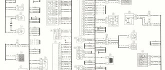
Schematic diagram (pinout) of connecting the front wiring harness on the Priora
Everything about the timing belt: what it is, explanation, where it is, how to find out what needs to be changed, types, prices, photos
The front part of the vehicle's electrical circuit is designed to supply voltage to the primary and auxiliary power circuits of the vehicle's on-board systems. The decoding of contact group chips is as follows:
- 1 – starter power supply;
- 2 – battery;
- 3 – charge supply from the generator;
- 4 – connecting block for the bundle (1 – 3);
- 5-7 – power supply to the device;
- 8 – engine compartment lighting lamp;
- 9-10 – head light;
- 11 – brake expansion tank level indicator;
- 12 – outside temperature;
- 13 – washer drive;
- 14 – external indication of reverse gear;
- 15 – cooling system fan;
- 16 – stove reducer;
- 17 – reserve resistor;
- 18 – wiper drive;
- 19 – interior relay and fuse module;
- 20 – stove motor;
- 21 – sound alarm indicator;
- 22 – horn power supply;
- A1/2, B1/2 – mass.
How to change the brushes of a Priora generator without removing
Often, replacing generator brushes on a Lada Priora is done with your own hands. First of all, this is due to savings. Many car services charge a significant fee for this procedure. With the average cost of replacing this part on other VAZ models being 400-500 rubles, for Lada Priora they will charge 2500-3000 rubles for such a service. This is explained by the fact that the generator needs to be removed, and sometimes other parts in the engine compartment will have to be unscrewed. So it turns out that replacing generator brushes on a Priora at a service station costs as much as half a new generator, which is not very cost-effective.
The process of replacing brushes without removing the generator
So, if you decide to replace the brushes with the regulator yourself, then the algorithm of actions is as follows:
- Disconnect the battery.
- Remove the power wire from the generator.
- Disconnect the control lamp input.
- Remove the plastic cover of the generator by unlatching the three latches.
- Unscrew the two fastenings of the voltage regulator with brushes.
- We change the node.
- Putting everything back together.
- Optionally, you can check the battery charging voltage and compare it with the values shown by the on-board system.
How to bypass the immobilizer
Review of the updated Lada Niva - photos, options, specifications
If a malfunction occurs in the anti-theft system, the car cannot be started with the key, the immobilizer sends a signal to the ECM to block the main systems. If the need arises to install autostart, the driver has a question about how to disable the Priora immobilizer himself.
Using a crawler
The use of an immobilizer crawler allows you to use the autostart procedure for a vehicle without dismantling or disabling the APS. You can make a device to bypass the system yourself or buy it and install it at a service station.
A simple walker consists of a relay, an inductor for pumping power to the chip, and a diode. A working key is wound to the coil, the circuit is mounted in parallel to the standard pumping coil.
Without a lineman
At the service station, a procedure is carried out to reflash the engine ECU in order to disable the immobilizer. If you have an adapter, laptop and software, you can perform this operation yourself.
To do this you need:
- Disconnect the negative cable from the battery terminal.
- Gain access to the ECM, disconnect the unit from the vehicle network.
- Remove it from the car.
- Remove the cover from the ECU, solder the resistor on the board to a position that allows reprogramming.
- Connect the board to the adapter that provides communication with the computer and supply power to it.
- Using the program, erase data from non-volatile EEPROM memory.
- Save changes, disconnect from computer.
- Resolder the resistor to its original place.
- Install the ECM into the vehicle's electronic system.
When this operation is carried out, the engine ECU stops receiving signals from the immobilizer.
Resolder the chip in the control unit
If there is no adapter and it is possible to supply power to the ECM during programming, it is recommended to unsolder the EEPROM memory chip. In its place, put a new clean chip or the same chip, but only reset it using a programmer.
See » Operating instructions for the StarLine A62 CAN alarm system and how to enable autostart
Disconnect the control unit
Physically disabling and removing the immobilizer from the Lada Priora is not possible, because it is integrated into the car’s comfort unit circuit. Disabling the power supply unit will disable the vehicle.
How to flash Bosch ECU 7.9.7+
Here I will tell you how you can flash the ECU of a VAZ 21703 Lada Priora, since I myself decided not to pay anyone money and do it myself, everything worked out and works great, and those who say and scare you that nothing will work out for you simply they want to get money out of you!
I won’t lie, you will still have to spend around 1000 rubles. to purchase an adapter and firmware, but it’s worth it, after that you can upload any firmware to your taste and do it to your friends for a small fee and get the money back, and drink beer.
For this we need:
Universal adapter KL-Line BM9213 USB MASTER KIT for tuning a car with an injection engine, you will not chip the carburetor with it,
You can read more about it and how to purchase it here. For the adapter you will need a virtual COM port driver for Win XP, Vista can be downloaded here, you can also use another adapter VAG COM USB KKL v409.1 which you can buy from our partners, this is the same KK-Line adapter only in a housing and for ridiculous money.
Next, to flash the chip firmware, we will need ChipLoader 1.96, you can also use the newer version of ChipLoader 1.97.7, but the previous one also works stably, so I don’t see the need to use the new one.
in the Help > Help tab you will find the User Guide, also go to the settings and uncheck all the boxes as shown in the figure above. In order for the block to start sewing, it needs to be modified according to the instructions in the User's Manual, everything is described in detail there.
You will also need firmware, if you just want to try chipping, then first you can try the free Tuned VAZ firmware, but I would advise you to immediately flash the normal VAZ Commercial firmware, the difference is significant.
Also, many beginners wonder why ChipLoader gives an error after selecting a 260 kB firmware?
The answer is simple, ChipLoader supports firmware only in full-size format, i.e. “Decrypt” size is 832 KB (851,968 bytes) to decrypt the firmware we need the SMS Enigma new v 1.10 program
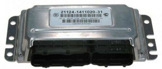
First, you need to remove the ECU to read the inscription on the sticker, then you need to determine its type, you can do this here, my sticker looked like this:
I have identified my unit as Bosch 7.9.7+; in order to program it, it needs to be modified; it is written how to do this here
Next we need to assemble a simple circuit, I made it simply from thick wires so that they could fit onto the ECU pins.
I took the 12 volt power supply from 8 1.5V batteries, you can use a power supply, but only a stabilized one, do not use pulsed ones from the computer from the one from which you will be sewing, units from Sega Dandy consoles and other Chinese equipment are not suitable, it is better to take power from batteries straight from the car, and sew on a laptop without connecting to the network, or use an uninterruptible power supply in case the power suddenly goes out
We disassemble our block and solder the resistor on the board
after reprog return it back.
connecting to the connector is not difficult, the outermost outputs are numbered, the rest can be counted, the connector looks like this:
It is advisable to follow the connection sequence: install the driver on the adapter, it is a virtual com port, and in the settings change it to COM-1, Connect the wires according to the diagram to the ECU, switch S1 should be turned down (see diagram) S2 is disconnected, then we connect everything with Master Kit Adapter or VAG COM USB KKL v409.1 (plus circuits to the plus of the adapter, GND - circuits to GND - adapter, we do not connect the power, insert the adapter into the USB, it is detected, now we connect the 12 volt power to our circuit, in a few seconds turn on the S2 switch (this is the ignition), run the ChipLoader1.96 program and select your virtual port there, click establish a connection, if it’s established, select the firmware and click load, you don’t need to erase anything, if it’s not installed, turn off S2, wait a few seconds and repeat the procedure, everything is sewn fine.
After flashing the firmware, we install the unit in place and connect to the diagnostic block according to this diagram:
and be sure to reset self-learning using InitECU. everything is ready, congratulations, you are now chipun
Source
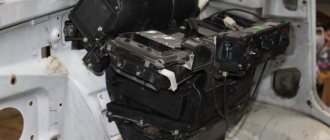
Removing and installing the computer on a Priora
When the plug is removed, you need to find two nuts securing the ECU from the bottom to the metal strip. This can be clearly seen in the photo below.
It is necessary to unscrew the nuts securing the plastic strip on which the controller is located.
When both nuts are loosened, we move the bar towards the engine compartment literally 1 cm, after which we lift it up a little and move it to the side for removal.
Now we pull out the Priora engine control unit towards ourselves so that we can carry out further actions.
Now we unfold the block in such a way that it is more convenient to disconnect the block with the power wires. Next, you need to pull out the locking frame using a screwdriver or by hand, as shown in the photo:
And now the controller connector is disconnected without any problems.
Installation of a new control unit occurs in the reverse order of removal. It is advisable to carry out a similar procedure with the battery disconnected. If you need to replace the ECU on a Priora, then a new unit will cost at least 6,500 to 10,000 rubles. A used controller purchased from a disassembly unit can be purchased for 3,000 rubles.
Priora ECU - how to regain control of the immobilizer?
The electronic engine control unit (ECU) on a Lada Priora car is located under the instrument panel and is an electronic control center that receives signals from all system sensors and, based on this data, the ECU adjusts the operation of fuel injection and other vehicle systems. The electronic control unit is removed to replace it with a new one (it cannot be repaired and is replaced properly in the event of a breakdown) or when carrying out other work in which its presence will interfere with the progress of their implementation. Prepare a standard set of tools and perform the following sequence of actions:
- Now you need to remove the fixing bracket of the connector with wires. To do this, grab it by the two protrusions and move it along the connector plane until it stops.
- Disconnect the connector with wires from the ECU.
- Do not completely unscrew the two nuts securing the control unit bracket.
- And by moving the bracket to the right and lifting it a little, we remove it along with the block.
- Replace or make any other repairs, then install in reverse order.
Lada Priora is a fairly successful and popular representative of the VAZ family. Although this sedan was declared by the manufacturer as a complete improvement of the previous model (VAZ 2110), in reality it turned out to be a qualitatively new car with its own characteristics. In addition to the delight of participating in the design development of an Italian studio, we are interested in the electronic “filling” of the car. And first of all, this is the ECU.
Electrical diagram of the dashboard (Torpedo) VAZ-2170 Priora
Part of the on-board network is designed to power the main group of vehicle equipment. The control and display elements of the instrument panel are concentrated here. The wiring supplies power to loaded parts and critical components:
- 1-3 – contact group of the front harness;
- 4 – supply voltage to the aft connector;
- 5 – power supply from the fuse panel;
- 6 – contact group of stops;
- 7 – instrument panel indication;
- 8 – control of illuminators;
- 9 – contact group of emergency airbags;
- 10 – horn;
- 11 – power supply of the diagnostic unit;
- 12 – on-board PC control;
- 13 – ignition coil controller;
- 14 and 15 – supply voltage to the EUR control unit;
- 16 – control of power window equipment;
- 17 – alarm relay;
- 18 – wiper regulator;
- 19 – air flow distributor for the ventilation system;
- 20 – stove;
- 21 – heater drive;
- 22 – heated rear wind window;
- 23 – onboard clock;
- 24-25 – radio connection;
- 26 – emergency warning button;
- 27 – glove compartment lighting;
- 28 – control button for the glove box illumination;
- 29 – bundle of wiring for ignition;
- 30 – to the emergency airbag control board.
- Central unit of body electronics Lada Vesta and XRAY (description, reviews) » Page 2 » Lada.Online
- Where is the VAZ 2110 and 2112 ECU 8 and 16 valves faulty and replacing the ECM
- Fuse box diagram for VAZ 21099 injector
- How to make a sound amplifier for a car with your own hands, assembly diagram of the device and its power supply for a car subwoofer, radio and speakers UMZCH rating
How it works and what blocks it
The immobilizer on Priora is designed to prevent theft of a vehicle by intruders. It consists of the following parts:
- APS unit, structurally combined with electrical package.
- A sensor, the presence of a key with a “native” chip in the form of a pumping loop wound around the ignition switch.
- Connecting wires for signal transmission.
- Keys with transponder.
When purchasing a car, the owner is given a special key with a red insert, which contains a chip that allows you to train working keys, and 2 working keys with programmable chips. The training key must be kept at home, because it gives access to setting up keys that the APS will consider “native”.
After activating the immobilizer and learning the working keys, the car can be started. But, only if the anti-theft unit “sees” the key with the transponder and a code is written in the chip that matches the information stored in the non-volatile memory of the APS.
In Priora, the immobilizer works as follows:
- When the working key is turned in the ignition switch cell, a voltage pulse is applied to an inductive coil wound around the lock, which excites electromagnetic oscillations in space.
- The switch contains an inductance in which the current strength changes, which allows it to receive a pulse from the pump loop.
- The capacitance is charged, supplying power to the chip with the code.
- The chip generates a return pulse, which is emitted into space and received by the pump loop.
- The signal enters the APS, where the codes stored in the block’s memory and the received codes are compared.
- If the data matches, the anti-theft device does not interfere with the operation of the engine ECU. If the codes do not match, the APS goes into protective mode, transmitting a signal to the ECU, which blocks power to the fuel pump, starter and ignition of the car.
Types of ECU memory
In order to perform its functions, the controller has to operate with a lot of data. Some of them are constantly in operation, others are loaded periodically. Therefore, memory is divided into three types:
- PROM is a programmable read-only memory device. It contains the so-called firmware - a program that controls engine operating parameters, such as fuel injection timing, ignition angle advance control, idle speed, as well as calibration data. This type of memory is retained when there is no power. Data changes are made using reprogramming.
- RAM is a random access memory device. Performs the same function as the RAM of a regular computer - temporary storage of information during one working session. This memory receives sensor data, stores diagnostic codes, as well as intermediate information about the activity of the microprocessor. It requires electric current to operate.
EPROM is an electrically programmable memory device. This type of memory is part of the standard anti-theft system. When starting the engine, the immobilizer control unit transmits codes to the Priora ECU, where password codes are located that allow or prohibit the start. In addition, the EPROM records deviations in engine operation. This memory does not depend on the supply of electricity and stores information in the controller permanently.
What block does the Priora have?
a block on the engine
cylinders similar to the cylinder block of the VAZ 21126. Among the positive aspects of the engine, one can note a reduction in noise and fuel consumption. The engine is also characterized by increased environmental friendliness and power.
Interesting materials:
How to pass the outpost level in metro 2033? How is a neural network trained? How is a heart cardiogram performed? How do menstruation work for premenopausal women? How is registration in Privat24 carried out? How does the deal work on Yulia? How to pass through walls in Fallout 4? How to pass through walls in Oblivion? How does permanent makeup heal? How to get directions in Yandex Taxi?
Types of ECU memory
In order to perform its functions, the controller has to operate with a lot of data. Some of them are constantly in operation, others are loaded periodically. Therefore, memory is divided into three types:
- PROM is a programmable read-only memory device. It contains the so-called firmware - a program that controls engine operating parameters, such as fuel injection timing, ignition angle advance control, idle speed, as well as calibration data. This type of memory is retained when there is no power. Data changes are made using reprogramming.
- RAM is a random access memory device. Performs the same function as the RAM of a regular computer - temporary storage of information during one working session. This memory receives sensor data, stores diagnostic codes, as well as intermediate information about the activity of the microprocessor. It requires electric current to operate.
- EPROM is an electrically programmable memory device. This type of memory is part of the standard anti-theft system. When starting the engine, the immobilizer control unit transmits codes to the Priora ECU, where password codes are located that allow or prohibit the start. In addition, the EPROM records deviations in engine operation. This memory does not depend on the supply of electricity and stores information in the controller permanently.
Brains priors 16 valve
This product was chosen by 6 customers
An electronic control unit (ECU) is a computing device whose main task is to process information coming from input sensors and, based on this information, to issue control commands to various vehicle systems. The operation of systems and assemblies of a modern car directly depends on the correct operation of this “think tank”. Any malfunctions in the electronic unit are immediately reflected in the operation of the power supply, transmission, exhaust system and other elements.
Suitable for Lada Priora cars (VAZ 2170, 2171, 2172) 2004-08 with a 16-valve engine, with air conditioning, Euro-3 (2 oxygen sensors).
Characteristics of the immobilizer on Priora
Before you activate or disable the immobilizer yourself, let's look at the main characteristics. How to find the device, what is its operating principle and what disadvantages will the car owner have to face? We will answer these and other questions below.
Operating principle and device
The standard alarm system works on the principle of exchanging information with the control unit, depending on the situation, allowing or prohibiting engine starting. The immobilizer can only allow the engine to start if it successfully reads the key code. If the system does not recognize the key, then when you try to start the engine, the immobilizer will block the fuel pump circuit, as well as the ignition system. The procedure for exchanging information between the immo and the control unit is carried out via the K-Line diagnostic line. This means that there is a possibility that the system settings may be disrupted by interference from mobile gadgets, in particular if the ignition is activated (video author - Pavel Master).
In addition, you need to take into account that in cars with immobilizer it is undesirable to completely discharge the battery. In this case, chaotic data may be recorded in the system memory, which will require a trip to the service center. As for the device, it is identical to the APS-4 systems, which have been successfully used in VAZs since the early 2000s. The only difference is that the code itself is integrated into the ignition key, and the reader must be located in the steering column. It should also be noted that the activated immo can control the rear fog lights and power windows.
The design of the device is based on a microcontroller based on PIC16C65B, as well as a K-Line circuit designed to exchange information via the diagnostic bus. The device also includes an EEPROM memory where learning combinations are stored. It should be taken into account that the APS-6 module can be installed in the housing of the APS-4, of which, apparently, there were quite a lot of them at one time. During car production, the microchip is installed inside a standard remote control designed to control the central locking or signaling system (the author of the video is the IZO channel))) LENTA).
Location
If you don’t know where the immo is located in your car, try referring to the service instructions - it should indicate exactly where the unit is located. The difficulty in this issue is that the manufacturer can install this unit in different places, so car owners often do not know where to find the immobilizer in their car. As a rule, it is mounted in the compartment for the audio system - just below the central part of the dashboard. The electronic control unit is located in the same place.
Pros and cons of the standard protection system
Before we tell you which alarm connection points are used to activate it, we will briefly consider the main advantages and disadvantages of the systems.
Let's start with the advantages:
- if there is an immobilizer, the car owner does not need to crash into the wiring in order to ensure the safety of his vehicle;
- alarms installed additionally block only one electrical circuit when attempting to break into a car, and it will not be difficult for a professional attacker to bypass this circuit;
- inability to operate the vehicle with the immobilizer activated.
We also suggest that you familiarize yourself with the main disadvantages:
- the system may “glitch”, and failures, as a rule, occur much more often than with conventional alarms;
- lack of autostart function;
- in the case of third-party alarms, disabling the system will be easier than in the case of immo;
- no feedback.
pinout, electrical package control controller and circuit
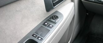
Almost all modern cars today are equipped with electric windows, which allow you to control the opening of the windows at the touch of a button. And the Russian Priors in this case are no exception. The control device, with the help of which the windows are raised and lowered, as well as many other functions, is called the Priora comfort unit. You can learn more about its structure, as well as repair, from this article.
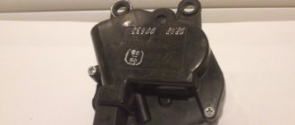
Description of the electrical package control unit
The electrical package controller in Priora is a device used to control the functionality of the vehicle. This unit is responsible for the operation of turn signals, power windows, control panel lighting, dimensions, fog lights, interior lighting, and rear window heating system. This device also ensures the normal operation of the reversing lights. The fact that the car is equipped with this device makes it even more practical.
Location
The control device on the Priora is located above the electronic engine control unit, at the bottom of the center console, in the middle. In this case, the device is connected using two connectors - power and information. The power output is used to supply voltage to the control unit, and the information output is used to perform the functions of the device. It should also be noted that the control unit is protected from external influences of dirt and moisture.
In general, this device is a circuit installed in a plastic case. The board itself includes 15 chips, each of them performing certain functions. This is the entire electrical part of the car, including power windows, door open sensors and a control system for external electric mirrors (the author of the video is the CompsMaster channel).
terms of Use
In order for the node to operate normally, certain conditions must be met:
- the air temperature level in the car interior should be from -45 to +40 degrees;
- the air humidity level in the cabin should be no more than 90%;
- The voltage parameter for normal operation should vary around 9-15 volts;
- The atmospheric pressure level should be up to 800 mm Hg.
As practice shows, malfunctions in the operation of this device often appear as a result of its overheating or disconnection of wires or contacts inside the structure. If you are faced with the problem of a device failure, first of all you need to visually diagnose it. It is quite possible that the reason can be discovered only by looking at the device.
Photo gallery “Connection diagram and designation of controller board elements”
Possible malfunctions and ways to eliminate them
What malfunctions may occur in the operation of the electrical package controller:
- Turn signal failure. First of all, you need to diagnose the serviceability of the fuse, light bulbs, and the steering column switch. It is quite possible that the contact in the switch itself is broken; the problem can be solved by resoldering the contacts or replacing it. If this does not help and the problem really lies in the board, then there are two options - either resoldering it in accordance with the diagram, or replacing it. Usually, soldering is done first, and if it does not help, then the controller itself is changed.
Video “Diagnostics of the electrical package control controller”
How to diagnose the functionality of the electrical package controller in a garage environment - see the video below (the author of the video is Vyacheslav Kravchenko).
Video “How to reprogram a standard alarm with your own hands?”
Detailed instructions for reprogramming the standard alarm are given in the video below (the author of the video is the Priorovod channel).
- We study the main malfunctions of the immobilizer
- General check before troubleshooting
- Main signs of immobilizer malfunctions
- What are the types of immobilizer malfunctions?
- How to fix immobilizer faults
Imagine a modern car without a security system thought out to the smallest detail. True, very difficult. Vehicles from the beginning of the last century immediately come to mind. But now you need to protect yourself as much as possible from intruders who are trying to steal your “pet,” even if it is in the garage.
Perhaps one of the best and most thoughtful solutions to modern car security is an immobilizer. And although repairing this device, like every complex electronic device, is not easy, it is still more reliable with it. And remember that there are specialized agencies and service centers that will help you and carry out restoration. Alternatively, you can try to troubleshoot the immobilizer yourself by first studying the instructions for it in detail.
General check before troubleshooting
Before performing general troubleshooting on your vehicle's immobilizer, check the following and correct as necessary:
— if the battery is discharged, charge it completely, and then start looking for problems with the immobilizer itself;
- if the ignition key is not original, use one approved by the brand of your car, and then start working on the immobilizer;
— remove the key and look for problems with it only;
- remove additional electronic gadgets or parts that may interfere, and look for malfunctions in the immobilizer system.
Main signs of immobilizer malfunctions
The main signs of malfunctions that should not be ignored are the following:
— when turning the key, the starter does not respond;
- when you turn the key and hear the starter moving, but the engine is silent;
— the dashboard signals with a corresponding light and sound;
— the car does not respond to pressing the corresponding button on the key fob (unless, of course, the problem is due to dead batteries in it).
Everything listed above is the most common signs that the immobilizer requires specialist help: software restoration or firmware updating. If you ignore such signals of malfunctions or entrust the task to amateurs, then everything can develop into more serious problems.
What are the types of immobilizer malfunctions?
The following types of immobilizer malfunctions are distinguished:
1. Software malfunction, which implies the destruction of the program in the engine ECU, immobilizer, or key chip. This problem can be resolved. Restoring the program of the listed systems helps. The exception is the chip key, which sometimes has no duplicates.
2. A hardware malfunction in which microcircuits fail or irregularities occur in the wiring of any system component. In this case, the fault must be diagnosed and corrected.
How to fix immobilizer faults
The immobilizer is structurally designed in such a way that a problem that occurs with one of its units will disable the entire system of the device. But of all the faults, the most common ones can be identified.
Insufficient electrical contact between the receiver and the antenna
In this case, the immobilizer malfunctions extremely often. There have been cases when it was possible to start the car only after the twentieth attempt. This problem occurs due to shaking, the antenna and receiver connectors are made poorly, the contacts are oxidized or dirt and grease have gotten on them.
In this case, the contact does not disappear immediately, but after a certain period of time, which depends on many factors. To fix this problem, you need to disconnect the receiver and antenna, turn off its power, then treat it with a special agent that eliminates contamination and oxidation. If necessary, it is better to tighten the antenna contacts.
Poor contact of one of the electrical wiring connectors
This problem also occurs if the antenna connectors are dirty. To eliminate it, dismantle all immobilizer wiring and check the condition of each wiring connector and blocks. Clean them with a special cleaner and tighten as necessary.
How to independently replace an electronic engine control unit (ECU, ECM, controller)
The electronic engine control system detects failures associated with wire breaks, short circuits to each other or to ground. With poor contact quality in the connectors. And also with a malfunction of the sensors themselves. However, there are malfunctions in the power and ignition systems that have external signs (which are noticed by the driver), but no fault codes are recorded in the memory of the electronic unit.
Main symptoms of malfunctions:
— Difficulty starting the engine.
A normal start is considered to be when the engine starts in one to three attempts. In this case, the starter should be turned on for 10 - 15 seconds, with a break between attempts of one minute. In this case, the minimum crankshaft rotation speed should be 60 - 80 revolutions per minute or one revolution per second.
If, when starting the engine, the battery voltage drops to eight volts (determined by the voltmeter on the instrument panel), then these are poor starting conditions (low ambient temperature) or the battery capacity is less than nominal. Quite often, a voltage drop is associated with oxidation of the battery terminals. Also, starting the engine will be difficult at low temperatures and high oil viscosity.
The following elements of the electronic system may be associated with the appearance of this symptom: mass air flow sensor, throttle position sensor, crankshaft position sensor, coolant temperature sensor, idle speed regulator, injector tightness, injector clogging, malfunctions in the ignition module (high-voltage wires are pierced , spark plug tips, the spark plugs themselves are faulty, the high-voltage terminals of the ignition coils are heavily oxidized). Lack of required fuel pressure due to a malfunction of the fuel pump or pressure regulator.
— jerks or failures in engine operation.
When you press the gas pedal, there is no expected acceleration. A well-warmed-up engine should, when you sharply press the gas pedal, increase the crankshaft speed from low (800-900 rpm) to high (5000 rpm) in no more than 0.75 seconds.
The following elements of the electronic system may be associated with the appearance of this symptom: mass air flow sensor, oxygen sensor, clogged injectors. This symptom can also appear when the injectors are unbalanced, there is a malfunction in the ignition module (high-voltage wires, spark plug tips are broken, the spark plugs themselves are faulty, the high-voltage terminals of the ignition coils are heavily oxidized. Lack of the required fuel pressure due to a malfunction of the fuel pump or pressure regulator.
— insufficient throttle response (power).
When the car is moving, downshifts are often used. The speed is picking up slowly. There is a feeling that the engine “does not pull, it’s dull.”
The following elements of the electronic system may be associated with the appearance of this symptom: mass air flow sensor, oxygen sensor, clogged injectors, unbalanced injectors, lack of required fuel pressure due to a malfunction of the fuel pump or pressure regulator. You should check whether the throttle valve opens fully and whether the exhaust system is clogged.
- frequent detonation.
A sharp metallic knock is heard, changing when the throttle valve is opened. The main factors contributing to the occurrence of detonation are temperature and pressure in the combustion chamber. As well as the ignition timing.
The following elements of the electronic system may be associated with the appearance of this symptom: mass air flow sensor, coolant temperature sensor, oxygen sensor, knock sensor, lack of required fuel pressure due to a malfunction of the fuel pump or pressure regulator.
The air filter should be replaced. If the filter is heavily contaminated, the correspondence between the action on the gas pedal and the signal from the mass air flow sensor sent to the control unit is disrupted.
The temperature in the combustion chamber depends on the health of the cooling system. If the engine overheats, you need to check the coolant level, the coolant pump drive belt, the operation of the electric fan of the cooling system, contamination of the radiator, the absence of vapor locks in the cooling system, and the operation of the thermostat.
— delays, twitching, failures.
This is most noticeable when starting off.
When you press the gas pedal, the engine does not immediately respond by increasing the crankshaft speed. Such delays can occur at all vehicle speeds.
Standard ignition switch - article number, price, how it works, device
The module on Priora does not work directly with the components that initiate the engine start. For it to work properly, you need to wait a few seconds before starting until the fuel pump creates the required pressure. On the Priora, only wires are connected to it - the paths along which messages pass from the ignition switch to the electronic control unit.
The ECU of the Priora car just receives data about the position of the key and can crank the starter if this operation is “not blocked”. Due to a breakdown, it can only turn on the ignition, leaving the battery to work.
After the ECU key has turned, it gives commands to several parts at once. When you turn on the second position, let the fuel pump run for 5 seconds so that it pumps fuel from the tank closer to the engine.
When the starting process itself begins, the starter rotates - the force it creates goes to the crankshaft;
the ignition system element converts the low voltage current coming from the battery into a high one so that the spark plugs are “charged” and give a spark at the right moment;
The injector creates the first batch of air-fuel mixture to put it into the chamber, where everything is ready for it - the pistons “move”, the spark plugs spark.
In the module itself, everything is simple - there is a cylinder with a return spring inside, between the coils there is a locking ball that does not allow it to curl up more than necessary, and a locking rod holds the structure in place. Finally, as a complication of the entire system, there is an “immobilizer” - an anti-theft system that you can install yourself. It just takes a long time to set it up.
A regular kit with a master key and several door cylinders (with an immobilizer) costs from 1,800 - 2,000 rubles, catalog number - 2170-3704005. A set without a master key (without an immobilizer) can be purchased for 1,200 – 1,400 rubles, article number -2170-3704006.
How to repair the electrical package control unit on a Lada Priora
"Lada Priora" drives around the city. Here is the crossroads. Required traffic light signal. And the planned turn takes place. The driver's hand habitually pressed the steering column switch. But the warning light is not blinking. From all sides there are indignant beeps and screams. Turned without signaling! The driver embarrassedly presses the hazard warning button to stop and investigate. However, there is no response here either. Yeah! It's probably the turn signal relay! It needs to be changed, that's all! Fortunately, auto parts stores are everywhere now. But here, too, not everything is so simple. It seems that the “electrical package” or, as it is also called, the Priora comfort unit, has failed.
The main functions performed by the electrical package control unit (comfort unit)
In fact, this device is a multifunctional control computer. His responsibilities include ensuring the functionality of many Priora functions:
- Electric windows.
- Adjusting the side mirrors.
- Turn and hazard warning lights.
- Anti-theft system.
- Door locking from the driver's door remote control.
- Lighting module.
So many options require precise operation of the Priora comfort controller.
Location of the comfort controller in the cabin
You need to know that there are two options for the location of this device:
- On the first Priora models it is under the beard.
- On subsequent ones, to the left of the mounting block.
When these cars appeared, the comfort unit was installed in the area of the electronic control unit. That is, under the “beard”. If you open the decorative plastic cover located at the passenger’s left foot, you will see the Priora control unit with attached relays. Directly above them is a comfort unit (electrical package).
On subsequent cars this unit was positioned slightly differently. At the driver's left foot, with the instrument panel cover removed under the steering wheel, there is a fuse and relay assembly. Or - a mounting block. And behind it, at the wall of the body, the electrical package is mounted. Access to it is quite difficult.
Removing the comfort block on new models
If you follow the manufacturer's technological instructions, this is a very complex and time-consuming process. Suffice it to say that according to this scheme it is necessary to partially dismantle the entire dashboard of the Priora. Of course, experienced locksmiths do not do this. The process goes as follows. The negative terminal of the battery is removed.
Attention! This must be done during any work related to the electrical equipment of the car. And especially those that are controlled by a computer
After this, remove the decorative panel under the steering wheel. It is secured at the bottom with 3 plastic swivel fasteners. The mounting block will become available. Now comes the most difficult part. You will need a 10mm bell key. This is the most convenient option for this job.
You'll have to climb and grope with your hand. As already mentioned, the electrical package controller is screwed behind the mounting one. It is perpendicular to it. It is secured with two bolts
heads 10. Before unscrewing them, you need to disconnect the three wiring harnesses connected to the block. It is not difficult. And it is impossible to confuse them during installation. They have different entry options. After this, you can remove the mounting bolts. Since the ears on the device are not closed, but have a free exit, one of the bolts can only be loosened 3-4 turns. And then take out the block.
Important! The knot comes out only in one position, and if you couldn’t pull it out right away, don’t panic. Just turn it gradually to remove
Install the new one in the same way.
Replacement on the first Priors
This is generally a simple operation. The shield is removed from the bottom of the “torpedo” on the passenger side. The comfort controller is perfectly accessible. Unscrew the fasteners in the same way and remove the device. Replace with new one. The only thing is that the wiring harnesses are on the driver's side. But it is just as easy to remove the side panel, which is secured with 1 bolt.
About the repair of the comfort unit
This is a very tricky issue. It’s worth clarifying right away that an ordinary car enthusiast has no business even trying to do this. For such an operation, you need to have at least a professional kit for soldering microcircuits on hand. Or better yet, a soldering station. No service station will undertake this work. So it’s easier to replace the failed unit with a new one.
In the video below, a specialist checks the serviceability of the Priora comfort unit.
How to activate the immobilizer?
Before starting use, it is recommended to activate the immobilizer.
In order to do this, you must follow these instructions:
- Take both standard keys, get behind the wheel and close the door behind you.
- Insert the key with the red mark (training) into the lock and turn on the ignition.
- After six seconds, turn off the ignition system. The indicator lamp in the instrument cluster will flash approximately 5 times per second, which is a sign of a normal learning process. If this does not happen, there may be problems with the immobilizer system or faulty components.
- While the warning light is flashing, you must remove the red key, insert a regular key into the lock and activate the ignition. This procedure should be completed within six seconds. The buzzer will confirm that the training has been completed correctly with three short beeps.
- Wait another six seconds, after which the buzzer should sound two additional signals. If this does not happen and the warning light stops flashing rapidly, then the learning process has failed and should be started again. If re-learning is also unsuccessful, then you should look for a malfunction in the system or key, which could have been previously trained for a different immobilizer.
- If training is successful, turn off the ignition. If it is necessary to train additional keys, then such actions are performed with each one.
- If you do not need to register additional keys, then immediately after the sound signals you must turn off the ignition and remove the regular key and replace it with a red one.
- Turn on the ignition and receive confirmation in the form of three beeps with the buzzer.
- In six seconds, two more signals should pass. After this, you can turn off the ignition, but do not remove the key from the lock.
- Six seconds after turning off the ignition circuits, the buzzer should sound once and the flashing frequency of the lamp should increase.
- After this, turn on the ignition (within 5...6 seconds) using the red key and turn it off after three seconds.
- After a few seconds, the buzzer should sound (three beeps) and the lamp on the instrument cluster should go out. The ignition can be turned on again no earlier than after 10 seconds. When using some controllers, sound signals may appear immediately when the ignition is turned off.
How to replace the Priora ECU
There can be many reasons for replacing the controller: the desire to install another model that can work with more efficient firmware, failure, incorrect operation.
You can find out which ECU is on the Priora using the diagnostic method, or by using the firmware identifier, which can be checked on a special website. Bosch M 10 and “January-7” controllers are installed on cars.
In order to change the ECU, you need to do the following:
- Disconnect the on-board system from the battery. To do this, simply remove the negative terminal.
- Remove the plastic lining of the tunnel on the right side.
- Push the bracket securing the connector with the bundle of wires all the way.
- Remove the block with wires.
- Unscrew the 2 nuts in the place where the Priora ECU is attached to the bracket.
- Lift the controller up and remove it through the right side.
As can be seen from the description, the procedure is very simple and does not take more than 5-10 minutes. Installation occurs in reverse order.
What functions does the block provide?
- fog lights, low beam, side lights;
- lighting in the car interior;
- direction indicators;
- power window system;
- operation, adjustment and heating of side mirrors;
- anti-theft system;
- signaling;
- door locking;
- trunk lighting;
- instrument panel lighting.
Partial, and even more so complete failure of the unit causes significant trouble for any car owner. The biggest problems are caused by the failure of the comfort unit in dense city traffic conditions.
Types of ECU (esud, controller). What kind of ECUs are installed on VAZ?
"January-4", "GM-09"
The very first controllers on SAMARA were January-4, GM - 09. They were installed on the first models before the year 2000. These models were produced both with and without a resonant knock sensor.
The table contains two columns: 1st column – ECU number, second column – brand of “brains”, firmware version, toxicity standard, distinctive features.
| 2111-1411020-22 | January-4, without DC, RSO (resistor), 1st ser. version |
| 2111-1411020-22 | January-4, without recreation center, RSO, 2nd ser. version |
| 2111-1411020-22 | January-4, without recreation center, RSO, 3rd ser. version |
| 2111-1411020-22 | January-4, without recreation center, RSO, 4th ser. version |
| 2111-1411020-20 | GM,GM EFI-4,2111,with DC,USA-83 |
| 2111-1411020-21 | GM, GM EFI-4, 2111, with DC, EURO-2 |
| 2111-1411020-10 | GM,GM EFI-4 2111,with DC |
| 2111-1411020-20 h | GM, RSO |
VAZ 2113-2115 from 2003 are equipped with the following types of ECUs:
"January 5.1.x"
The following types of hardware implementation are distinguished:
- simultaneous injection;
- in pairs - parallel injection;
- phased injection.
Interchangeable with “VS (Itelma) 5.1”, “Bosch M1.5.4”
| 2111-1411020-71 | January-5.1.1, without dk, with |
| 2111-1411020-71 | January-5.1.1, without dk, with |
| 2111-1411020-71 | January-5.1.1, without dk, with |
| 2111-1411020-71 | January-5.1.1, without dk, with |
| 2111-1411020-71 | January-5.1.1, without dk, with |
| 2111-1411020-72 | Itelma, without dk, with |
| 2111-1411020-72 | Itelma, without dk, with |
| 2111-1411020-72 | Itelma, without dk, with |
| 2111-1411020-72 | Itelma, without dk, with |
"Bosch M1.5.4"
The following types of hardware implementation are distinguished:
- simultaneous injection;
- in pairs - parallel injection;
- phased injection.
Interchangeable with “VS 5.1”, “January 5.1.x”.
| 2111-1411020 | without dk, rso |
| 2111-1411020 | without DC, with (adjustable with scanner) |
| 2111-1411020-70 | BOSCH, without dc, with |
| 2111-1411020-70 | BOSCH, without dc, with |
"Bosch MP7.0"
As a rule, this type of controller is released onto the market and installed at the factory in a single volume. Has a standard 55-pin connector. Capable of working with recrossing on other types of ECM.
"Bosch M7.9.7"
These brains began to be part of the car at the end of 2003. This controller has its own connector, which is incompatible with connectors produced before this model. This type of ECU is installed on VAZ with EURO-2 and EURO-3 toxicity standards. This ECM is lighter weight and smaller in size than previous models. There is also a more reliable connector with increased reliability. They include a switch, which will generally increase the reliability of the controller.
This ECU is in no way compatible with previous controllers.
"VS 5.1"
The following types of hardware implementation are distinguished:
- simultaneous injection;
- in pairs - parallel injection;
- phased injection.
"VS 5.1" is interchangeable with "Bosch M1.5.4", "January 5.1.x".
"January 7.2."
This type of ECU is made with a different type of wiring (81 pins) and is similar to Boshevsky 7.9.7+. This type of ECU is produced both by Itelma and Avtel. Interchangeable with Bosch M.7.9.7. As for the software, 7.2 is a continuation of January 5th.
This table shows variations of the BOSCH ECU, 7.9.7, January 7.2, Itelma, installed exclusively on the VAZ 2109-2115 with a 1.5L 8kL engine.
Chip tuning LADA Priora in Nizhny Tagil
LADA Priora Chip tuning LADA Priora allows you to increase the dynamic characteristics of the engine without interfering with the engine design and replacing parts, by flashing the ECU and changing the engine control program. Chip tuning is safe and does not reduce the life of the engine and transmission. Each tuning firmware that we install on LADA Priora is commercial, that is, purchased by us from the best tuning studios in Russia. Here are some famous authors with whom we work: Paulus, Ledakol, Adakt, Motor-master.
With flashing it is possible to:
- Increase the power of a gasoline engine up to +10% hp.
- Increase diesel engine torque up to +10% HP
- Reduce accelerator pedal response time
- Disable software control of the catalyst and lambda probe after it
- Disable programmatically the first lambda probe (EURO-0)
- Disable the Absorber valve software
- Make individual adjustments
- and more... (check with a specialist)
Price list for chip tuning LADA Priora
| Model | ECU | Price |
| LADA Priora (2008-2010) | January 7.2, Bosch 797, Itelma M73 | 1,800 rub. |
| LADA Priora (2008-2010) | Avtel M73 (write protected) | 2,500 rub. |
| LADA Priora (2010-2014) | Avtel/Itelma M74, Bosch 17.9.7 | 2,500 rub. |
| LADA Priora (2013-present) | Avtel/Itelma M74.5, M75 | 3,000 rub. |
Computer diagnostics of the engine for errors is included in the cost of work. The prices indicated in the catalog may vary both up and down; check with a specialist for all the details by contacting us by phone or via social networks.
Didn't find your car? Contact us, I'm sure we can help you!
Why choose us?
- Our auto repair shop has been professionally engaged in flashing and chip tuning of cars for more than 6 years. The experience we have accumulated allows us to offer chip tuning for a large number of brands and models of cars. The experience of our work can be easily tracked in our group on VKontakte in which we regularly post photo reports of the work done, our experience and achievements. Car owners who have done chip tuning with us leave their reviews and tell us what has changed after the firmware.
- We use high-quality software from the best authors, such as Paulus, Ledakol, Adakt. We work with leading tuning studios in Russia and Europe, such as LabSpeed (St. Petersburg), SEDOX (Norway), ChipAuto (Latvia) and others...
- Our experience in optimizing engine control programs guarantees you that chip tuning will not affect the life of the engine and gearbox. All settings are within safe parameters, and you can be sure that our work will not harm the car.
- To reprogram electronic control units, we use only original equipment of Russian and European production: - Kess v2 Master and K-Tag Master from Alientech (Italy) - PCM Flasher, MMC Flasher, Combiloader (Russia) The amount of equipment allows us to offer our services on a wide range brands and models of cars. Most cars have the ability to reprogram via the OBD2 service diagnostic connector
- All the firmware we work with is configured based on the factory firmware, preserving all identifiers visible to the official dealer, so with us you don’t have to worry about the car being removed from warranty after our work.
- We are confident in ourselves and give a guarantee, money back and factory program, if you are not satisfied with the result of our work!
Comments
You can ask a question here that interests you, write your review or opinion. We will try to answer you as soon as possible.
Self-diagnosis systems
Like any computer, the Priora ECU has feedback from the user.
The driver learns about problems using signal codes, which can be seen in two ways: using an additional on-board computer connected to the diagnostic connector, and on the instrument panel after performing simple manipulations.
For self-diagnosis, you can install the following devices:
- State X 1 P Priora. A small device that is inserted in place of a standard button. Has an LED display with 3 characters. In addition to the diagnostic function using 30 parameters, it allows you to warm up the spark plugs during cold periods, independently regulate the temperature at which the cooling system fan turns on, and reset engine errors.
- Priora State Matrix. A more serious on-board computer. It is placed in place of the standard clock and has a graphic display of 128 x 32 pixels.
In addition to the functions listed on the previous computer, the device can work with gas equipment, reading gas consumption. The “Afterburner” function allows you not only to reset engine errors, but also to roll back the controller to its factory state, thereby resuscitating it. After activating this option, the “Priors” ECU mode will turn on, which was set at the factory. This bookmaker also has the ability to update the software.
Multitronics C-900. Universal on-board computer. Can be installed in different places. It has enormous capabilities both in diagnostics and adjustments. Suitable for a wide range of cars. It has a 480 x 800 pixel LCD display and the ability to change settings directly from your home PC.
ECU "Priors": characteristics, photo, where it is located
The engine operation of the VAZ-2170 Priora is controlled using an electronic control unit (ECU). It also monitors compliance with environmental safety standards “Euro 3”, “Euro 4” and provides feedback using the OBD-II diagnostic connector.
What data goes to the controller
The Priora ECU operates in the mode of continuous reading of information from sensors. Based on this information, the computer makes decisions about changing the operating modes of the engine systems. The types of data entering the controller are as follows:
- electrical voltage in the car network;
- presence of detonation in combustion chambers;
- vehicle speed;
- cooling system temperature;
- amount of oxygen in exhaust gases;
- air flow;
- temperature of the air entering the intake manifold;
- position of the camshaft and crankshaft;
- throttle position.
How to perform diagnostics using a standard on-board computer
In the absence of additional diagnostic tools, errors that are read by the Priora ECU can be displayed on the instrument panel in the standard way. To do this you need:
- While holding the mileage reset button, turn on the ignition. After pressing for 4 seconds, the instrument panel begins to move (all indicators light up, instrument arrows rotate around the axis several times, the LCD display turns on all registers). This indicates that the self-diagnosis mode has turned on.
- On the right steering column switch, the Reset button selects the position for displaying the firmware version, error code, and error reset.
If you need to get rid of an engine error, in reset mode, press Reset and hold the button in this position for 3 seconds.
Error codes
In error mode, the computer may display the following codes:
- 2 - the network voltage is too high;
- 3 — malfunction of the fuel level sensor;
- 4 — malfunction of the coolant temperature sensor;
- 5 — outside temperature sensor error;
- 6 - engine temperature is too high;
- 7 - low pressure in the lubrication system;
- 8 — malfunction of the brake system;
- 9 - low battery voltage.
After troubleshooting, you need to reset the error. If no action is performed within 20 seconds, the on-board computer goes into normal operation.
Interpretation of the symbols for the rear wiring harness of the VAZ Priora
This part is organized to supply power to the main instruments and engine control system of the Lada Priora. From here, voltage is supplied to the main components, units of the vehicle’s power plant, as well as control sensors and ECUs. The standard electrical circuit connection system (pinout) looks like this:
- 1 – ECU power supply;
- 2 – main block of the electronic system to the dashboard;
- 3 – distribution board;
- 4 – speedometer;
- 5 – road surface roughness sensor;
- 6 – indication of pressure in the engine crankcase;
- 7 – TPS;
- 8 – DTOZH;
- 9 – indication of antifreeze temperature sensor;
- 10 – mass air flow sensor;
- 11 – control XX;
- 12 – main relay of the fuel pump;
- 13 – VT circuit fuse;
- 14 – relay BZ;
- 15 – fuse of the above circuit;
- 16 – ECU fusible link;
- 17 – DPKV;
- 18 – power supply for mass air flow sensor;
- 19 – phase distribution;
- 20 – mixture detonation sensor;
- 21 – EMC for purging the adsorber;
- 22 – diagnostics of the air flow sensor;
- 23 – power supply to the ignition coil;
- 24 – supply voltage to spark plugs;
- 25 – power supply to fuel injectors;
- 26 – terminal from the ignition coils to the ECM;
- 27 – feedback from 26;
- 28 – ECM connector to the injection system;
- 29 – response to the previous output;
- A – phase on the battery;
- B1/2 – ignition mass;
- C1 – mass from short circuit.
The rear part of the electrical wiring chain is responsible for the vehicle's lighting and peripheral systems. This includes lights, locks and windows. The pinout of tips and terminals looks like this:
- 1 – dashboard response;
- 2 – power supply for the door behind the driver;
- 3/28 – power supply for the front passenger panel equipment;
- 4 – maintenance of power windows and door locks;
- 5-6 turn signals;
- 7 – interior lighting;
- 8 – handbrake indication switch;
- 9-10 – aft dimensions;
- 11 – temperature inside the car;
- 12-15 – circuit breakers for lighting the interior of the machine;
- 16/17 – power supply to the devices of the aft right and front left doors, respectively;
- 18/19 – voltage to the rear right and left speakers, respectively;
- 20 – cigarette lighter power core;
- 21 – EBN;
- 22 – contact group of the cargo compartment lighting circuit breaker;
- 23 – heated rear windshield;
- 24 – luggage compartment lighting lamp;
- 25 – additional stop;
- 26 – power line to the electric lock of the luggage compartment lid;
- 27 – power supply for rear number plate illumination;
- A1-4 – mass;
- ХР1/3 – electrical package power controller.
The small harness, located in the luggage compartment, has only three terminals:
- 1 – power supply to the stern license plate lights;
- 2-3 – license plate lighting lamps;
- 4 – trunk lid lock motor.
The harness is routed to supply power to the driver's door equipment. There is an output to the key panel installed in the armrest. There are six elements in total:
- 1 – additional terminal to the rear of the machine;
- 2 – line to the left fuse;
- 3 – electric window drive;
- 4 – armrest control module;
- 5 – door lock drive;
- 6 – rear view mirror control chip.
The unit duplicates the voltage supply from the center console to the passenger keypad located on the right side of the car. There are only seven connectors here:
- 1 – continuation of the main highway to the rear;
- 2 – terminal of the line to the right front speaker;
- 3 – window lift drive;
- 4 – electric window lift button;
- 5 – door lock drive;
- 6 – control of the position of the rear view mirror, as well as heated glass;
- 7 – continuation of the highway to the rear.
Read more: Connecting a Pioneer radio by wire colors, diagram and video instructions
Lada Priora Sedan 2007, 107 l. With. - with your own hands
Lada Priora, 2009
Comments 38
I would like a diode bridge right now and a snout for 350 rubles... Fucking dreams
The diode bridge that was purchased is from the so-called Chevrolet Niva with a voltage regulator from the 10, it does not work, but if you buy an additional regulator from Shnivy, the generator would work a little better, the power will not increase, but the voltage will be more stable
I've been having the same problem lately. The generator produces 13 V and, accordingly, the battery is constantly undercharged and the light flickers at idle. And a couple of days ago the revolutions jumped to 2000 rpm. We need to start doing something.
Advice! Install a (THREE LEVEL VOLTAGE REGULATOR) on your generator and you WILL FORGET ABOUT UNDERCHARGING the generator FOREVER! There is information on the Internet about this gadget. I suffered with undercharging for four years. And now I’ve been using this gadget for six years now, which has never failed!
Tell me, is there a Bosh 14v regulator, can it give more than 14v, otherwise I checked it at work and it cuts off at 13.8, everyone claims that it should cut off at 14.3, how can it be if the limit is 14v? very interesting, please tell me