Volkswagen Golf 2
generation was produced with sedan and hatchback bodies not only in Germany, but also in the UK, Finland, Japan, the USA and some other countries of the current European Union. Years of production: 1983, 1984, 1985, 1986, 1987, 1988, 1989, 1990, 1991 and 1992. The model underwent the most significant restyling in 1987. More than 6.3 million cars were produced on all continents. In this article you will find a description of the fuse and relay blocks of the 2nd generation Volkswagen Golf, with photo examples of blocks, their diagrams and designations of elements. Note the fuse responsible for the cigarette lighter. In conclusion, we will offer for download a book with a complete description of electrical circuits.
The number of elements in the main unit may differ from those shown and depends on the configuration, year of manufacture and country of delivery. The current purpose specifically for your car will be printed on top of the protective cover - the box. And if the generation is not suitable, study the description for the 3rd. We also note that the current schemes are suitable for the Jetta 2 model.
Location and layout
Let's look at the diagrams and location of the power supply in Volkswagen Golf cars of the second, third, fourth, fifth and sixth generations. In all cases, the device is located on the driver's side under the instrument panel. The only difference is that in models of the second and third generations the power supply is located on a shelf under the steering wheel. And in models of the fourth, fifth and sixth generations - directly in the dashboard on the side where the driver's door comes into contact with the panel.
Volkswagen Golf 2
The location of the block in this vehicle model is on the left side in the area of the driver’s seat under the dashboard. We invite you to familiarize yourself with the diagram and decoding of the power supply components.
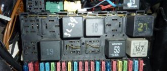
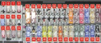
Fuse box FV Golf second generation
| Number | Purpose |
| 1, 2 | These power supply components are responsible for the functionality of the left and right low beam headlights. |
| 3 | This fuse ensures the operation of the instrument panel lighting and lamps that illuminate the license plate of the car. |
| 4 | This component ensures the functioning of the glove compartment lighting bulbs. |
| 5 | Responsible for the operation of the windshield wiper and washer motor. |
| 6 | Guarantees the operation of the interior heater fan. |
| 7 | Responsible for the operation of the right rear headlight and brake lights. |
| 8 | Provides heated rear window. |
| 9 | Fog lights. |
| 10,11 | Responsible for the performance of high beam lights. |
| 12 | Steering horn. |
| 13 | Provides functionality for rear position lights. |
| 14 | Determines the functionality of the fuel shut-off valve. |
| 15 | If this element fails, the operation of the instrument panel may be disrupted. |
| 16 | Guarantees the functionality of the alarm system. |
| 18 | If this element fails, the operation of the radiator fan and air conditioner is impossible. |
| 19 | Responsible for brake lights. |
| 20 | Car interior lighting. |
| 21 | Guarantees the operation of the multimedia system or radio, as well as the cigarette lighter. |
Fuses numbered 17 and 22 are spare.
Volkswagen Golf 3
The power supply circuit on this vehicle model is similar to the power supply installed in the second version of the car, but there are some differences. Therefore, we will consider the circuits and purpose of power supply elements separately. Location: on the dashboard on the left side, on the shelf under the steering wheel.
Diagram of the power supply installed in Volkswagen of the third version
| Number | Purpose |
| 1, 2 | Low beam lamps, left and right. |
| 3 | Car license plate lights. |
| 4,5 | Responsible for the operation of the windshield and rear window washer and wiper motors. |
| 6 | Guarantees the functionality of the heating element of the heating system. |
| 7,8 | If this component fails, the vehicle's rear and front side lamps will not work. |
| 9 | Rear window heating device. |
| 10 | Guarantees the functionality of the fog lights. |
| 11,12 | Responsible for the functionality of the left and right high beam lamps. |
| 13 | Steering horn. |
| 14 | If this component breaks down, the reversing lamps will stop working, as well as the washer nozzle heating device. |
| 15 | Responsible for the functionality of the gasoline shut-off valve, as well as the speedometer drive sensor. |
| 16 | If this element breaks down, malfunctions or inaccuracies in the operation of the instrument panel may occur. |
| 17 | Functioning of turn signal lamps and hazard warning lights. |
| 18 | If this fuse is blown, the car will not start because this component ensures the operation of the fuel pump. |
| 19 | Air conditioning and radiator cooling fan. |
| 20 | Lamp lights that turn on when you press the brake pedal. |
| 21 | Guarantees the functionality of car interior lighting bulbs, electronic clocks, and luggage compartment lighting. |
| 22 | Responsible for the operation of the multimedia system or car radio, as well as the cigarette lighter. |
Volkswagen Golf 4
Below is a diagram and purpose of power supply devices for the fourth version of PV. The block itself is located on the left side of the dashboard, near the driver's seat. To access it and see it in person, you need to remove the cover using a slotted screwdriver.
Volkswagen Golf 5, 6
For models of the fifth and sixth versions, the power supply circuit will be the same. The location of the power supply is on the left side of the instrument panel, in the area where the driver's door comes into contact with the dashboard. Below is a diagram and description of all components.
Features of replacing fuses in Golf 2
Procedure
To replace an element in the fuse box in a Golf 2, you must follow the following procedure:
- Remove the cover from the block.
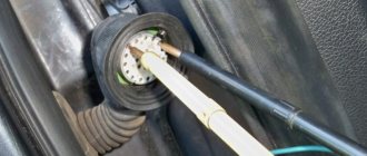
- Identify the faulty element by the melted walls and remove it using plastic tweezers.
- Insert a new part in accordance with the pinout of the fuse box in Golf 2. The fuse must be designed for the same amperage, which can be determined by the color and special inscription on the holder.
- Close the block with a lid.
You cannot replace a damaged element with wire or other improvised materials. This may result in equipment failure or even a fire in the unit. For safety reasons, it is best to keep a small set of spare fuses in your car at all times. For this purpose, special fastenings are provided in the block.
Appearance of fuses in Volkswagen Golf 2
Recommendations
Recommendations for replacement:
- Before starting work, it is advisable to turn off the electrical circuit in which the fuse has failed.
- It is not recommended to use grips that are too hard as they can scratch the contacts.
- If a constantly blowing fuse controls the operation of several circuits, you need to alternately connect one circuit to it and check it for errors. Only in this case will it be possible to find the true cause of the malfunction.
- Using a fuse with a higher amperage may cause damage or fire.
Price
dealersauto partsdisassembly
Using the description of the fuse box in Golf 2, the user can easily carry out the replacement himself. But in some cases it is better to contact a service center. For example, replacing a heater fuse on a Golf 2 costs from 300 rubles. If during the diagnostic process any other problems were identified, the price for eliminating them will be higher.
Fuses in a car play a vital role, ensuring the stable operation of all components and the safety of the driver. Timely replacement of faulty elements increases the chances of long-term use of the car without serious breakdowns.
The location of the fuse box in Golf 2 is shown in this video:
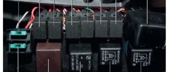
Fuse and relay box in the cabin
The interior fuse box in the Volkswagen Golf III is located near the pedal assembly and is covered with a decorative cover.
Location of the unit in the cabin
The schematic diagram and explanation are given below.
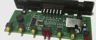
Appearance
Fuse and relay layout
Relay
Diagram number Switched circuit
| 1 | Air conditioner |
| 2 | Rear window wiper/washer |
| 3 | ECU |
| 4 | Main ignition circuits |
| 5 | — |
| 6 | Turn signal switch |
| 7 | headlight washer |
| 8 | Windshield wiper/washer intermittent relay |
| 9 | Seat belt indicator 1995 |
| 10 | PTF |
| 11 | Sound signal |
| 12 | Fuel pump |
| 13 | Intake manifold heater |
| 14 | — |
| 15 | ABC pump |
| 16 | Reversing lights (Ecomatic) |
| 17 | High beam (Ecomatic) |
| 18 | Low beam (Ecomatic) |
| 19 | Fuse (30A - air conditioning, Climatronic 2.0/2.8 (1993) |
| 20 | Start inhibit switch |
| 21 | Oxygen sensor |
| 22 | Seat belt indicator (1995) |
| 23 | Vacuum pump (Ecomatic) |
| 24 | Thermal fuse - Power windows |
Circuit breakers
Number on the diagram Rating Protected circuit/consumer
| F1 | 10 | Low beam: left side |
| F2 | 10 | Low beam: right side |
| F3 | 10 | License plate lamps |
| F4 | 15 | Tailgate glass cleaner and washer |
| F5 | 15 | Cleaners, headlight washers |
| F6 | 20 | Heater fan |
| F7 | 10 | Front and rear dimensions - right |
| F8 | 10 | Front and rear dimensions - left |
| F9 | 20 | Rear window defroster |
| F10 | 15 | PTF |
| F11 | 10 | High beam: left side |
| F12 | 10 | High beam: right side |
| F13 | 10 | Sound signals |
| F14 | 10 | Reversing lights, washer nozzle heaters, central locking, electric door mirrors, heated seats, cruise control, electric windows |
| F15 | 10 | Speedometer, intake manifold heater |
| F16 | 15 | Instrument cluster lights, ABS indicator, SRS indicator, sunroof, Thermotronic heating system |
| F17 | 10 | Hazard warning lamps, direction indicators |
| F18 | 20 | Fuel pump, heated oxygen sensor |
| F19 | 30 | Radiator fan, air conditioning relay |
| F20 | 10 | Brake lights |
| F21 | 15 | Interior, trunk, central locking, sunroof lamps |
| F22 | 10 | Radio, cigarette lighter |
Removal and replacement
The replacement process is identical for all versions of the FV. To replace, you will need a screwdriver or wrenches, depending on whether the power supply is attached to the body with bolts or self-tapping screws. Decide which tool you need, and you can start removing.
- Using a screwdriver, disconnect the dashboard trim behind which the power supply is installed in your car.
- Unscrew the screws securing the power supply to the car body.
- Pull out the device: it will hang on the wires.
- Take the new power supply unit and, one by one, disconnecting it from the old device, insert all the necessary wires into the connectors of the new power supply unit.
- Install the new power supply in place by tightening the fastening screws and closing the instrument panel trim.
Replacing fuses in the interior module
For ease of checking and replacing fusible elements in the 3rd generation VolksWagen Golf, produced from 1991 to 1998, they are located in a common block. It is located on the driver's side at the bottom of the instrument panel and is closed with a non-sealed lid. To access the fuses, you need to tighten the two latches and remove the cover down.
After this, it is recommended to disconnect the positive terminal of the battery.
Checking the integrity of fuses can be done in two ways:
- Visual inspection - if the fuse element has visible damage, the PP has failed.
- Measurement with a multimeter - ringing the fuse contacts will show its functionality.
The failed element must be replaced with a fuse of the same rating. Failure to comply with this rule may damage the protected circuit or cause the wiring to melt.
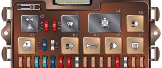
Pinout of the PP module and Golf 3 relay
On the cover of the interior fuse and relay module there is a diagram of the designations of the protected elements. A special connector contains a tool for replacing fusible elements and spare fuses.
Deciphering the interior fuse module diagram for Volkswagen Golf 3
Protected electrical circuit or device Rating, АColor No.
| A/C compressor, relay | 1 | ||
| Rear view wiper, rear view washer, relay | 2 | ||
| ECU, Main Engine Control Unit, Main Relay | 3 | ||
| Electronic ignition system, relay | 4 | ||
| Reserve connector | 5 | ||
| Front and rear turn signal light breaker, relay | 6 | ||
| Headlamp washer motor controller, relay | 7 | ||
| Windshield wiper mode controller, windshield washer mode controller, relay | 8 | ||
| Front passenger seat belt buzzer, used on vehicles manufactured after 1995, relay | 9 | ||
| Front fog lights, relay | 10 | ||
| Two-tone horn, relay | 11 | ||
| +12V power supply for fuel pump, relay | 12 | ||
| Air heating in the intake manifold, relay | 13 | ||
| Reserve connector, relay | 14 | ||
| ABS hydraulic unit motor, relay | 15 | ||
| Reverse gear light, relay | 16 | ||
| Head optics, low beam bulbs, relay | 17 | ||
| Head optics, high beam bulbs, relays | 18 | ||
| Power fuse for the air conditioning compressor on cars with climate control, after 1993, with 2.0 l and 2.8 l engines | 19 | ||
| Unauthorized engine start attempt interrupter, relay | 20 | ||
| Exhaust gas oxygen sensor, heating coil relay | 21 | ||
| Front passenger seat belt buzzer, used on cars produced before 1995, relay | 22 | ||
| Vacuum brake booster, relay | 23 | ||
| Thermal fuse for power window motor | 24 | ||
| Right headlight, low beam bulb, electric motor for headlight height adjustment | 10 | Red | F1 |
| Left headlight, low beam bulb | 10 | Red | F2 |
| Rear license plate lamps | 10 | Red | F3 |
| Rear window wiper, rear view window washer motor | 15 | Blue | F4 |
| Windshield wipers, windshield washer motor, headlight washer motor | 15 | Blue | F5 |
| Electric motor of the main interior heater | 20 | Yellow | F6 |
| Left side, parking light bulbs, front and rear | 10 | Red | F7 |
| Right side, parking light bulbs, front and rear | 10 | Red | F8 |
| Heated rear view glass | 20 | Yellow | F9 |
| Front fog light bulbs | 15 | Blue | F10 |
| Right headlight, high beam bulb | 10 | Red | F11 |
| Left headlight, high beam bulb | 10 | Red | F12 |
| Two-tone buzzer in the cabin | 10 | Red | F13 |
| Complex fuse: | 10 | Red | F14 |
| side window drive motor; | |||
| reverse gear light bulbs; | |||
| cruise control system; | |||
| heated windshield washer jets; | |||
| heated front car seats; | |||
| central locking system; | |||
| adjusting the exterior rearview mirrors | |||
| Additional heating of air in the intake manifold, vehicle speed measuring device | 10 | Red | F15 |
| Thermotronic additional heating system, electric sunroof, AirBag system indicator, ABS system indicator, main instrument panel lighting | 15 | Blue | F16 |
| Hazard warning button, front and rear turn signal lights | 10 | Red | F17 |
| +12V oxygen sensor power supply, fuel pump power supply | 20 | Yellow | F18 |
| Engine cooling radiator fan motor, air conditioning compressor, relay | 30 | Green | F19 |
| Brake light bulbs in rear lights | 10 | Red | F20 |
| Central locking, power sunroof drive, interior lighting, luggage compartment lighting | 15 | Blue | F21 |
| Car radio, active radio antenna, cigarette lighter socket | 10 | Red | F22 |
Underhood fuse module
To access the motor fuse and relay module, you need to move the fixing elements of the cover in the direction of travel of the car and remove it. After checking and replacing the PP, it is necessary to replace the cover, return the latches to their original position and make sure that the unit is sealed.
Layout of fusible elements in the motor module.
| Circuit or electrical equipment being protected | Denomination, A | Color coding | № |
| Connector not used | 1 | ||
| Steering Column Switches | 5 | Light yellow | 2 |
| OBDII connector for diagnostics | 5 | Light yellow | 3 |
| ABS system unit, electronic components | 30 | Light green | 4 |
| Automatic transmission controller | 15 | Blue | 5 |
| Instruments on the panel | 5 | Light yellow | 6 |
| Connector not used | 7 | ||
| Radio in the center console | 15 | Blue | 8 |
| GSM phone | 5 | Light yellow | 9 |
| Engine controller, relay | 5 | Light yellow | 10 |
| Cabin heater fan controller, auxiliary heater controller | 20 | Yellow | 11 |
| OBDII diagnostic bus controller | 5 | Light yellow | 12 |
| ECU, engine controller | 15 | Blue | 13 |
| Relay +12V on-board power supply | 20 | Yellow | 14 |
| Exhaust oxygen sensor, fuel pump, glow plugs diesel internal combustion engine | 15 | Blue | 15 |
| ABS system unit, electronic components | 30 | Light green | 16 |
| Klaxon | 15 | Blue | 17 |
| Standard audio amplifier | 30 | Light green | 18 |
| Front windshield wipers | 30 | Light green | 19 |
| Connector not used | 20 | ||
| +12V lambda probe heating | 15 | Blue | 21 |
| Brake pedal breaker, clutch pedal breaker | 5 | Light yellow | 22 |
| Intake Manifold Air Recirculation Pump, High Pressure Fuel Pump, Mass Air Flow Sensor (MAF) | 10 | Red | 23 |
| EGR valve | 10 | Red | 24 |
| Front headlight, right side | 30 | Light green | 25 |
| Front headlight, left side | 30 | Light green | 26 |
| Intake manifold air recirculation pump, engine warm-up mode | 40 | Orange | 27 |
| Engine starter relay | 40 | Orange | 28 |
| +12V on pin 30 | 40 | Orange | 29 |
| Contact X | 40 | Orange | 30 |
| Auxiliary cooling fan motor relay | R1 | ||
| Automatic transmission controller relay | R2 |
Pinout of the PP module and Golf 3 relay
On the cover of the interior fuse and relay module there is a diagram of the designations of the protected elements. A special connector contains a tool for replacing fusible elements and spare fuses.
Deciphering the interior fuse module diagram for Volkswagen Golf 3
Protected electrical circuit or deviceRating, АColor No.
| A/C compressor, relay | 1 | ||
| Rear view wiper, rear view washer, relay | 2 | ||
| ECU, Main Engine Control Unit, Main Relay | 3 | ||
| Electronic ignition system, relay | 4 | ||
| Reserve connector | 5 | ||
| Front and rear turn signal light breaker, relay | 6 | ||
| Headlamp washer motor controller, relay | 7 | ||
| Windshield wiper mode controller, windshield washer mode controller, relay | 8 | ||
| Front passenger seat belt buzzer, used on vehicles manufactured after 1995, relay | 9 | ||
| Front fog lights, relay | 10 | ||
| Two-tone horn, relay | 11 | ||
| +12V power supply for fuel pump, relay | 12 | ||
| Air heating in the intake manifold, relay | 13 | ||
| Reserve connector, relay | 14 | ||
| ABS hydraulic unit motor, relay | 15 | ||
| Reverse gear light, relay | 16 | ||
| Head optics, low beam bulbs, relay | 17 | ||
| Head optics, high beam bulbs, relays | 18 | ||
| Power fuse for the air conditioning compressor on cars with climate control, after 1993, with 2.0 l and 2.8 l engines | 19 | ||
| Unauthorized engine start attempt interrupter, relay | 20 | ||
| Exhaust gas oxygen sensor, heating coil relay | 21 | ||
| Front passenger seat belt buzzer, used on cars produced before 1995, relay | 22 | ||
| Vacuum brake booster, relay | 23 | ||
| Thermal fuse for power window motor | 24 | ||
| Right headlight, low beam bulb, electric motor for headlight height adjustment | 10 | Red | F1 |
| Left headlight, low beam bulb | 10 | Red | F2 |
| Rear license plate lamps | 10 | Red | F3 |
| Rear window wiper, rear view window washer motor | 15 | Blue | F4 |
| Windshield wipers, windshield washer motor, headlight washer motor | 15 | Blue | F5 |
| Electric motor of the main interior heater | 20 | Yellow | F6 |
| Left side, parking light bulbs, front and rear | 10 | Red | F7 |
| Right side, parking light bulbs, front and rear | 10 | Red | F8 |
| Heated rear view glass | 20 | Yellow | F9 |
| Front fog light bulbs | 15 | Blue | F10 |
| Right headlight, high beam bulb | 10 | Red | F11 |
| Left headlight, high beam bulb | 10 | Red | F12 |
| Two-tone buzzer in the cabin | 10 | Red | F13 |
| Complex fuse: | 10 | Red | F14 |
| side window drive motor; | |||
| reverse gear light bulbs; | |||
| cruise control system; | |||
| heated windshield washer jets; | |||
| heated front car seats; | |||
| central locking system; | |||
| adjusting the exterior rearview mirrors | |||
| Additional heating of air in the intake manifold, vehicle speed measuring device | 10 | Red | F15 |
| Thermotronic additional heating system, electric sunroof, AirBag system indicator, ABS system indicator, main instrument panel lighting | 15 | Blue | F16 |
| Hazard warning button, front and rear turn signal lights | 10 | Red | F17 |
| +12V oxygen sensor power supply, fuel pump power supply | 20 | Yellow | F18 |
| Engine cooling radiator fan motor, air conditioning compressor, relay | 30 | Green | F19 |
| Brake light bulbs in rear lights | 10 | Red | F20 |
| Central locking, power sunroof drive, interior lighting, luggage compartment lighting | 15 | Blue | F21 |
| Car radio, active radio antenna, cigarette lighter socket | 10 | Red | F22 |
Auto power fuses:
Power fuse mounting block:
Review of 5th generation Volkswagen Jetta cars: Golf in sedan body The power fuse mounting block is located in the engine compartment, under the hood of the car, above the battery. To get to it, remove the plastic cover.
Fuses No. 1-6:
1 (25 A) - ABS anti-lock brakes. See previous 9 in the salon block.
2 (30 A) - radiator fan (cooling system). If it does not work, also check adjacent fuses 3, SA6 and fuse 25 in the cabin unit, make sure that the coolant level is normal, the fan motor, temperature sensor and thermostat, fan sensor, as well as the wiring and electronic control unit are working properly.
3 (5 A) — radiator fan control.
4 (10 A) - ABS anti-lock brakes. See previous 9 in the salon block.
5 (5 A) - electrical equipment, on-board network.
Fuses No. SA1-SA7:
SA1 (150 A) - generator. If the alternator does not run and the battery does not charge, check this fuse, the battery terminals, the alternator belt and its tension. If loose, adjust. If the belt is worn or broken, replace it with a new one. Also check the wires leading to the generator and their contacts, tighten the nuts if necessary.
The problem may be in the generator itself, its brushes and windings. You can repair the current one or replace it with a new one; if you have no experience, contact an electrician or an authorized dealer.
SA3 (110 A) – starter, exterior lighting, steering column switch, fuel pump, low beam headlights, headlights.
SA4 (50 A) - electric power steering.
SA5 (25 A) - ABS anti-lock brakes. See previous 9 in the salon block.
SA6 (30 A) - radiator fan control.
Additional fusible elements
In some versions of Volkswagen Golf 3rd generation vehicles, additional fuses may be used. The following additional elements are used in the interior fuse and relay module:
- rated 30A - power supply to the ABS system relay;
- rated 30A - power supply to the relay of the hydroelectric unit of the ABS system;
- rated 10A - air conditioning compressor for cars without climate control;
- rated 30A - interior ventilation motor with the ClimaTronic system;
- with a nominal value of 5A - controller of the ClimaTronic system;
- rated 5A - +12A power supply to the on-board network of a towed trailer.
For a diesel internal combustion engine, an additional PP for the engine warm-up system is used, with a rated current of 60 A. It is located separately, on the engine panel under the hood.
Checking the health of fuses
Volkswagen Golf 2022: new generation of German legend
In the event of a malfunction of any vehicle device, it is necessary, using Tables 1 and 2, to determine which fuses serve this element. Then you need to turn off the ignition.
In some cases (failure of the engine control unit, generator, side lights, cigarette lighter and others), it is better to remove the negative terminal of the battery. Then, using special dielectric pliers (you can use pliers), you need to remove the required fuses.
Fuses in transparent housings can be checked visually. It should be remembered that this method of fault monitoring does not have a 100% MISSING guarantee, since a microcrack in the conductive insert may sometimes not be visible.
It is better to use a multimeter in the “diode”, “resistance” or “continuity” control position. The resistance value of a working fuse is approximately zero. The resistance of a blown fuse tends to infinity (the multimeter displays “1”).
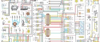
Relay and fuse layout diagram for Volkswagen Golf 3, Vento (1H)
The information applies to cars: Volkswagen Golf 3 / Volkswagen Golf 3 (1H1, 1H5) 1992 - 1998 Volkswagen Vento / Volkswagen Vento (1H2) 1992 - 1998
Layout of fuses and relays in the PDU Golf 3, Vento and their purpose.
Layout of fuses and relays in the PDU:
01 - 10A - Low beam of the left headlight 02 - 10A - Low beam of the right headlight 03 - 10A - License plate lamps 04 - 15A - Windshield wiper and washer of the rear window 05 - 15A - Wiper and washer of the windshield 06 - 20A - Heater heater 07 - 10A - Right side lights and tail light 08 - 10A - Left side lights and tail light 09 - 20A - Heated rear window 10 - 15A - Fog lights 11 - 10A - Left high beam 12 - 10A - Right high beam 13 - 10A — Bibikalka 14 — 10A — Reversing lights, heated washer nozzles 15 — 10A — Fuel cut-off valve, speedometer drive sensor 16 — 15A — Dashboard 17 — 10A — Direction indicators and emergency lights 18 — 20A — Fuel pump and heated lambda probe 19 - 20A - Radiator and air conditioning fan 20 - 10A - Brake lights 21 - 15A - Interior lighting, electronic clock, MFA, trunk light 22 - 10A - Radio, cigarette lighter
From myself: It seems to me that the fuse for the fastener is combined with the interior lighting and the MFA.
Number in the PDU - Number on the body - Purpose
01 - 13 - Air conditioning compressor relay 02 - 72 - rear wiper and washer relay 03 - 30, 32 - Injection and ignition system relay 04 - 18 - load relief relay, contact X of the ignition switch 05 - not used 06 - 21 and 22 - Relay breakers for turn signals and emergency lights, as well as trailer (No. 22) 07 - 33 - Headlight washer motor relay 08 - 19 and 99 - Relay for wipers and windshield washer 09 - 4 and 29 - Seat belt warning relay 10 - 15 - Jumper wire for PTF 11 - 53 - Sound signal relay (for a single-tone signal - jumper) 12 - 67, 80, 167 - Fuel pump or pre-heater relay (diesel) 13 - 53 - Pre-heating relay (22) or starter interlock relay 14 - 79 — ABS relay 15 — 79 — ABS hydraulic pump relay 16 — 79 — ABS relay 17 — ABS valve and pump fuses 18 — Electric seat and air conditioning fuses 19 — Not used 20 — Starter and reverse light relay 21 — Lambda heating coil relay probe 22 - Not used 23 - Not used 24 - Not used
Diagram and pinout of the rear side of the relay and fuse box
If you have not found information on your car, look at the cars built on the platform of your car. Most likely, the information on repair and maintenance will be suitable for your car.
Volkswagen golf 3 fuses and relays
1 Air conditioning relay 2 Rear window wiper/washer relay 3 Electronic engine control unit relay 4 Main ignition circuit relay 5 - 6 Turn signal switch relay 7 Headlight washer control unit 8 Windshield wiper/washer intermittent operation relay 9 Seat belt indicator relay safety 1995 10 Fog lamp relay 11 Horn relay 12Pro Volkswagen: Volkswagen Golf | Autopedia wiki Fuel pump relay 13 Intake manifold heater relay 14 - 15 ABS pump relay 16 Reversing light relay (Ecomatic) 17 High beam headlight relay (Ecomatic) 18 Low beam headlight relay (Ecomatic) 19 Fuse (30A - air conditioning, Climatronic 2, 0/2.8 (1993) 20 Start inhibit switch relay 21 Oxygen sensor relay 22 Seat belt indicator relay (1995) 23 Vacuum pump relay (Ecomatic) 24 Thermal fuse (20A) – Power windows F1 (10A) Left headlight - low light, electric motors for headlight range control F2 (10A) Low beam - right headlight F3 (10A) License plate lamps F4 (15A) Rear door glass cleaner and washer F5 (15A) Cleaners, washers, headlight washers F6 (20A) Heater fan F7 ( 10A) Front and rear lights - right F8 (10A) Front and rear lights - left F9 (20A) Rear window heater F10 (15A) Fog lights F11 (10A) High beam - left headlight F12 (10A) High beam - right headlight F13 (10A) Sound signals F14 (10A) Reversing lights, washer nozzle heaters, central locking, electric door mirror, seat heater, cruise control system, electric windows F15 (10A) Speedometer, intake manifold heater F16 (15A) Backlight instrument cluster, ABS indicator, SRS indicator, sunroof, Thermotronic heating system F17 (10A) Hazard warning lights, turn signals F18 (20A) Fuel pump, heated oxygen sensor F19 (30A) Radiator fan, air conditioning relay F20 (10A) Brake lights F21 (15A) Interior light dumps, trunk light, central locking, sunroof F22 (10A) Radio, cigarette lighter fuse
Fuses under the hood
On vehicles with diesel engines, the electrical power supply circuit for the glow plugs is protected by a high-power fuse in the form of a fuse link.
p, blockquote 13,0,0,0,0 —>
p, blockquote 14,0,0,0,0 —>
On some models, when the radiator cooling fan is turned on, a fuse link can also be used.
p, blockquote 15,0,0,0,0 —>
Video “Indicator fuse, demonstration of operation”
In this video you can clearly learn about the safety devices in the Volkswagen Jetta.
Almost the entire system of Volkswagen Jetta power circuits, on which the operation of the vehicle’s equipment depends, is protected by fusible contact elements, which are combined into a so-called fuse block. Through relays, which are also included in this block, such energy consumers are connected as:
- lighting lamps;
- electric cooling fan motors;
- fuel pump, etc.
This unit and its serviceability are of particular importance for the stable operation of the main systems of the Volkswagen Jetta model. That is why these contact elements are combined and placed in a special mounting block. According to the instructions, it is located in the interior of the Volkswagen Jetta, on the left side of the instrument panel. There is a top shelf, which in turn consists of:
- lower casing of the instrument panel;
- fixing screw;
- instrument panels;
- cover protecting the unit.
This is where the block is located, where in case of a malfunction you need to look. As a rule, a faulty or burnt-out contact element will give itself away. It will have a melted metal part with a black coating. It is also possible that the colored case will be distorted.