Alarm on a Priora is a serious issue; everyone is afraid for their car, trying to protect it to the maximum. The Priora is equipped with an alarm system from the factory - an immobilizer (immobilizer). On a Lada Priora car, it allows you to partially protect the car from theft. The immobilizer on the Prior is a factory anti-theft device combined with the car's electrical package, which is located under the center console. Owners immediately try to disable the immobilizer on their Priora, because they consider it archaic and prefer to install a more advanced alarm system on the car instead of the standard anti-theft one. Installing an alarm on a Priora will cost approximately 10,000 -17,000 rubles.
Disabling the immobilizer on a Priora is not easy. The engine is started by an electronic engine control system, which also blocks its operation when the immobilizer is turned on. And already in the electronic control unit of the car, in the place where the EEPROM circuits are stored, the process of data exchange with the immobilizer takes place, and at the ECU level there is a ban or permission to start the engine. You can turn off the alarm on a Priora yourself, but this requires knowledge of electronics and special tools.
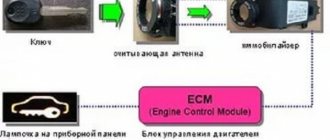
What is an immobilizer for?
The immobilizer will allow you to start the engine only if the key is recognized in the ignition switch. This blocking device, by transmitting a signal to the ECU, can block sparking and fuel supply. The immo receives a signal from a key fob with a chip that sends a key recognition signal.
That is, even if an attacker fakes the ignition key itself, but does not fake the key fob, he will not be able to steal the car. An impulse is sent from the key fob chip, and without the key fob, the key is a plug for the ignition switch. Its work with the data of the electronic control unit is carried out in seconds, and during this time the immobilizer manages to determine the authenticity of the chip.
Key fob and its functions
The control key fob is an ergonomic, 3-button chip key without an display panel. It does not have the ability to provide interactive support for the basic alarm control functions. The main task of the key fob is to reliably transmit a control signal without monitoring its execution. Functionally it looks like this:
- there are 3 control buttons on the key fob; right, front control button of key fob No. 1 – unlocking the Lada Priora car alarm;
- left, front control button of key fob No. 2 – unlocking the hood or trunk;
- central, rear control button of key fob No. 3 – activation of the car security function;
- all Lada doors are blocked;
- the car door locks will be activated without arming it;
- the car will be disarmed;
- Pressing the key fob button once opens the trunk;
Important: if, when you press the key fob buttons, the indicator LED does not light up or flashes twice, its CR2032 battery must be replaced.
Operating principle of the immobilizer
The principle of immo operation is that while the engine is turned off, the ignition system is blocked, and when the key is inserted into the lock, it begins its work. One of the main elements of the immobilizer device - the antenna - uses an adapter to recognize the signal from the chip inside the key fob. If there is no key fob with a chip, the immo antenna will not receive the signal and the system will not work. After recognizing the key installed in the ignition switch, a positive signal is sent from the ECU to unlock the ignition system. The anti-theft system is completed within seconds and the vehicle is ready to start.
Principle of operation
The principle of operation of the standard Priora alarm, like any other, with reliable dynamic coding, is quite simple and understandable. The activated signaling system accepts for execution exclusively the commands of the native, trained chip installed in the ignition key of the Lada Priora. This will be followed by a series of logically related actions:
- the communication coil, having received a reliable encoded signal from the ignition key chip, forwards it to the standard immobilizer (IMMO) of the Lada;
- he, in turn, checks the received reliable, encoded signal with the code recorded in his memory;
- if they match, the immobilizer sends a command to the authorized engine start of the Priora ECU;
- The Lada ECU, having received a signal from the IMMO alarm, unlocks its electrical circuits;
- If there is an unauthorized attempt to start the Priora engine, the IMMO will not send a confirmation signal to the ECU and the control circuits will not be unlocked. In addition, a siren warning signal with light flashes will sound;
- in addition, the car key fob, built into the chipped ignition key, controls the central locking of the Lada Priora and its window lifts;
- By installing shock or volume sensors yourself, the alarm system receives an additional option to increase its reliability.
Important: be sure to require activation of the standard Priora alarm system when purchasing it. Otherwise, you will have to configure it yourself using a training key with a red insert. In this case, various nuances with its performance are possible.
Causes of immobilizer malfunction
Sometimes the immobilizer of VAZ cars breaks down, and the driver cannot go anywhere in the car. Immo malfunction can occur for a number of reasons:
- Battery completely discharged;
- Technical difficulites;
- Software problems.
The worst way to kill an immo is to completely discharge the battery or simply disconnect the battery from the car's power supply. De-energizing the network will result in a chaotic code being written to the EEPROM circuit in the ECU, all settings will be lost, and the immobilizer will block engine operation.
Technical problems are problems with the boards, immobilizer antenna, or its adapter. The most common failure is a “burnt” board. You can accurately determine which part has failed using the anti-theft device diagnostics. It is important to monitor the immobilizer fuse in the Priora, because it serves as a consumable element in the overall chain. Exactly also a breakdown of electrical equipment can adversely affect the operation of the immobilizer. The problem may occur after replacing the engine or electronic control unit. When replacing the engine, it is worth installing a new ECU and a new immo chip.
Software problems are failures of the code recorded by a specialist. They can occur in EEPROM cells or the alarm key fob chip. If the operation of the ECU chip can be corrected using a computer, adapter and equipment, then the key fob chip will have to be changed. There have been cases of blocking due to interference from smartphones and other mobile devices.
Notes on implementation of schemes
Let us immediately note: if there are no window lifters, the second diagram will not contain parts K2/K3. Then you only need to cut one wire. Sometimes only the rear windows are missing. This means that relay K3 is excluded. And the diodes connected in parallel with the winding can be absolutely anything.
Now we list the requirements for an element called “relay”:
- Operation voltage – 12 Volts;
- Switching current – 10 A or higher;
- The current consumed by all relay windings should not exceed the value specified in the instructions for the signaling. Usually it is 200-300 mA.
It is the last requirement that is often violated.
In order for “scheme 2” to work, it is necessary not only to assemble it, but also to program the main unit: you need to enable the “2-step unlocking” option. And be that as it may, control impulses cannot be made too long. Use values of 0.7-1.1 seconds.
Power cables (cord X1-6) can only be connected using twists.
The cross-sectional area of the wire must be sufficient to withstand a current of “10 Amps” (this does not apply to signal circuits). A fuse protecting the power circuits must be installed. And of course, before installation, remove the negative terminal of the battery.
Signs of a faulty factory security system
- the car does not start;
- the electronic control unit does not respond in any way to pressing the key fob;
- the system does not work when hitting the surface of the body;
- constantly activated for no apparent reason;
- the doors are locked after pressing the open button.
Malfunctions are often associated with the design of the standard security system. Owners of domestic vehicles note that after several years of operation, the starter does not activate when trying to start the engine, or turns off after a few revolutions.
If one of the problems occurs, turn off the device, then contact the installers to diagnose and determine the cause of the problem. Before contacting the service center, test the system yourself, following the sequence of measures.
Tips for motorists
On a Lada Priora passenger car, the standard alarm system installed by the manufacturer of this car should be triggered when you press the corresponding button on the remote control key, sending a signal to the APS-6 unit, which will give the command to open or close the doors of your car. This happens only after the remote control is activated with a learning code key from the immobilizer.
The most common cause of failure of the standard alarm system of a Lada Priora car is the remote control (RC), located directly on the ignition key. The first signs of a malfunction are the activation and deactivation of the alarm not from the first press of the corresponding remote control button. Sometimes you have to press the button even 5-6 times to activate the system.
If, however, after repeatedly pressing the remote control button with more force than usual, the standard alarm goes off, then a possible malfunction in this case may be an increase in the distance from the button to the electronic board located inside the remote control. This happens due to a slight sagging of the electronic board. You can check this by disassembling the remote control and taking out the electronic board, and using something to press the buttons located directly on it. If the system works, this problem can be cured when assembling the remote control by placing a thin dielectric plate under the bottom of the electronic board, thereby bringing it closer to the external buttons of the remote control.
Another problem with a key with a remote control, which causes its operation to fail, is the appearance of a microcrack in the electronic printed circuit board, which leads to damage to the electrical circuit. This is due to the fact that the screw that fastens the remote control housing compresses the printed circuit board, and when you press the remote control buttons hard, the board bends slightly, which over time can lead to the appearance of microcracks and failure of operation. In this case, the printed circuit board will have to be replaced, and the price of this issue will be about 800 rubles.
Also, a possible malfunction may be the loss of contact between the radio module leg and the remote control circuit board track. And this happens due to weakening of the soldering, as a result of which a film appears inside this contact as a result of oxidation, preventing the passage of the electrical signal. This malfunction can be cured by carefully soldering this contact.
Algorithm of actions
- Make sure there are no signs of damage to the key fob. Check the functionality of buttons and contacts.
- Check the power supply. If necessary, replace with a new one.
- Check the functionality of the central control unit. If the central unit breaks down or malfunctions, you will need to contact the service center installers to install new software.
- The device that detects impacts on the surface of the car may not work if the settings are incorrect.
- Drivers often encounter the opposite problem - the system reacts to the slightest contact with the body as a result of falling leaves, wind, rain, snow, etc. You will also need help with setup here.
Another common problem that the driver cannot cope with on his own is the loss of connection between the power supply and the electromagnetic contact. The contact ensures uninterrupted opening and closing of the prior doors. To determine the problem, you need a special device - a multimeter. Depending on the reasons that caused the malfunction, reinstallation of the software or replacement of parts is required.
Replacing rocker arms on a VAZ 2107
Rockers (rocker arms) are one of the elements of the valve timing mechanism of the VAZ 2107 engine. The purpose of the part is to transmit energy from the camshaft cam to the valve stem. Since the rocker is constantly exposed to mechanical and thermal stress, it wears out over time.
Rocker arms are designed to transfer energy from the camshaft lobe to the valve stem
Determining the suitability of rocker arms
If during operation of the “Seven” there is a decrease in engine power or a characteristic knocking sound is heard in the cylinder head, then the likely cause is a broken rocker arm. During repair work, it is necessary to clean the rockers from dirt and carbon deposits and check them for wear and damage. If any defects in parts are found, they are replaced with new ones. If the rocker arms are in normal condition, install the products on the cylinder head.
If the rocker arm is heavily worn or there is visible damage, the part needs to be replaced
Is it possible to level the rocker arm?
When adjusting valves or repairing the cylinder head, you may notice that the rocker arms are slightly at odds with respect to the camshaft, i.e., the distance between the rocker plane and the camshaft journal is not the same. To eliminate this nuance, some owners of “classics” align or change the springs that press the rocker arms, or replace the rocker itself, but the problem may still remain. In fact, on all classic Zhiguli models, including the VAZ 2107, misalignment is not as bad as incorrect valve clearance. Therefore, it is the gap that deserves attention. The main thing is that the parameter is adjusted properly and is 0.15 mm when cold.
When the rocker arm is skewed, some motorists change the part itself, the springs, and sometimes the camshaft, but they do not achieve the desired effect
How to replace a rocker arm
If there is a need to replace the rocker arms on the “seven”, for example, 1 part in case of its breakdown, then it is not necessary to dismantle the camshaft. To do this, it will be enough to pry the spring with a screwdriver, remove it, and then remove the rocker itself. The new part is installed in the reverse order. If all the rocker arms are being replaced, then it is wiser to dismantle the camshaft.
How to activate the immobilizer
- To activate the immobilizer on a Priora, you will need a training key. It is almost 2 times smaller in size than the real one, and is used only during “training”. To work with it, you should adhere to the following algorithm of actions:
- Close all door locks;
- Insert the training key, turn it and hold it in the final position for at least 5-6 seconds, and then turn it back. During these 5-6 seconds, the indicator light on the dashboard should blink continuously. If it goes out ahead of time, it means something was done wrong.
- Remove the training key from the ignition switch and insert the working key, start the ignition system. All this needs to be done while the light on the dashboard is flashing. If everything was done correctly, three beeps will sound first, followed by two more after a pause. If this does not happen, then the immobilizer is faulty.
If the light on the dashboard is still blinking, turn the key back.
Immo can “remember” several keys, but the learning process must be continuous. The working key with which this operation was carried out will be registered in the prior immobilizer.
Training procedure:
Carrying out the training procedure leads to the following consequences:
- the engine control controller activates the anti-theft function if it has not been activated;
- the system changes its password to a new one chosen at random;
- a new system password is written into the training key;
- all remote controls that were previously trained are erased from memory;
- The codes of those remote control units that were trained in this training procedure are stored in memory.
The training procedure is applied in the following cases:
- activating the anti-theft function in the controller (for example, in a new car or replacing a faulty controller);
- erasing old and training new remote controls if lost;
- changing the system password if the owner admits that his system password may have been read (for example, when selling a car from one owner to another)
- remote control training when replacing a faulty immobilizer with a new one.
Only new remote control units or those that were previously trained using the training key used in this training procedure can be trained. It is impossible to learn a remote control key from another car into your car.
Please note: Due to the importance of the training key, it is not recommended to use it for everyday use and should be kept in a safe place.
Before starting the training procedure, fill the car with at least 10 liters of gasoline so as not to get confused by the squeaks.
How to disable the immobilizer
It is difficult to disable immo on your own, because it is activated at the car dealership upon purchase, or at a car service center only if the owner of the car expresses his desire. Disabling the immobilizer on a Priora means reprogramming the electronic immo control unit. But not everything is so simple - an adapter and software are needed to change the code, because the immobilizer operating algorithm is written in a programming language that is not basic for computer operating systems. Remember that you can disable the immobilizer only when you are sure that the car is safe.
The procedure for disabling the immobilizer may vary. It all depends on the generation of the device board - either M73 or M74 was installed in the immobilizer. Anyone who is looking for how to independently disable the immobilizer on a Priora should find a K-Line class adapter.
Hydraulic compensators for a classic engine - installation, pros and cons...
I don’t even know where to start, but I’ll try, it means I’ve been confused with them for a very long time, I read the forums, followed the answers, I found a dealer already in our HERMES region, I wrote it off, he wrote that there are only spare parts for the Hermes GKK and the camshaft VAZ 21214, as far as the camshaft is concerned, all forums advise setting it to 21214, although there is a person on an Autolada who drives a GKK and his relatives for a penny, i.e. a classic camshaft and everything works great, although in all the articles and letters from everyone from the VAZ it is written that it is necessary to use the camshaft from the VAZ 21214, they say that it has a different cam run-off, in addition, it has a greater degree of opening of the intake valves than the exhaust valves, but this is more refers to the engine itself rather than to the GKK.
After much thought, I decided to take the GKK from the VAZ 21214, however, on the Nivovodov forum I realized that there are two types of them with a thin body of the plunger and a thick one, on the Nivovod forums I came across a message that the GKK with a thin body was supposedly fake, although there was a GKK on the body of the GKK itself the mark was engraved with a laser and they were made of very high quality, I bought 4 with a thick body and 4 thin ones, because I couldn’t find 8 pieces with a thick one at that time, although I repeat once again the nivovods wrote that this was a fake, later it turned out that they were simply made produce another plant, nowadays you can’t find a thick-bodied GKK...
After I bought 8 GKK, a camshaft 21214 and a ramp for the GKK, I began to try to understand how I would install them, I found an article on the Internet by Vyacheslav Igorevich Vereshchagin, he lives in St. Petersburg, E-mail: , website: https://ver -sla.pochta.ru/ I quote its text, the punctuation and grammar of the author are preserved:
Hydraulic compensators (pros, cons, installation on a VAZ2101-07) Epilogue For six years now I have been the happy or unfortunate owner of a people's car. The desire to “charge” the car disappeared quite quickly; the only thing that was done in this direction was the installation of a Solex 2183 carburetor on an intake manifold that was polished and adjusted to the head. For all the time I have been using this vehicle, I have never been able to get used to the fact that the engine operates extremely loudly and at the same time throughout the entire audible frequency spectrum, which undoubtedly prevents me from listening to music at speeds of up to 100 km/h; further listening is also unpleasant, because .To. The aerodynamics of the body are still the same. It’s hardly possible to fix the body, and even if it’s possible, it’s costly, both in time and money, so I’ve long been toying with the idea of at least calming down the engine, and now the moment has come! Domestic manufacturers and designers have adopted hydromounts for the classics, Chevy-Niva forced them, and third-party developments from such manufacturers as LLC Foreign Economic Association "Hermes" https://www.gidrokompensator.ru/ and others have appeared. Taking the little pot of money, I went to the market, the one on Fuchik Street in St. Petersburg, because... Calling stores did not give a positive result, where I was offered a choice of two types of hydraulic supports, from Chevy-Niva 21214 and the above-mentioned ones from Hermes. Having gutted the Hermes packaging, I read the installation instructions, from where I learned that I didn’t want to bother with inserting washers and drilling holes in the camshaft pastel, plus this kit was the last on the market and where to look for spare parts in case of a long trip and breakdown, I don’t know. As it turned out later, there is nothing bad in the washers - only good things come from them; after a long stay, the hydraulic support quickly returns to normal working condition because The pump has to pour less oil into it. Outwardly, I was confused by the presence of plastic in the design of the oil supply frame. In short, I bought 8 hydraulic mounts from Niva, a Niva oil frame and a Niva camshaft in pastel. The purchase of the latter was justified by the statement of some comrades about the increase in power due to longer valve timing and higher valve lift, plus the Nivov pastel was milled for supplying oil to the oil frame and it seems that the shaft itself is more suitable for hydraulic mounts (all this was read on forums on the Internet) . The valve lift actually turned out to be 0.8 mm greater than my old one, which adds about 1 square meter around the perimeter of the valve. cm additional section. I didn’t compare the shape of the cams in detail, they seem to be dumber and that’s it. Later, I bought an additional long pin for fastening the camshaft pastel and screwed it in place of the old one, which now had to, in addition to the pastel, also press the oil pipe. When visiting the market, I forgot to consult the Chevy Niva literature about the procedure for installing hydraulic supports, probably in vain, because... In the city stores I found only one book on this machine, in which nothing was written about hydraulic supports. I decided to break through with a fight...) and the fight turned out to be long, for an operation that for some people takes 3 hours, I spent two days 9. Repeatedly, of course, I will do it in 3 hours, but the first time - as always, we just don’t forget. The point of writing this article is to prevent others from making mistakes. Next, I’ll tell you how to correctly install hydraulic compensators from a Chevy Niva on a classic. Installation First of all, I want to say that this instruction is my personal experience and should not be taken as a manual recommended by the manufacturer, you can repeat everything described, but at your own peril and risk, in short, responsibility for damaged components and God forbid I don't carry engines. Cross-section of hydraulic support 21214 Chevy Niva (the principle of operation is the same for all, so the instructions can also be used when installing other supports on other cars)
1 - body 2 - ball valve assembly 3 - return spring 4 - stop rolling 5 - bypass holes (lower for oil, upper for air) 6 - upper part of the plunger 7 - lower part of the plunger 8 - oil A - pre-valve area B - area hydraulic cushions The principle of operation is as follows: oil through a hole in the GO (hydraulic cushion) housing (not shown in the figure) enters cavity A, after which it flows through ball valve 2 into area B until the plunger 6.7 rests against the rocker, which in turn, into the camshaft cam, which ensures constant pressure and the absence of timing gap and, as a result, noise reduction in contrast to the old kinematics with thermal clearances. Check valve 2 prevents the oil from leaving area B, but circulation still exists, the oil slowly seeps through the gaps between 7 and 1. That is why, after long periods of parking, the engine starts with a knock more characteristic of a diesel engine. Those. in any of the camshaft positions, a certain pair of valves is recessed and the valve springs through the rocker, resting on the camshaft cam, press on the camshaft, thereby emptying area B. The gap becomes very large and until the oil pump fills cavity B again, it can take up to 2 minutes (depending on duration of parking and ambient temperature, as well as the type of oil used) Therefore, warming up the engine after installing the HO (at least until the knocking disappears) becomes a mandatory component of the life of your car. Now that we’ve sorted out the principle, let’s proceed to the installation procedure! For this we need: 1. set of hydraulic supports 21214 8 pcs. $110 2. set of new rockers (not necessary, but desirable) 8 pcs. $19 3. camshaft and pastel assembly i.e. selected without play 21214 (not necessary, but desirable, if you leave the old ones, you will have to solve the problem of oil supply, most likely by milling or slotting and filing the top of the boss on the central pin to a height of 8 - 10 mm) $43 4. oil supply frame 21214 1 pc. $24 5. long camshaft pastel pin $ 6. copper washers internal diameter 9 mm thickness about 0.2 mm (not necessary, but desirable for sealing the oil supply tube) 2 pcs. $ do it yourself 7. a set of valve stem seals (not necessary, but it is advisable, since it’s in your head, it’s better to change it) $5-6 8. about 20 ml of motor oil, which you pour into the engine 9. medical syringe for 1-5 cc 10. plastic rod, sharpened into a cone on one side, 7-10 cm long and 3-5 mm in diameter 11. piece of wood Total $201 at the rate of $1=29RUR Remove the air filter along with the casing, the valve cover, the camshaft pastel with the camshaft itself , the sprocket can be left in the chain, but then still check the coincidence of TDC on the crankshaft and camshaft (the mark is not always opposite the ebb of the pastel, so remember whether it is on the right or left). We number the plates to which the rocker spring holders are hooked. We unscrew the standard supports, for this it is better to use a 21 socket ground off the end so that the grip of the nut splines is maximum, but I managed with a regular socket. I had an unscrewing torque of 150 Nm no less, so I put an extension pipe on the knob. Carefully!!! Do not knock out the windshield when the nut is removed. We dry out the valves, change the oil seals, and dry out the valves. We replace the central pin of the camshaft pastel with a long one. Next comes the most interesting part, stock up on clean rags or just rags. GO must be prepared for installation! They are delivered from the store filled to capacity with oil so that they do not corrode during storage. There is also a suspicion that on the Chevy Niva there are grooves in the pistons for the valves, so an unpreserved GO can be installed without disassembling it; on a classic, there are no grooves in the pistons, so when installing an unpreserved GO, the valves meet the pistons. Look at the picture above in the text! Disassembly should be done one by one because The insides cannot be confused; they are fitted with a maximum allowable gap of 24 microns. Using a wide slotted screwdriver, remove stopper 4, pull out plunger 6, then, carefully prying the inside of plunger 7 with a screwdriver, or turning the body over and gently tapping it on a piece of wood, remove plunger 7; spring 3 will fall out on its own, don’t lose it. We wipe everything dry from the oil, without leaving fibers of the rag on the surface. We pay attention to plungers 6.7, fill the syringe with 0.8-1 ml of oil and squeeze it into the GO body, insert spring 3 back, insert plunger 7, it will not sink completely until you bleed out the remaining air. To do this, lightly press the valve ball with a plastic rod (do not try to press with an awl or a screwdriver; if you damage the ball, you will ruin the valve). Insert plunger 6 and try to squeeze the assembled GO, resting the sphere of plunger 6 against a piece of wood, if the gap C (see figure) is within 1.5-3 mm - everything is assembled correctly, if less - not enough oil has been poured, if more - bleed it off, slowly , but pressing hard on valve ball 2 and quickly releasing it. At the same time, the GO grunts. In my opinion, it is not advisable to put back the locking rolls 4, there is an extra rattle in the engine, the GO will not fall apart anyway, you just have to screw it in carefully without dropping it in the PYSOC. Having completed this operation with all GOs, you can begin installation. We install the oil supply frame and tighten the GO (they must be screwed in all the way by hand, otherwise the threads in the cylinder head need to be tapped), first tightening torque is 70-80 Nm to rub in the oil line, then release and tighten with a torque of 20-23 Nm, with a stronger tightening the body The GO bends and begins to jam (that’s what happened to me). It is advisable to tighten it to the maximum torque, allowing the GO to be pressed freely, provided that it is completely returned to its original position by the return spring. We install the rocker, put the camshaft in place in the bed so that the camshaft pin coincides with the large hole in the gear, screw it in, not forgetting about the oil line and two copper spacer washers (tightening torque for the bed nuts is 25 Nm, tightening order is an unwinding spiral clockwise, starting from the oil line nut, tighten in two steps), tighten the gear (tightening torque 45 Nm). We turn the engine so that the camshaft makes a full revolution (the easiest way is to jack up the rear wheel, put it in 4th or 5th gear and turn it by the wheel). If everything turns without jamming or extraneous sounds, good, check the marks on the crankshaft and camshaft for TDC. If everything is in order, you can attach the valve cover and try to start it. If it sticks, you messed up somewhere, read the instructions first. It’s better to also buy a Chevy-Nivovskaya valve cover, it’s double-layered and muffles the sound much better. The engine may knock, but no more than 2 minutes, after which it’s pure pleasure. Collect everything you haven't collected yet. Pros — Reduced timing noise to almost zero! — Increasing the timing belt service life by a factor of two for sure! — Stable operation at idle even at 600 rpm (it happened to me)! — The resonance of the engine and gearbox of enormous amplitude with a frequency of 1-2 Hertz has disappeared when starting off!!! A disease that I thought was congenital (I changed the engine and gearbox mounts, as well as the clutch assembly) - Smooth acceleration, without failures, like a trolleybus - The efficiency should increase, i.e. fuel consumption will decrease - The ignition timing mark used to dance around 5 degrees, now it seems to have frozen in place. Cons - Complicated design - loss of reliability, but foreign cars drive 400 thousand km, and the owners don’t remember about GO - It feels like the maximum torque has crept from 3200 rpm to 4000 rpm, the car accelerates along two acceleration straight lines - flat up to 3200 and steeper from 4000 to 5500. Some may find it uncomfortable when driving in the city, but you get used to it quickly. Perhaps this effect was produced by camshaft 21214. - $200 is not expensive on the road. Budget option - a conversion from Hermes costs $110, you can fit in if you do it yourself, but where to look for spare parts if something happens...) Prologue I’m as happy as an elephant, and it seems like there are already a lot of people like me, love your “swallow”, join the club “ classics" with hydraulic supports. Many people think about the softness of the hydraulic compensator and the blurred opening phases because of this. Send them to the GARDEN! According to the manufacturer's instructions, the hydraulic support must be replaced if its subsidence is more than 0.1 mm, and the thermal gap on a hot engine without hydraulic support is 0.2 mm, in my opinion, everything is clear. GO = hydraulic support = hydraulic compensator Installing a single-row chain and valve cover from a Chevy Niva does not give even a third of the result in reducing noise (I installed it for a friend) compared to installing a GO, but now the double-row chain is clearly audible, we will change Grammar, punctuation, syntax and spelling errors there are, I can’t help but have them, sorry.
Changed and added 12/06/06 It began to get colder outside and the knocking of valves when the engine warmed up began to last much longer, this was the reason to once again go to pieces. Visible wear was discovered on the rockers in the middle, I began to think and measure everything that could be measured, and this is what it turned out to be! The cups into which the hydraulic supports are screwed are milled in an incredibly ugly way, the difference in height exceeds a millimeter from cup to cup! In such a situation, it is simply impossible to hermetically press the oil-conducting frame to them, with a tightening torque of the hydraulic support of 20-23 Nm! Those. The hydraulic mounts experienced oil starvation, which was bad. The disassembled GO shows wear on the working surfaces, although apparently acceptable. The way out of the situation is simple: by placing a ruler on the cups of the block head, I found out the difference in their heights, then I made a mandrel from the tube, which I cut from sheet copper (0.3 mm thick) spacer washers (annealed copper, i.e. heated to red) and brought together, placing them under the oil-conducting frame with a height difference of up to 0.1-0.2 mm. I reassembled and warmed up the engine, there is no more valve knocking at all. When the hydraulic support was disassembled, I blew into the plunger with my mouth, and so I found out that for oil to flow into the hydraulic mount, a pressure of less than 0.1 atm is required. When the engine is running on the pressure gauge at 2000 rpm, as much as 2 atm, i.e. Oil leakage from the hydraulic mount when parked, provided the oil supply system is sealed, is compensated almost instantly. Hence the conclusion: If there is no doubt about the quality of the oil or they are new, and a knocking sound is observed when starting the engine, look for where the oil is leaking.
I did almost everything the same way, besides, I had a few questions, I wrote to him, he answered me, for which I am still grateful to him, they helped a lot, in addition, I read the article from the nivovods https://www.niva- faq.msk.ru/tehnika/dvig … rov_gk.htm which talked about the bulkhead of the gas condenser, I realized that the main condensate valves are sensitive to: debris in the oil, to jamming, this can be caused by their constriction and oil starvation, based on this I decided to installation to disassemble them, this article from Nivovodo tells how. so I removed all the old rocker, springs, my camshaft, bought a Polish torque wrench, and began the installation, I decided to install one GKK at a time, so as not to confuse the plunger pairs, this is very important, otherwise they will not work at all. I took one GKK, disassembled it, washed it in white spirit, completely pumped out the oil from under the adjusting bolt with a syringe, because otherwise the GKK body simply wouldn’t screw in because the oil wouldn’t allow it to screw in, took the plunger body and screwed it in where the adjusting bolt used to be, tightened it to the values indicated in article, (of course it is first necessary to install an oil ramp) I simply will not list them, since on some they may be much smaller; first, as written in the article, I chopped copper plates and pre-annealed them. just like in the article, I stretched them out first and then tightened them as needed at the right moment, but!!! Here it is very important to ensure that the body of the plunger does not jam, i.e. we tighten the GKK body, lower the plunger into it, and try to press it; it should move easily in the GKK body and not jam, if we tightened it with the right torque and it jams, we loosen the GKK body and try to tighten it with such a torque that the plunger doesn’t jam, even if the torque tighten less than recommended, otherwise they will constantly jam, we don’t need this, after making sure that the plunger does not jam, fill it with oil, insert the plunger and pusher, put on the rocker, we do this with all the hydraulic valves (you need to do this very carefully), there is a lot of oil you don’t need to pour it, it can be completely at the bottom, you don’t have to pour it at all, at the factory they will be filled with oil, if you overfill the oil, then the car may not start at all until the valves are pressed together and seated until the valves close normally, I poured Don’t bother with the oil, naturally I had problems starting the car because the valves didn’t close, but after a while they all sank and the car started, so I would most likely not recommend filling it with oil at all, or pouring very little... so
We screw the camshaft, under the middle stud from the ramp, a tube for feeding the main gearbox, a gear and a chain, and collect everything else...
Of course, I told everything chaotically, but it was a long time ago, if you have specific questions, ask in this thread on the forum, I will answer with pleasure.
For M-74, the process of turning off the immobilizer will look like this:
Disconnect the battery, disconnect the immobilizer control unit from the network. A harness with cables and a double switch is connected to the immobilizer. The circuit is connected to the battery and computer using a VAG-COM adapter. The first button of the switch is activated, it “gives the go-ahead” to change the code. The code is changed in the WinFlash program. First of all, in the settings you select the module type and the information transfer speed parameter. The second switch button is activated; it is responsible for communication between the computer and the immo control unit. The standard lock code is retained, and the Eeprom cell data is overwritten. The whole process takes a long time, but you need to wait for contact. Upon completion of the recording process, the control unit is connected back to the vehicle network, and the battery is started.
Why are there no friends
Even the most shy and unsociable introvert needs a friend. At least in one. A best friend is a person who knows you well, is always ready to help, and is fun and cool to spend time with.
The older a person gets, the fewer real friends he has. After all, often the strongest friendships we have are with those whom we met in childhood, grew up and matured together. And then different situations happen in life when we find ourselves alone without our usual social circle:
- moving to another city or country;
- loss of contact with old friends due to the fact that you have families and do not have enough time to communicate;
- you just want to change your current environment because you have outgrown the level of your friends;
- your “other half” categorically does not like your friends or girlfriends.
This is not an exhaustive list, but whatever the reason for your loneliness, you can always meet new people who can become friends.
For M-73 the process will look simpler:
Installing the OpenBox program and the HxD file editor on your computer. Connecting the immobilizer to the computer via an adapter, the standard EEPROM code is read. The code is saved. Open the saved code in a file editor and add the first line with the text: FFFFFFFFFF. Save changes. But such a file can be searched on the Internet. Load the edited code into the immo memory through the program. Disconnect the module and install it in the car. Disabling the immobilizer using a crawler
It is easier to disable the immobilizer on a Priora yourself using a device - an immobilizer crawler for a Priora (most often they are produced by Starline). To do this you need:
Find and disassemble the immobilizer unit in the Priora. Before disconnecting from the network, connect to the computer via an adapter. Resolder the resistor chip to modify the blocker control module. Run Eeprom and Flash diagnostics, save existing versions. Install the “untrained” program in place of the old one. Solder the resistor chip. Deactivate the anti-theft system. To do this, you can change the ignition switch in the Priora to “update” the immobilizer. It’s just that the immobilizer training key will not be used in the future. Disabling the immobilizer without using a crawler
These methods have already been described and they are more reliable because they completely change the firmware of the device and provide a guarantee that the immobilizer will no longer break and will not leave the car owner in the cold. Using a waste module may be an innovative way, but it only masks the problem, not eradicates it.
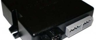
The standard alarm system on the Lada Priora consists of the following links:
- Control unit – connected to the glass unit control system;
- Communication coil – installed in the ignition switch;
- Main and demonstrative keys, which are equipped with a buzzer and contact keys;
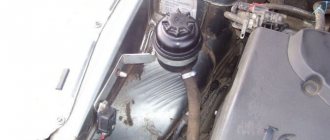
- Central key on the dashboard;
- The control unit is located on the right side of the brake pedal. It has several connection points.
Reliability level
Undoubtedly, the standard alarm system installed and configured on the Lada Priora is simple, reliable and fully adapted to difficult local weather conditions. Properly activated, it leaves no doubt about its functionality. Besides:
- the quality of installation and configuration of factory alarms is guaranteed by experienced factory specialists and the control service of the enterprise;
- The key fob is integrated into the regular ignition key. There is no need to wear them separately in a whole bunch;
- there is no need to equip standardly installed equipment with anything;
- The factory alarm system of the Lada Priora is covered by the factory warranty;
- if the Lada owner wishes to install and configure an additional sensor, there is a spare port;
Unfortunately, if the factory, standard installation is a big plus of such an alarm, then at the same time it is also a significant minus. Thousands of analogues of such alarms drive Lada Prioras across the vast expanses of the country. No mystery for attackers. But they are not looking for cars with alarms, but without them at all. You also need to understand these immobilizers, and time is money. And unnecessary problems are not for the criminal business.
Connection points for standard alarm systems on Lada Priora
- Hood end (-) – white, black in the connector in the middle;
- Ignition (+) – orange in the connector in the middle;
- Button for opening the trunk lid (-) – black, white in a small connector;
- Luggage compartment end switch (-) – black, white in a small connector;
- Factory sound warning system - black, white on the safety panel. Owners of VAZ models change or improve the existing protection. Upgrading protection on a Priora is not difficult. To control the central locking, you need to cut the brown wire in the driver's door and connect according to the diagram.
Connecting limit switches
The alarm is connected to the Priora central locking system through limit switches using diode isolation. You can download connection diagrams on social networks.
Basic limit switches
- Ignition – blue, black, located in the ignition switch area;
- Starter – red;
- Turns – blue and blue with black line;
- Ignition – orange;
- The hood tip is white with a black stripe;
- The generator is black with a brown line.
Installation map for Starline A93 Can+Lin car alarm for Lada Priora Lux 2014-15 manual transmission
1. To access the ignition switch connector, remove the lower part of the steering shaft housing. To do this, you need to remove the plastic trim under the steering column, releasing the clamps, then remove the lower part of the casing (fastened with three self-tapping screws and two screws).
Steering shaft housing. General form
Plastic lining fasteners
Plastic cover removed
Self-tapping screws and screws for securing the steering shaft housing
The lower part of the steering shaft housing has been removed
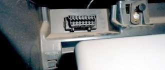
2. To access the VSM unit, remove the left side trim of the central tunnel (fastened with one screw). Then remove the VSM unit (mounted with a bolt and nut).
Self-tapping screw for fastening the side trim
Side trim removed
Bolt and nut for fastening the VSM unit
VSM block removed
3. Install the antenna module with built-in shock and tilt sensor on the windshield, LED on the left pillar. Install the service button covertly in any convenient place.
Possible location for installing the antenna module
LED installation location
4. Install the siren under the hood (attach it to the nut) and the engine temperature sensor (using plastic ties). Route the wires into the passenger compartment through the standard seal on the left side of the engine shield.
Possible siren installation location
Siren installed
Engine temperature sensor installation location
The temperature sensor is fixed to the pipe using ties
Standard seal. View from the salon
5. Secure the StarLine A93 central car alarm unit to the right above the BCM unit.
An example of the location of the central car alarm unit
6. Connect the StarLine alarm ground at the bottom left under the VCM unit under the standard nut.
Ground connection7. Connect the CAN bus and LIN bus StarLine in the harness of connector 3 of the BCM unit.
Conventional numbering of connectors on the VSM unit
CAN bus (yellow-red, pin 16 and gray, pin 15)
LIN bus (blue-white, pin
LIN bus connection
8. Connect the trunk limit switch in the harness of connector 3 of the BCM unit.
Trunk switch (yellow, pin 14)
Connect the hood end switch in the harness of connector 2 of the BCM unit.
Hood switch (white-black, pin 15)
Connecting the hood and trunk limit switch
9. In the harness of connector 2 on the BCM block, connect an alternative control of light signals (black and white wire of connector X3 of the Starline alarm system).
Light signal control (red, pin 5)
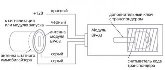
10. To bypass the standard immobilizer, remove the battery from the key and place the key in the StarLine BP-03 immobilizer bypass module. Then connect the bypass module to any wire of the standard antenna on the ignition switch.
Standard antenna wires (green and white)
11. In the ignition switch connector harness, connect the engine starting power circuits, power supply to the security system and the autostart power module.
Ignition (blue-black)
Starter (red)
Power + 12V (brown)
12. Program the security and service functions of Starline A93 (see installation instructions, section “Main menu for programming car alarm functions”, Table 1).
13. Program the vehicle starting parameters (see installation instructions, section “Main menu for programming car alarm functions”, table 2).
14. Adjust the sensitivity of the shock and tilt sensor (see the installation instructions, section “Connecting the transceiver (antenna module) and setting the shock and tilt sensor”). Factory sensitivity values: warning level of the shock sensor - 10, alarm level of the shock sensor - 5, tilt and movement sensor - 5. After setting, check the operation of the sensors, if necessary, repeat the setting procedure.
15. Check the operation of the Starline A93 car alarm. Reassemble the interior in the reverse order.
A simple scheme for connecting an alarm system to a Priora
A key module is installed in the driver's door. To find it, remove the trim. Take brown wires. He is responsible for sending the signal. Connect the signaling relay to its open. Connect the two wires that are connected to each end of the cut wire to the main unit. Relay connections are made to one end.
Complicated version
Find the 2170 bead block, identify the tri-core connector. Find the wiring: red-black, green-black, eleventh. Break all three contacts. Lead the wiring from the break point to the control unit. The difficulty is to get to the block. It is located in the gas pedal area. The front panel is removed to provide access.
Two schemes (simple and complex)
First of all, before connecting the alarm, you need to study the instructions included with it. The main unit always has relays installed: one of them closes when the locks are locked, the second acts on opening. The connector to which the relay contacts are connected usually has 6 pins. There is nothing complicated here.
In the first case, we will use only this connector. The second circuit uses another contact, called “signal output for 2-step lock opening”. Find it on the main unit.
We connect the alarm in a simple way
A push-button module is installed in the driver's door of the Lada Priora. The door trim must be removed and the connector for this module must be found:
We will need a brown cord from the connector. It is a signal, and the alarm relay is connected to its break:
Two wires connected to each side of the cut cord will have to be pulled to the main unit. The common contacts of the relay are connected to one of the wires.
All wiring in the considered circuit is signal, but this does not mean that the connection points need not be isolated. Wires should not touch metal parts of the car. If contact occurs, it is necessary to use additional protection: electrical tape, heat-resistant tube, etc.
The best option for connecting to the central locking system
Having made the connection, as discussed above, you can notice the following: all locks are activated from the key fob for closing, and only one, the driver’s, is activated for unlocking. This defect can be eliminated 100%, which will require 2 or 3 additional relays. First, let's look at where the connection points are:
The block that is visible in the photo is designated BUS-2170. It is equipped with three connectors, but we need one (three-row).
Find three wires in connector X1:
- Sixth (red-black). The cord goes to the actuators and is the power one.
- Thirteenth (green-black). Front right power window control cable.
- Eleventh. Same as “13”, but for the rear window lifter.
How to connect an alarm system to the central locking of a Priora Lux? Three wires are broken (all indicated), and the cables from the break points are pulled to the signaling unit. If you don't have rear power windows, the last cord will be missing. And if there are no power windows at all, cables 3 and 2 do not break (they are still missing).
The BUS unit will be installed behind the dashboard, near the gas pedal. To remove it, dismantle the side panels and unscrew two 10mm nuts. These nuts secure the block on both sides. From each of the break points, a cable is laid to the signaling system, which also applies to the brown cord coming from the door block:
Here we use additional relays (K1-K3), a 15 Ampere fuse and nothing more.
Central locking circuits
Locking and unlocking of the interior doors is organized through a two-step central locking chain. Three contacts of the electrical package control unit are connected to this circuit through a relay system. One power contact (12 V) and two contacts from which the control signal for the power window drives (front and rear) is removed. The two-step central locking circuit is connected through relay coils to the alarm module, and the door lock signals are removed from the alarm module.
Completion of educational program about Lada Priora
After reading, many will probably be overcome by a feeling of powerlessness. Indeed, all the described actions cannot be completed if you do not have experience in repairing Russian Zhiguli cars, as well as the skills of a specialist in electronic systems. The bulk of car owners are still ordinary people who use the vehicle simply as a household appliance and nothing more.
All thoughts are more likely to suit creative people - those who not only drive a Zhiguli, but always strive to improve. For this category of readers, all that remains is to add: all the necessary diagrams of connectors, connections, wiring are available in sufficient quantities on the network. So, you can pick up the tool and start installing the latest model of alarm system on the Priora, if one has not yet been installed to this day.